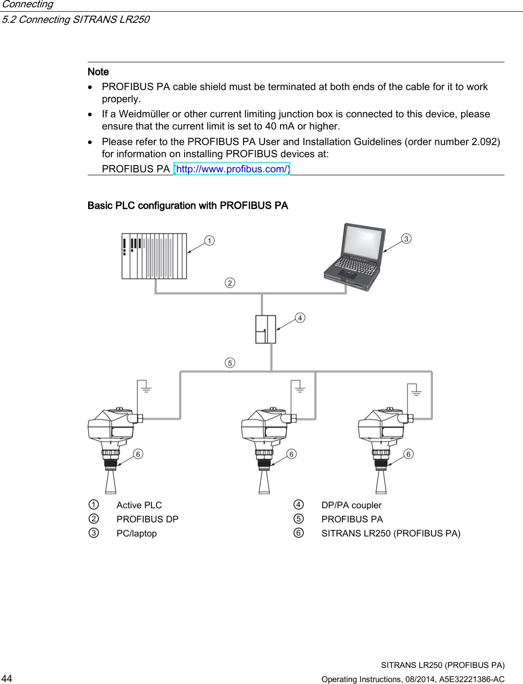
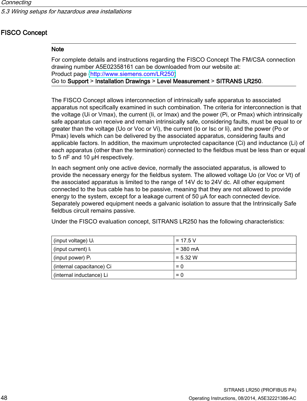
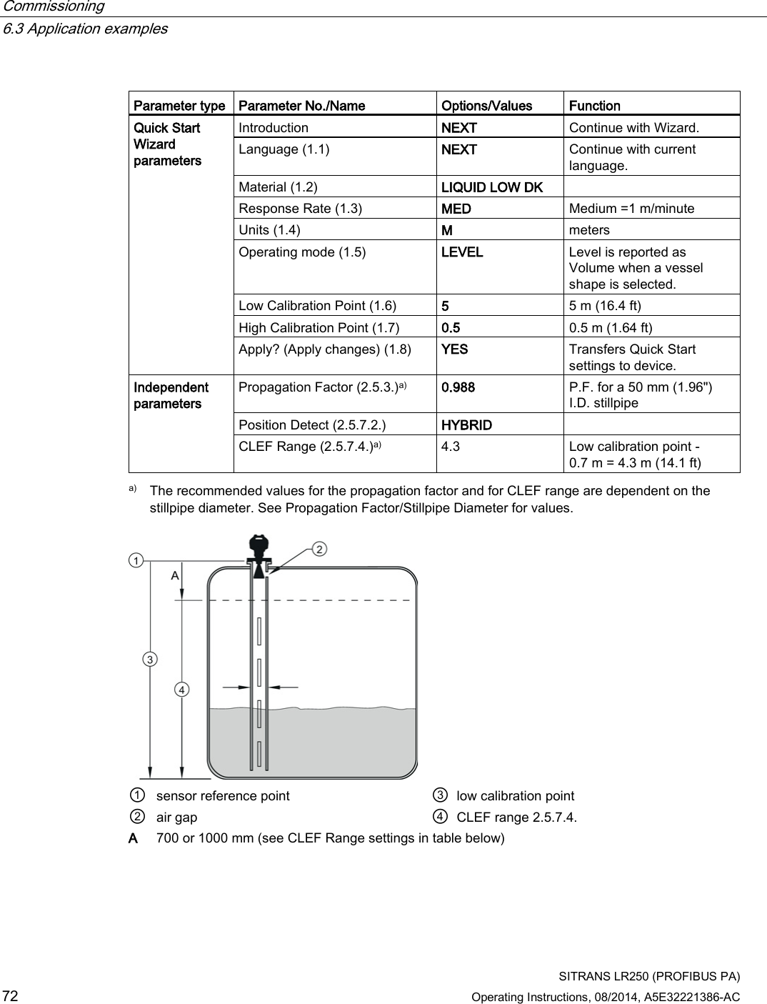
Siemens Canada Siemens Milltronics Process Instruments LR250 SITRANS LR 250 TANK LEVEL PROBING RADAR User Manual SITRANS LR250 PROFIBUS PA
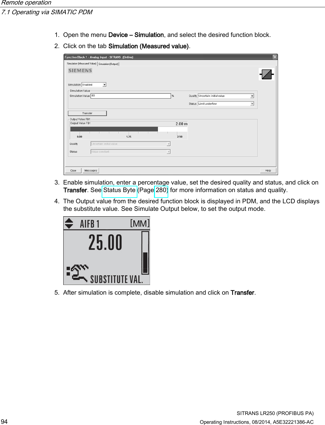
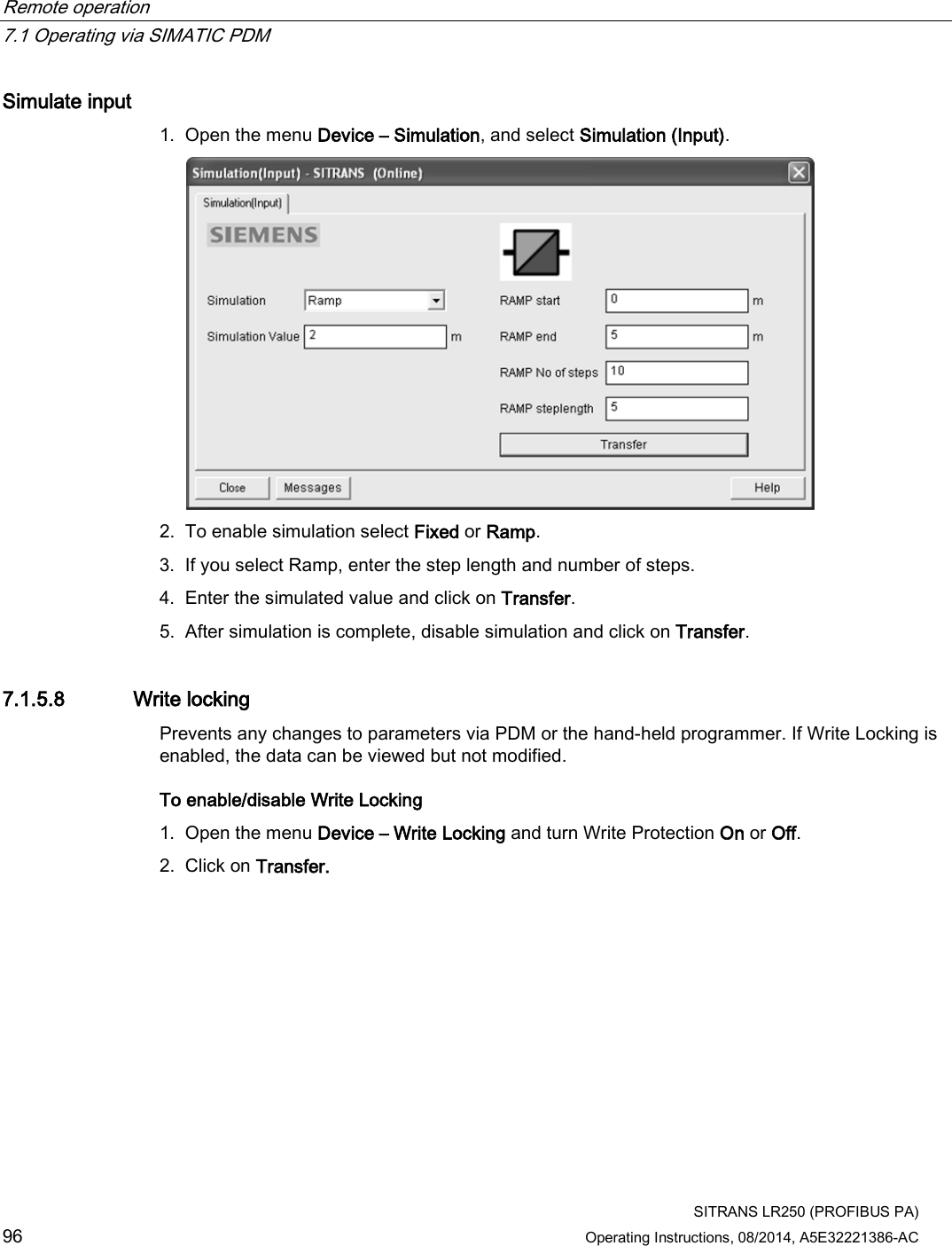
Siemens Canada Ltd. - Siemens Milltronics Process Instruments SITRANS LR 250 TANK LEVEL PROBING RADAR SITRANS LR250 PROFIBUS PA
Contents
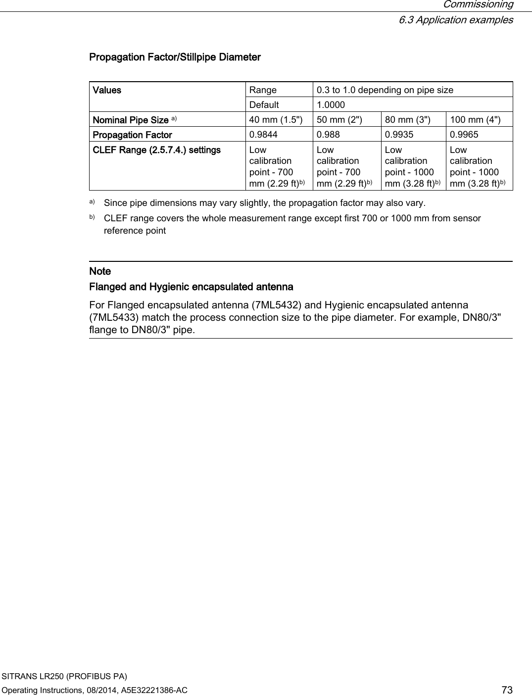
User Manual 5


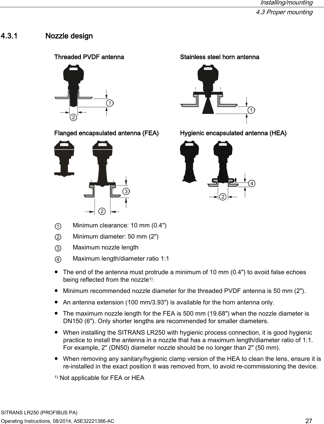
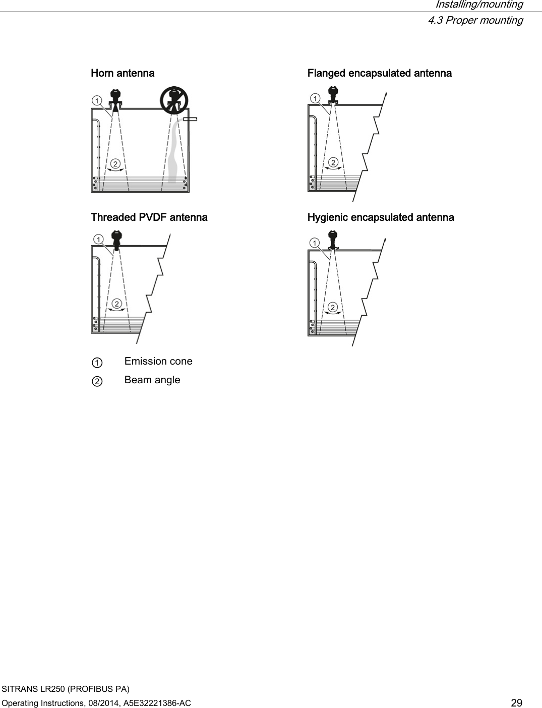
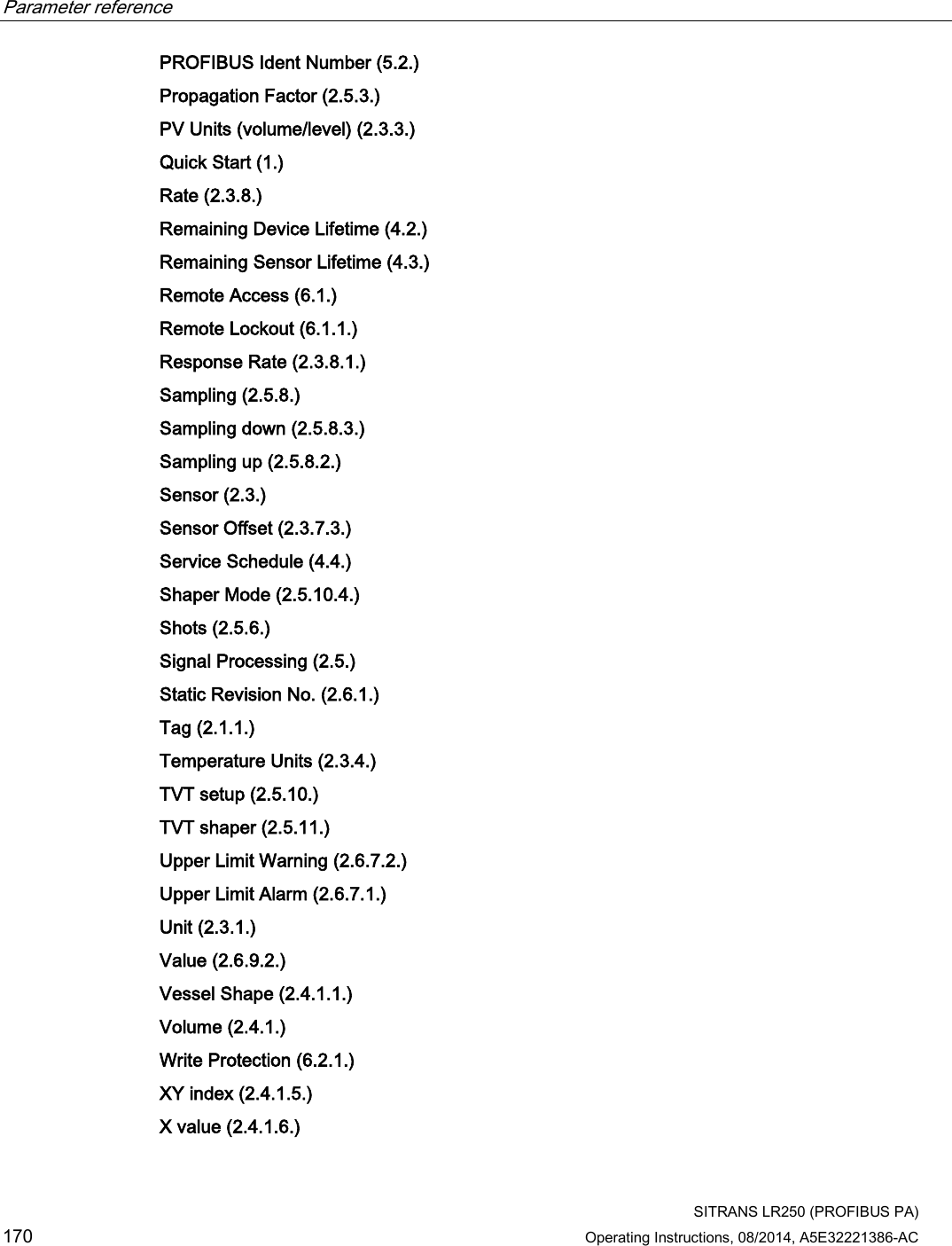
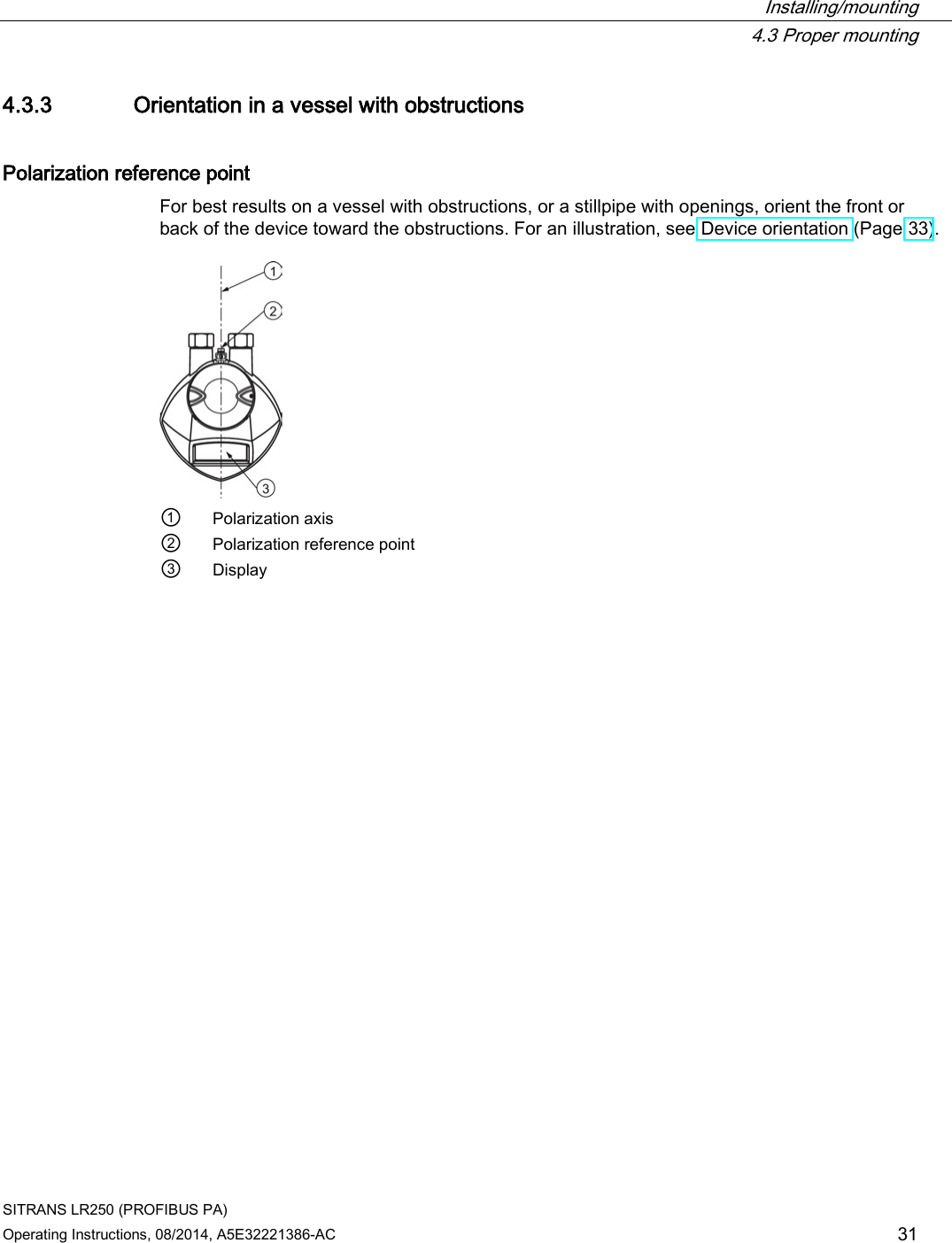
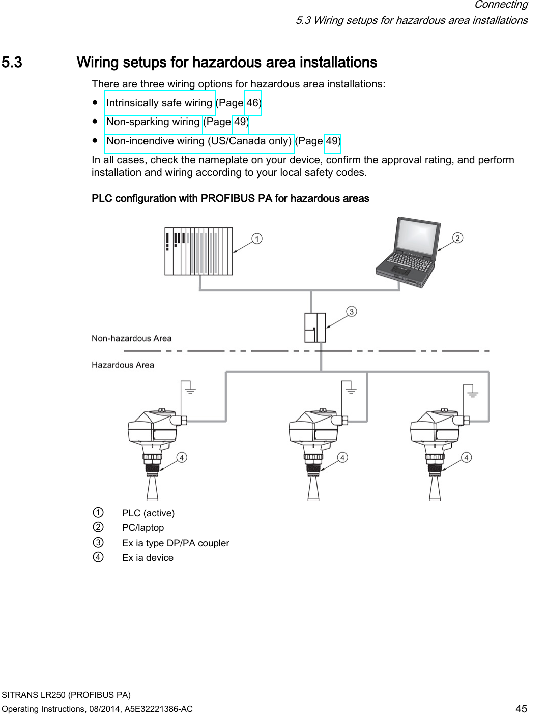
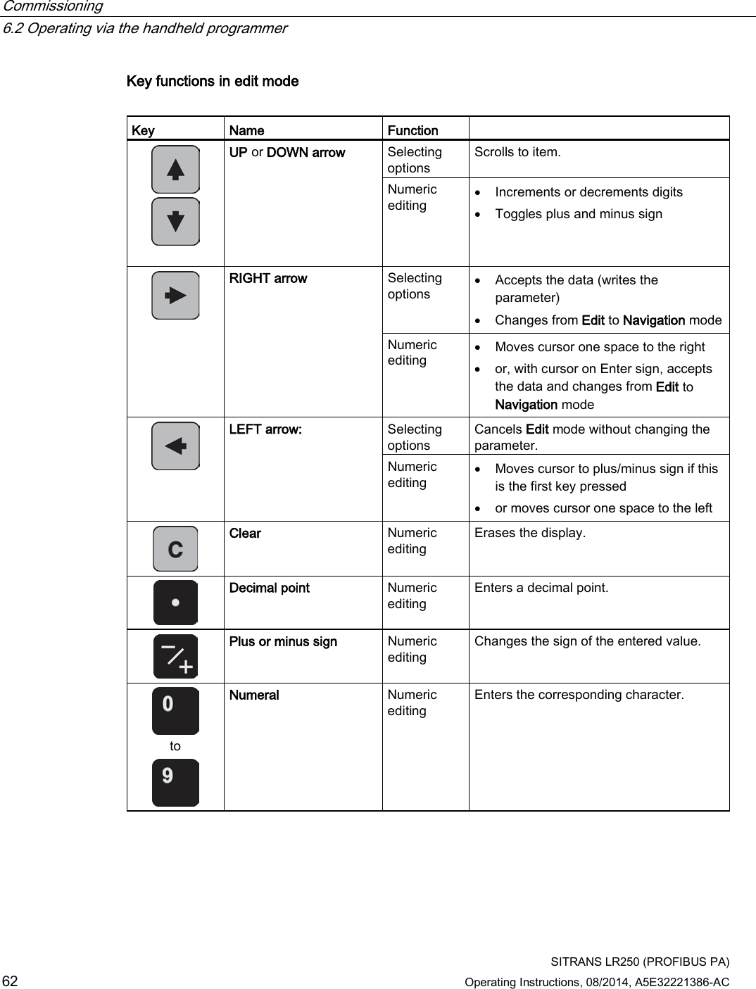
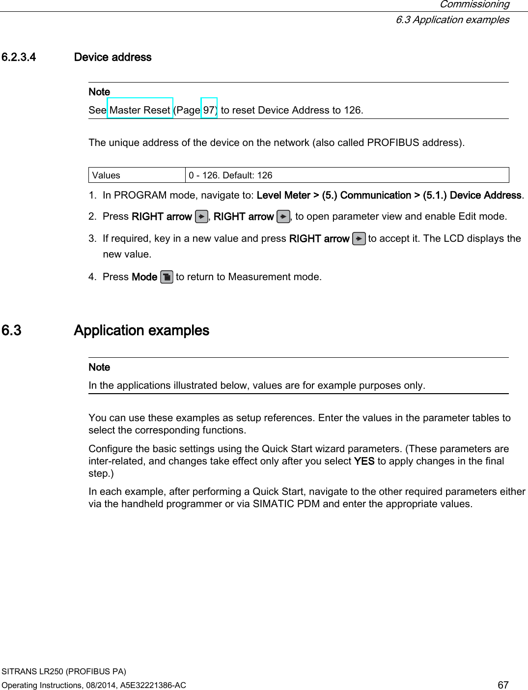
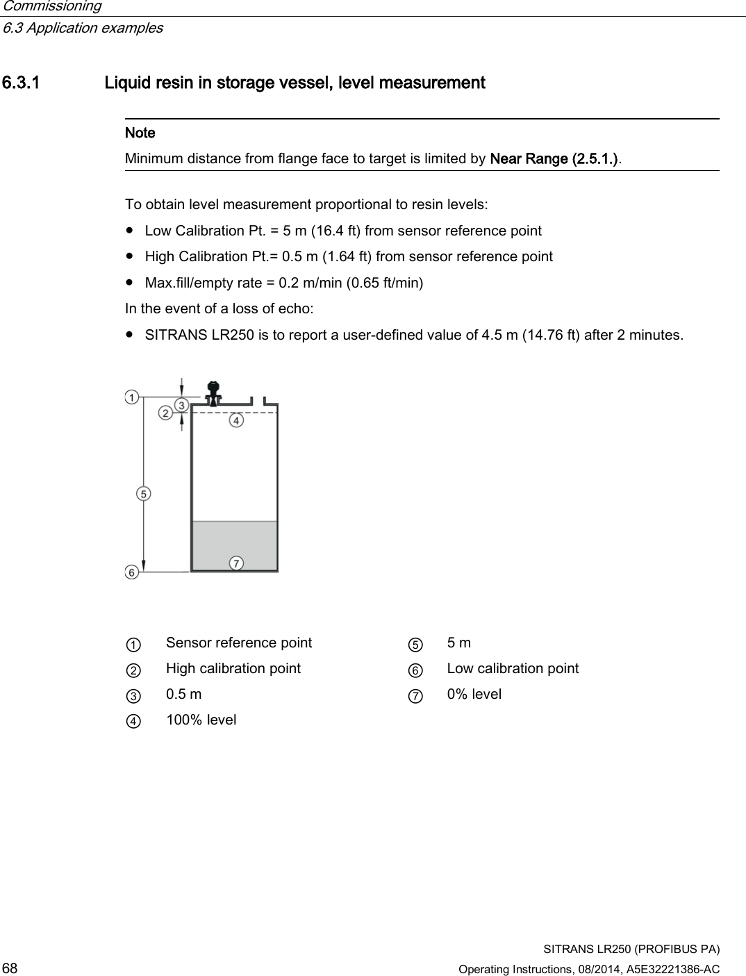
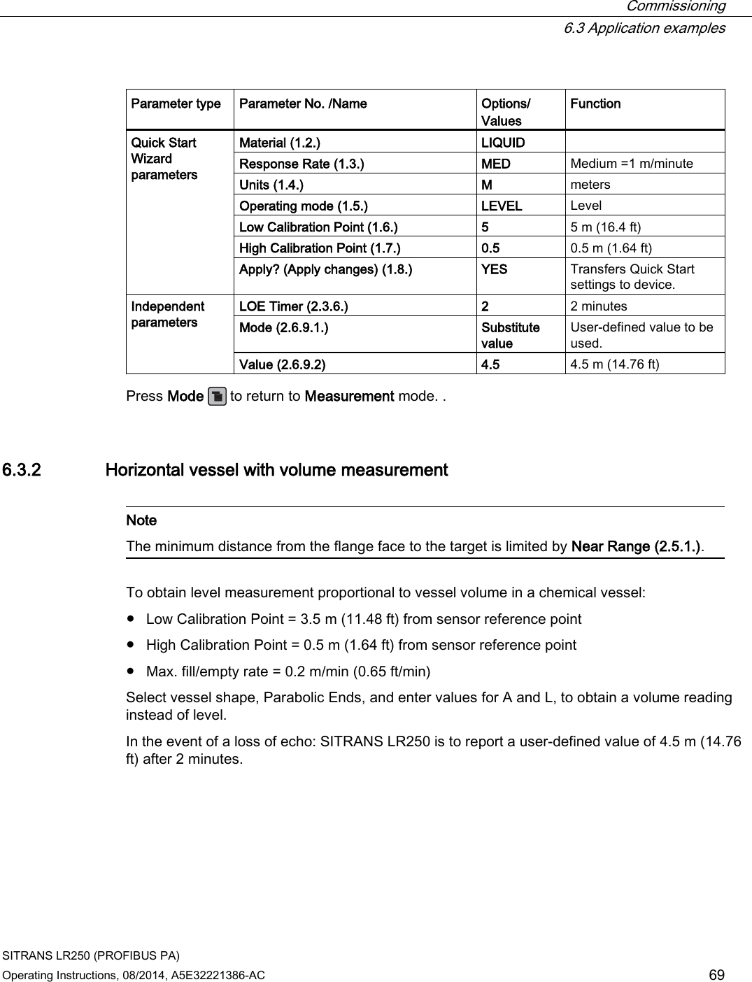
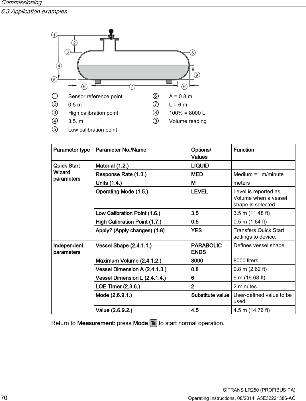
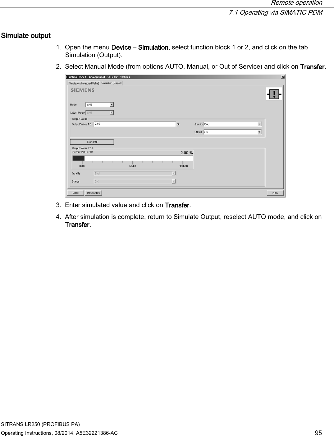
![Installing/mounting 4.3 Proper mounting SITRANS LR250 (PROFIBUS PA) 30 Operating Instructions, 08/2014, A5E32221386-AC Emission cone type and beam angle Antenna type Antenna size Beam angle Horn 1.5" 19° 2" 15° 3" 10° 4" 8° Threaded PVDF 19° Process connection size Process connection type Flanged encapsulated 2" Class 150 ASME B16.5 12.8° 3, 4, 6" Class 150 ASME B16.5 9.6° 50A 10K JIS B 2220 12.8° 80A/100A/150A 10K JIS B 2220 9.6° DN50 PN10/16 EN1092-1 12.8° DN80/DN100/DN150 PN10/16 EN1092-1 9.6° Hygienic encapsulated 2" Sanitary Clamp according to ISO 2852 12.8° 3, 4" 9.6° DN50 Aseptic/Hygienic nozzle/slotted nut according to DIN 11864-1 [Form A] 12.8° DN80/DN100 9.6° DN50 Aseptic/Hygienic flanged according to DIN 11864-2 [Form A] 12.8° DN80/DN100 9.6° DN50 Aseptic/Hygienic Clamp according to DIN 11864-3 [Form A] 12.8° DN80/DN100 9.6° DN50 Hygienic nozzle/slotted nut according to DIN 11851 12.8° DN80/DN100 9.6° Type F (50 mm) and Type N (68 mm) Tuchenhagen Varivent 12.8° Emission cone ● Keep emission cone free of interference from obstructions such as ladders, pipes, I-beams, or filling streams. Access for programming ● Provide easy access for viewing the display and programming via the handheld programmer.](https://usermanual.wiki/Siemens-Canada-Siemens-Milltronics-Process-Instruments/LR250.User-Manual-5/User-Guide-2277920-Page-30.png)


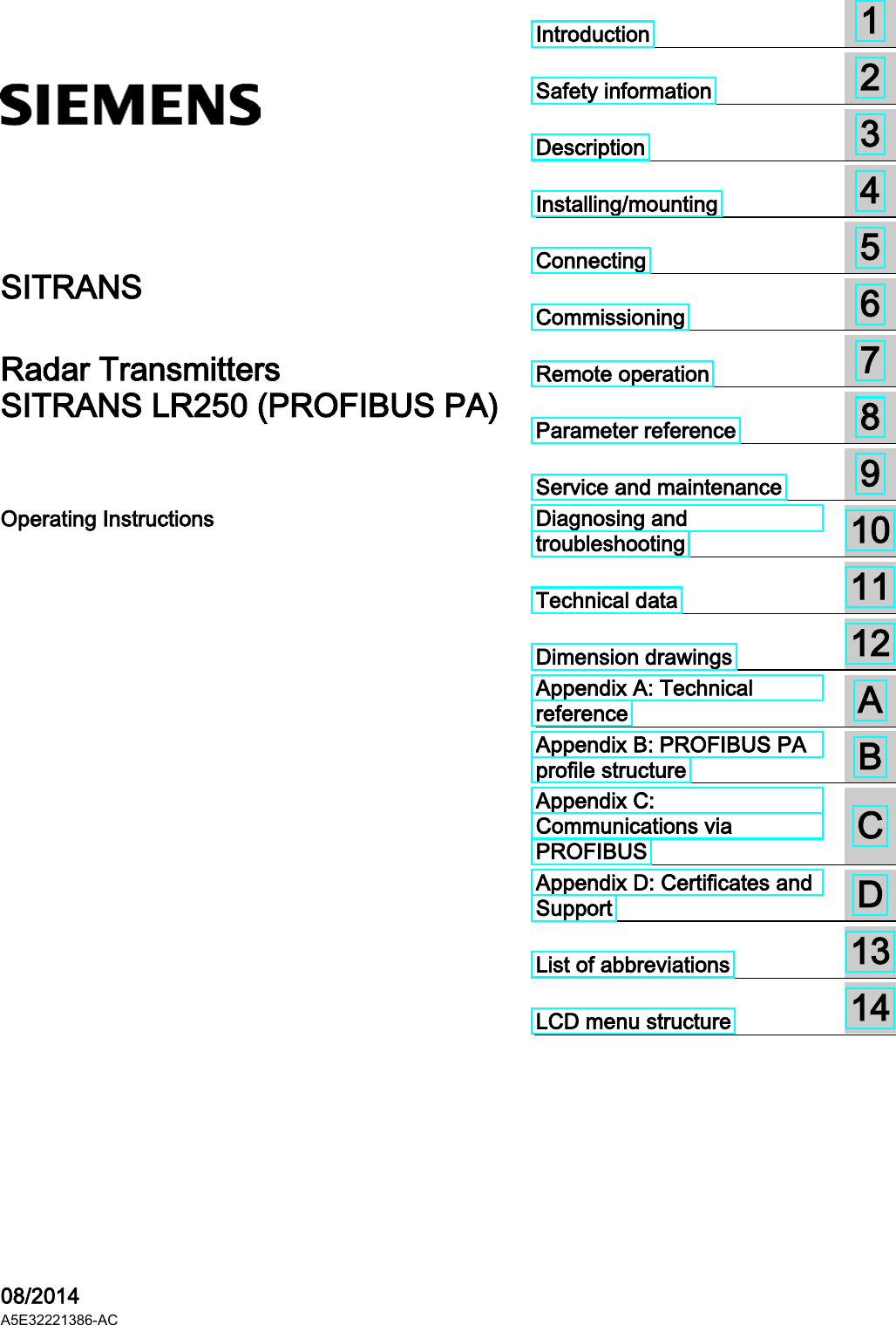
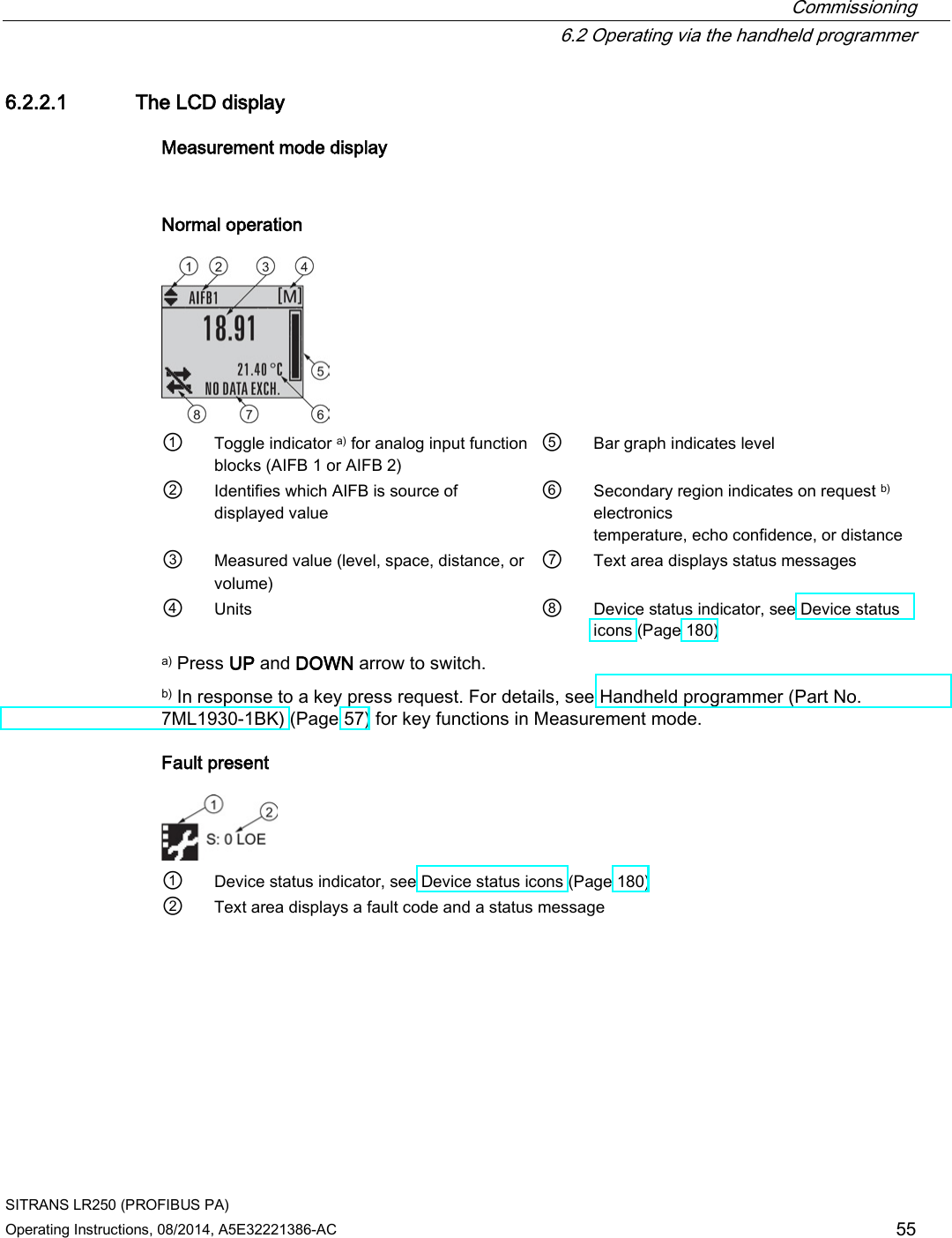
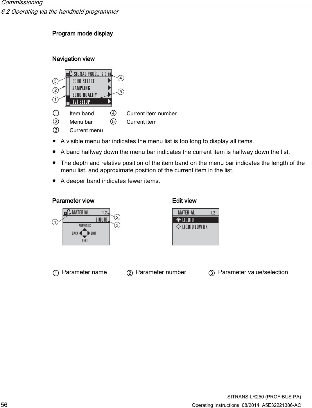
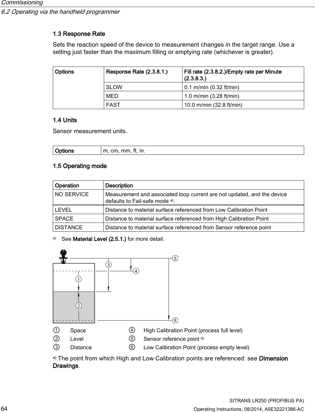
![Commissioning 6.2 Operating via the handheld programmer SITRANS LR250 (PROFIBUS PA) 54 Operating Instructions, 08/2014, A5E32221386-AC 6.2.1 Power up Power up the device. A transition screen showing first the Siemens logo and then the current firmware revision is displayed while the first measurement is being processed. Press Mode to toggle between Measurement and Program mode. 6.2.2 Handheld programmer functions The radar device carries out its level measurement tasks according to settings made via parameters. The settings can be modified locally via the Local User Interface (LUI) which consists of an LCD display and a handheld programmer. A Quick Start Wizard provides an easy step-by-step procedure to configure the device for a simple application. Access the wizards: ● locally [see Quick Start Wizard via the handheld programmer (Page 63)] ● or from a remote location [see Quick Start Wizard via SIMATIC PDM (Page 78)] For more complex setups see Application Examples (Page 67), and for the complete range of parameters see Parameter Reference (Page 107).](https://usermanual.wiki/Siemens-Canada-Siemens-Milltronics-Process-Instruments/LR250.User-Manual-5/User-Guide-2277920-Page-54.png)
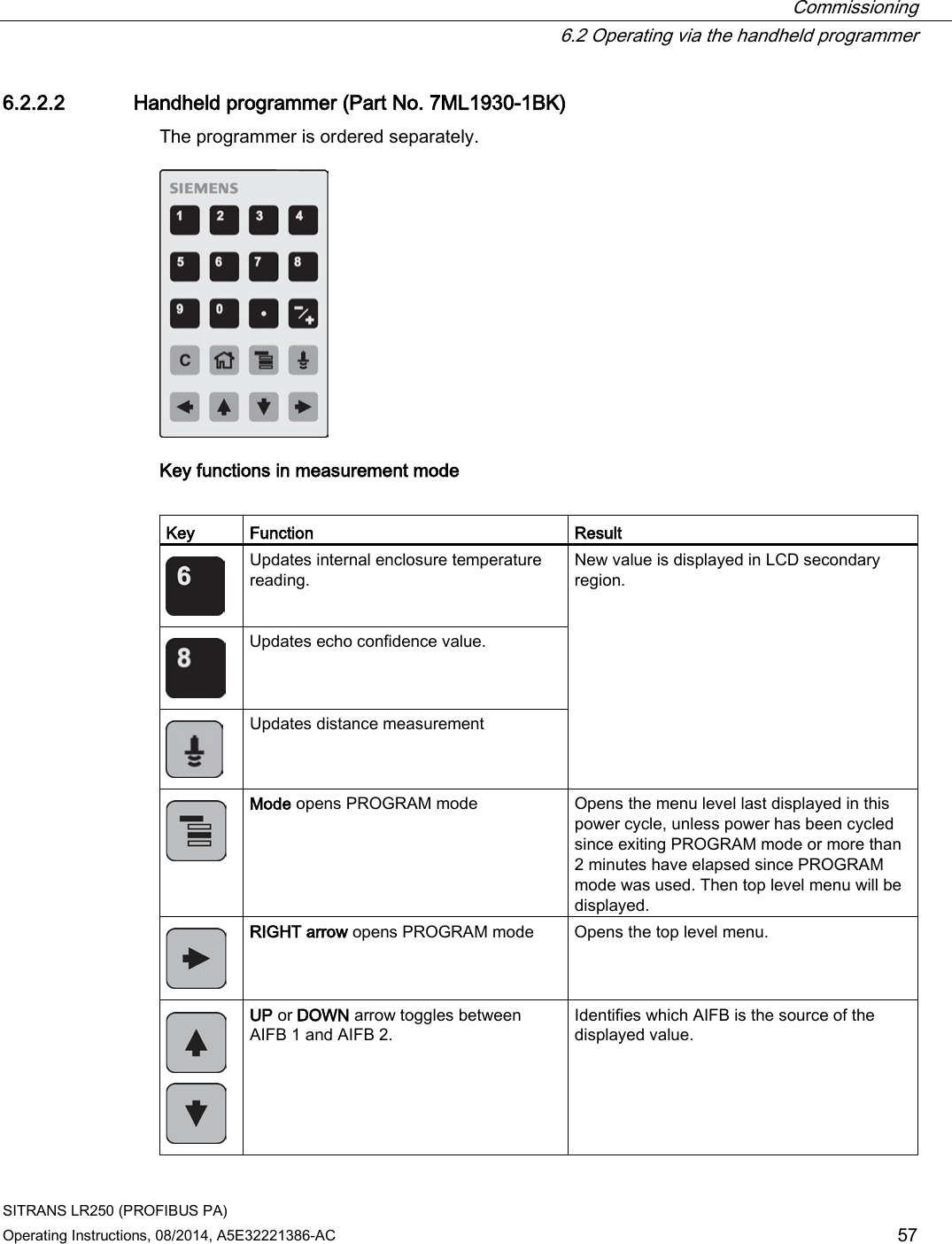
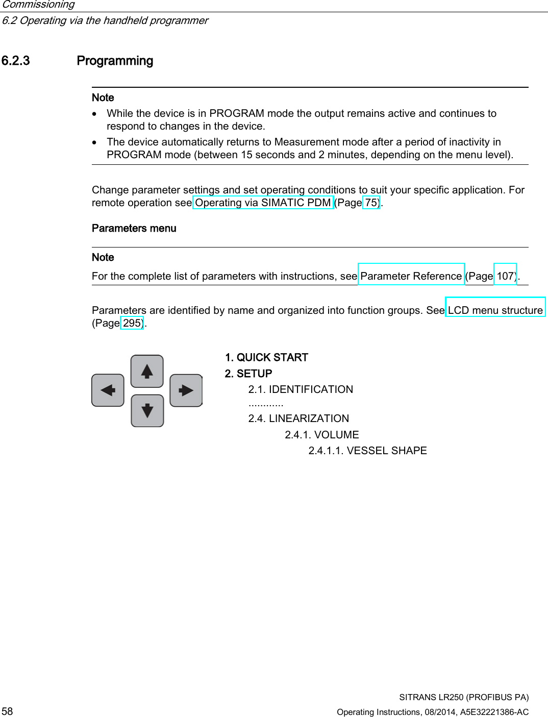
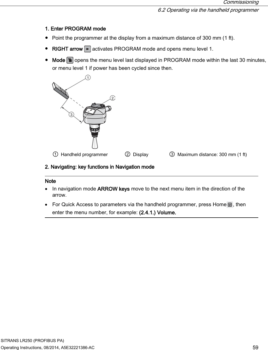
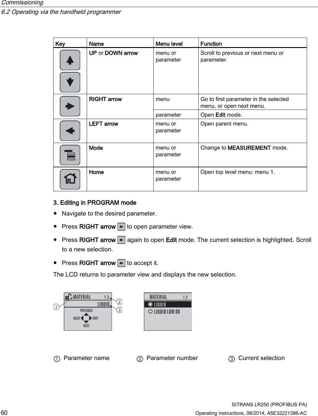
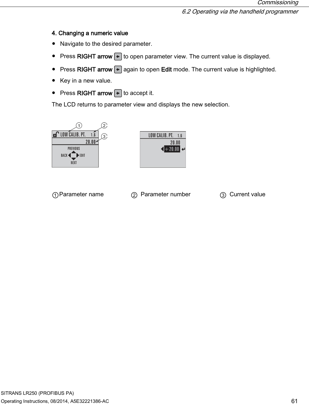
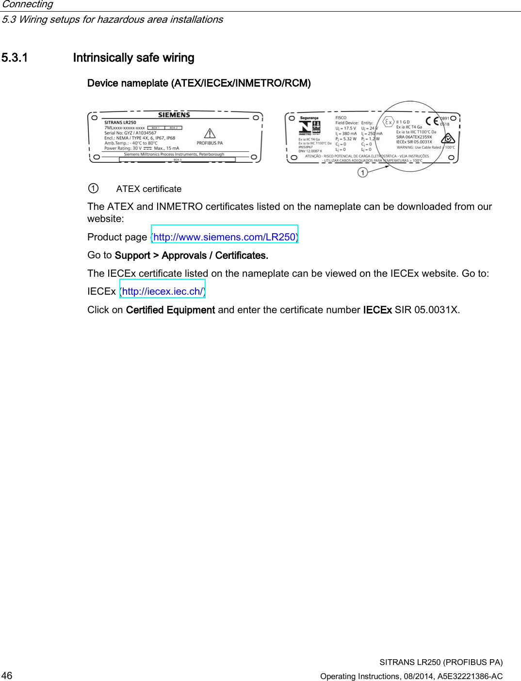
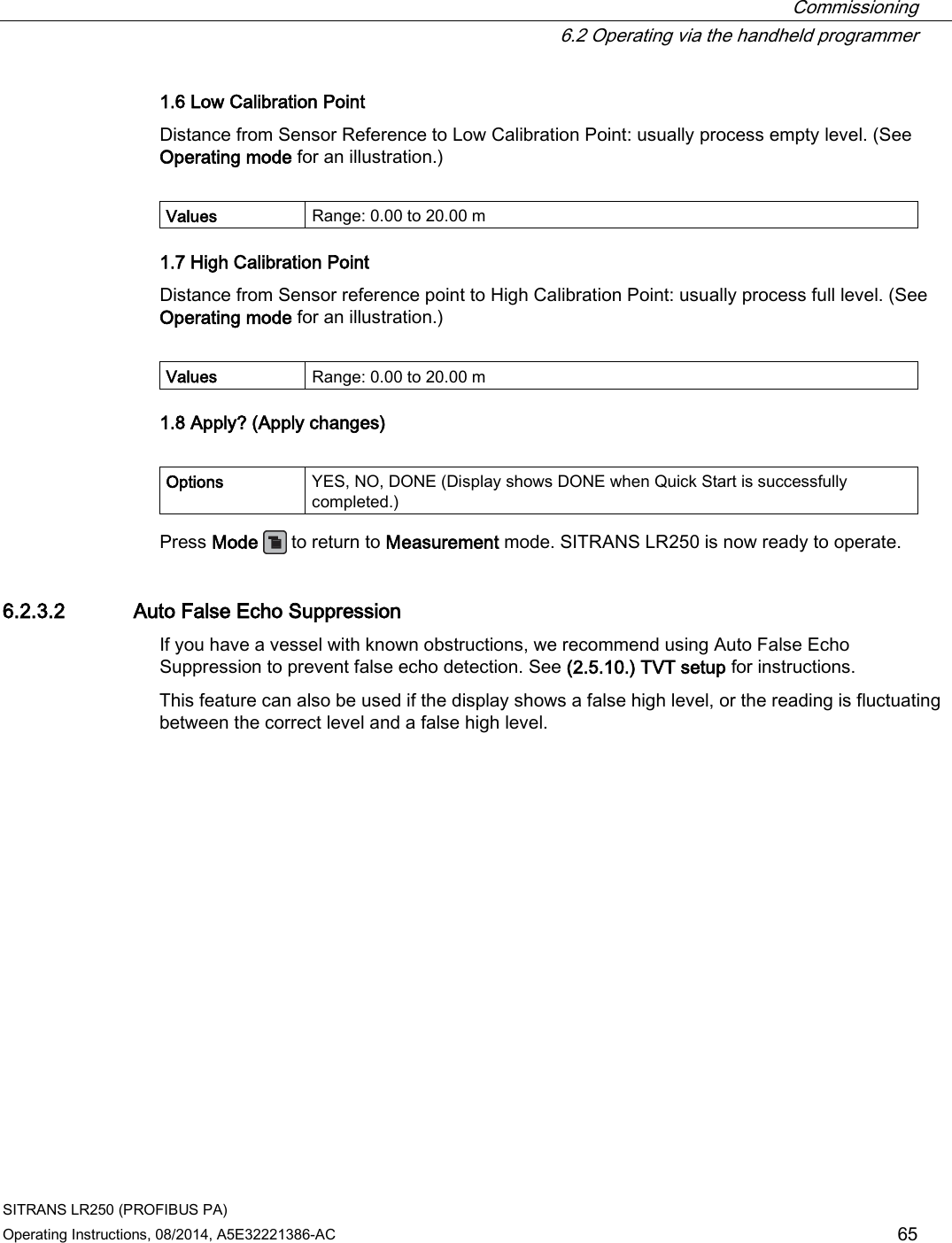
![Commissioning 6.2 Operating via the handheld programmer SITRANS LR250 (PROFIBUS PA) Operating Instructions, 08/2014, A5E32221386-AC 63 6.2.3.1 Quick Start Wizard via the handheld programmer Note • A reset to factory defaults should be performed before running the Quick Start Wizard if the device has been used in a previous application. See Master Reset (4.1.). • The Quick Start wizard settings are inter-related and changes apply only after you select YES in (1.8) Apply? (Apply changes) in the Wizard Complete step. • Do not use the Quick Start wizard to modify parameters: see instead Parameter reference (Page 107). (Perform customization for your application only after the Quick Start has been completed). • Default settings in the parameter tables are indicated with an asterisk (*). 1. Quick Start ● Point the programmer at the display from a maximum distance of 300 mm (1 ft), then press RIGHT arrow to activate PROGRAM mode and open menu level 1. ● Press RIGHT arrow twice to navigate to menu item 1.1 and open parameter view. ● Press RIGHT arrow to open Edit mode or DOWN arrow to accept default values and move directly to the next item. ● To change a setting, scroll to the desired item or key in a new value. ● After modifying a value, press RIGHT arrow to accept it and press DOWN arrow to move to the next item. ● Quick Start settings take effect only after you select Yes to Apply changes from previous steps. 1.1 Language Selects the language to be used on the LCD and takes effect immediately. Options English, Deutsch, Français, Español 1.2 Material Selects the appropriate echo processing algorithms for the material [see Position Detect (2.5.7.2.) for more detail]. Options * LIQUID LIQUID LOW DK a) (low dielectric liquid – CLEF algorithm enabled) a) dK < 3.0](https://usermanual.wiki/Siemens-Canada-Siemens-Milltronics-Process-Instruments/LR250.User-Manual-5/User-Guide-2277920-Page-63.png)
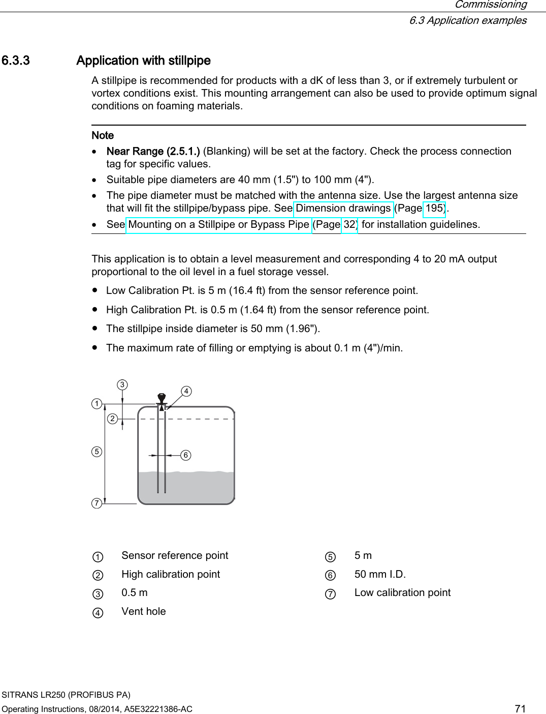

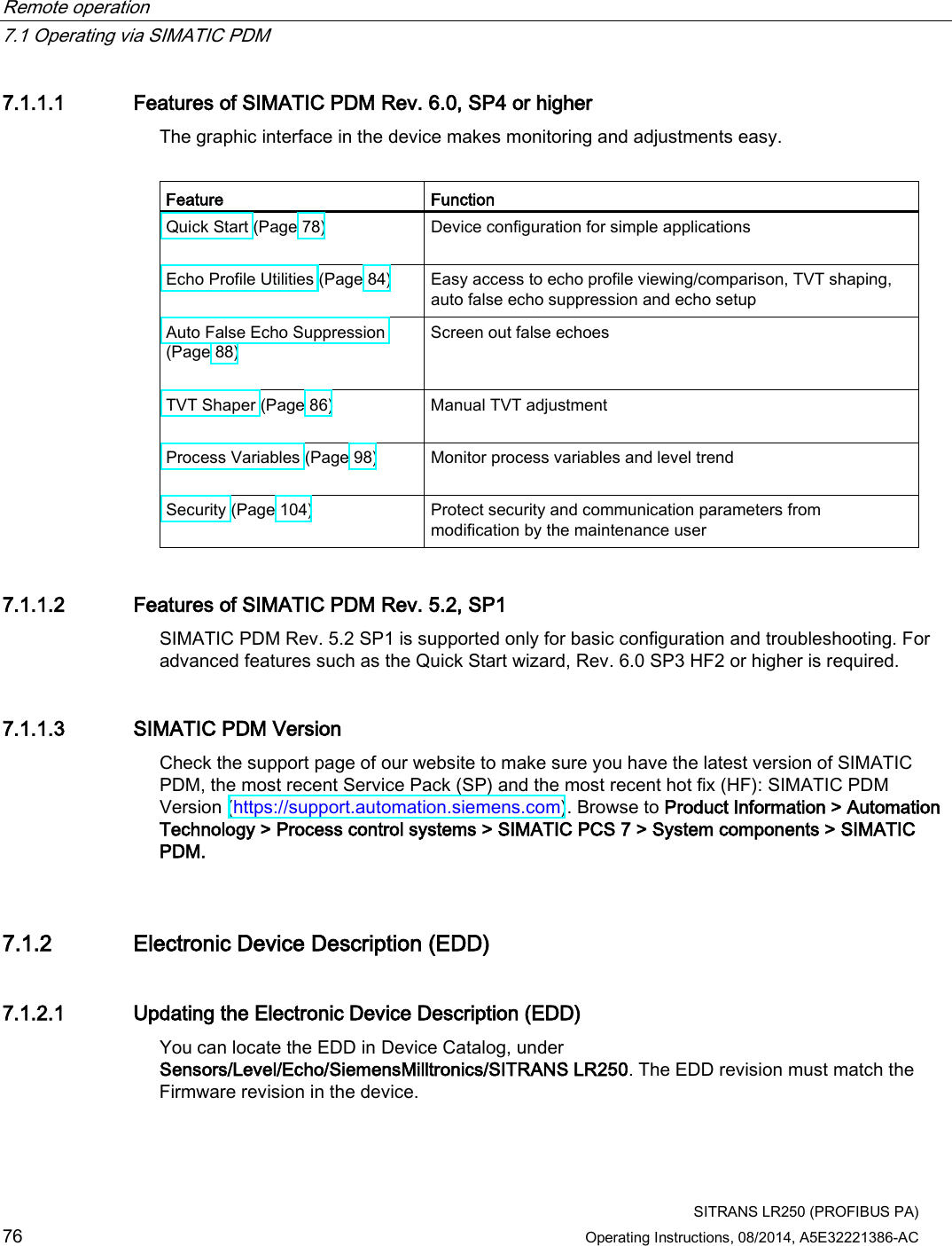
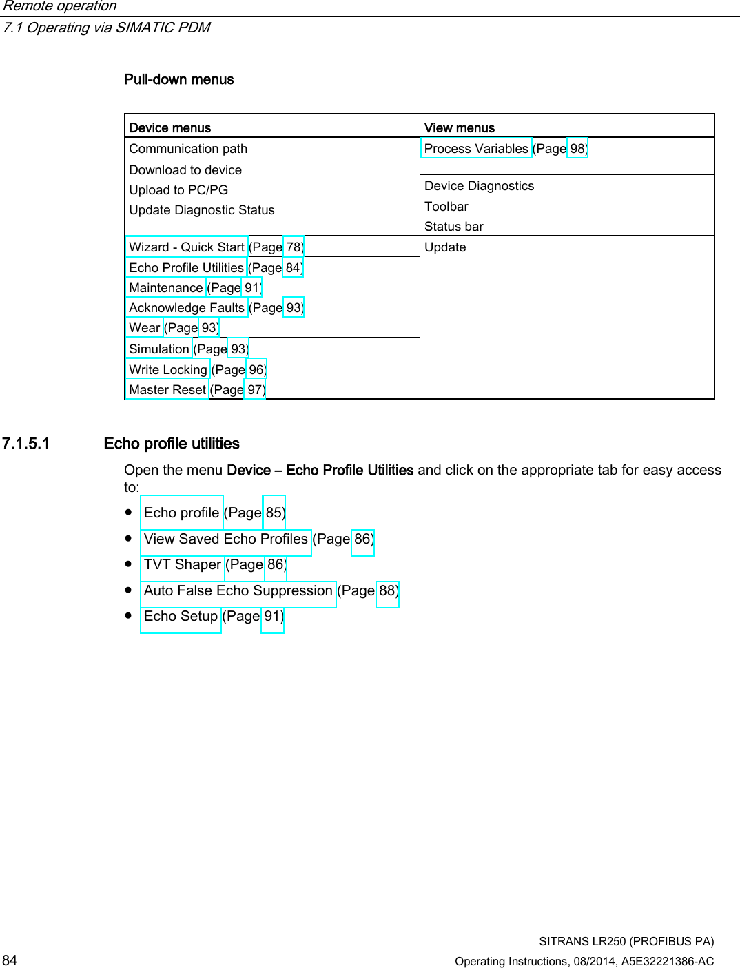
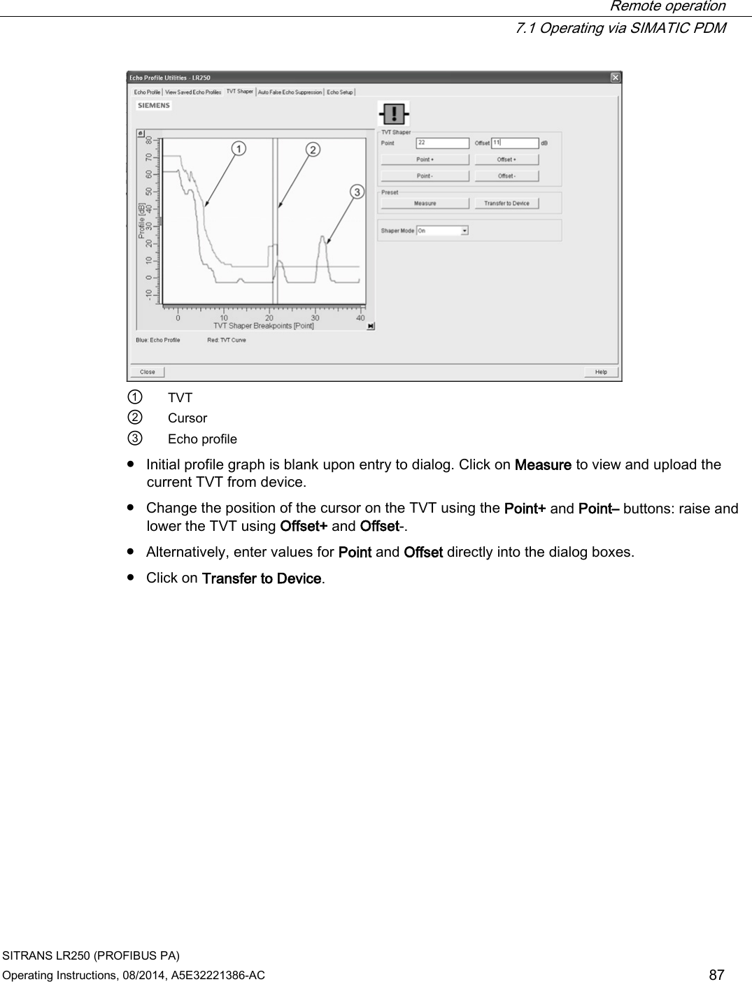
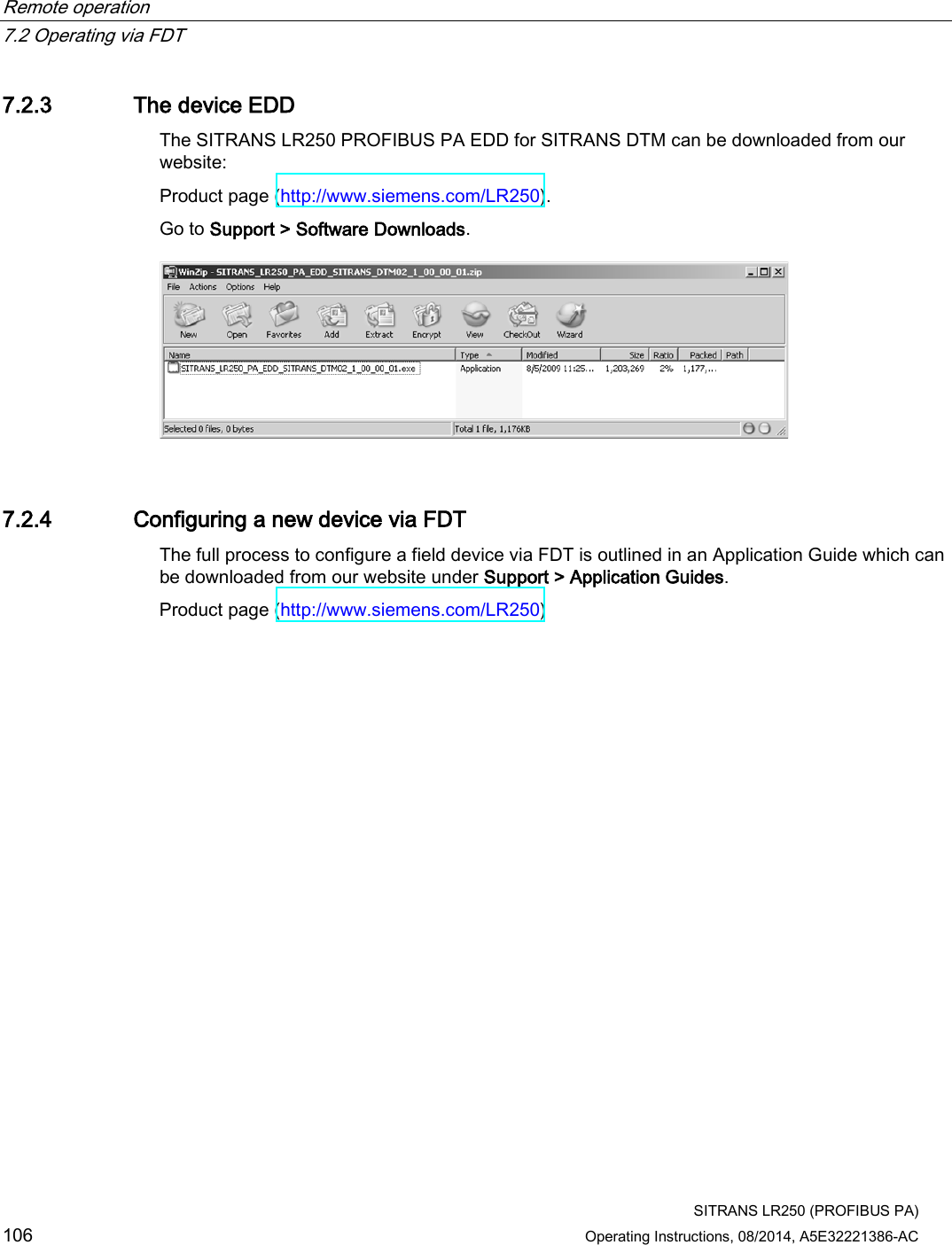
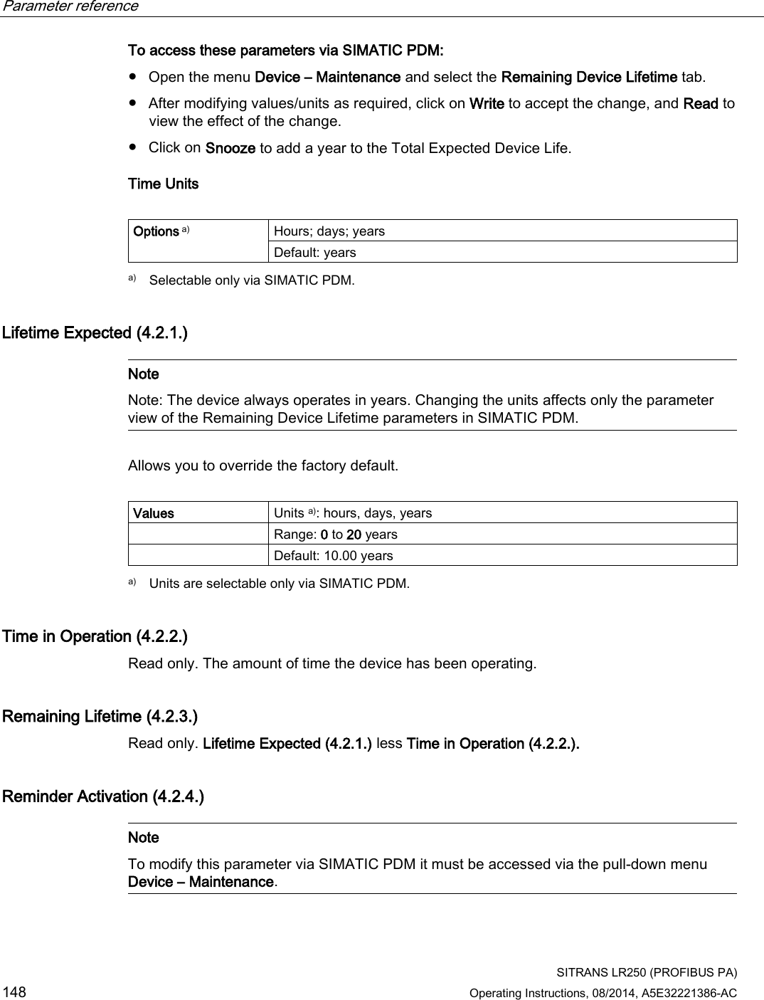
![Remote operation 7.1 Operating via SIMATIC PDM SITRANS LR250 (PROFIBUS PA) Operating Instructions, 08/2014, A5E32221386-AC 77 To install a new EDD: 1. Download the most current EDD from our website: Product page (http://www.siemens.com/LR250) 2. Save files to your computer, and extract the zipped file to an easily accessed location. 3. Launch SIMATIC PDM – Manage Device Catalog, browse to the unzipped EDD file and select it. 7.1.2.2 Configuring a new device Note • Clicking on Cancel during an upload from device to SIMATIC PDM will result in some parameters being updated. • Application Guides for setting up PROFIBUS PA devices with SIMATIC PDM can be downloaded from our website: Product page (http://www.siemens.com/LR250). 1. Check that you have the most recent EDD, and if necessary update it. [See Updating the Electronic Device Description (EDD) (Page 76)]. 2. Set Address via handheld programmer (default for PROFIBUS PA is 126). [See Device Address (5.1.) to use SIMATIC PDM.] – In PROGRAM mode, navigate to: Level Meter > Communication (5.) > Device Address (5.1.). – Press RIGHT arrow , RIGHT arrow , to open parameter view and enable Edit mode. – If required, key in a new value and press RIGHT arrow to accept it. The LCD displays the new value. – Press Mode to return to Measurement mode. 3. Launch SIMATIC Manager and create a new project for the device. 4. Open the menu Device – Master Reset and click on Factory Defaults. 5. After the reset is complete click on Close, then upload parameters to the PC/PG. 6. Configure the device via the Quick Start wizard.](https://usermanual.wiki/Siemens-Canada-Siemens-Milltronics-Process-Instruments/LR250.User-Manual-5/User-Guide-2277920-Page-77.png)
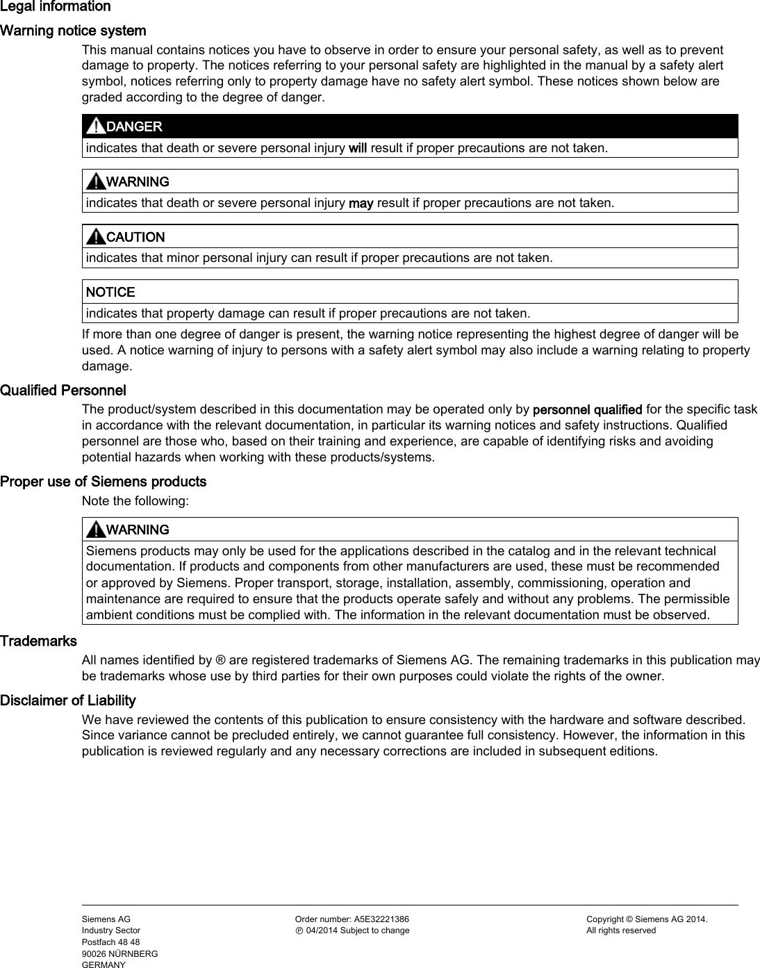
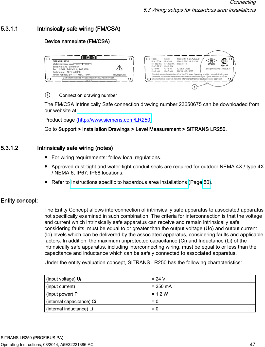
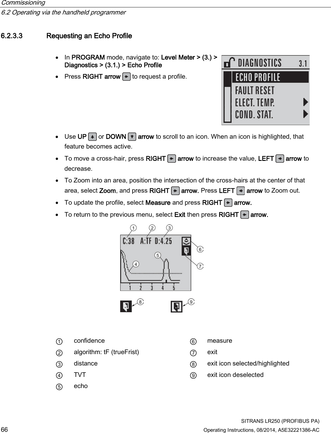
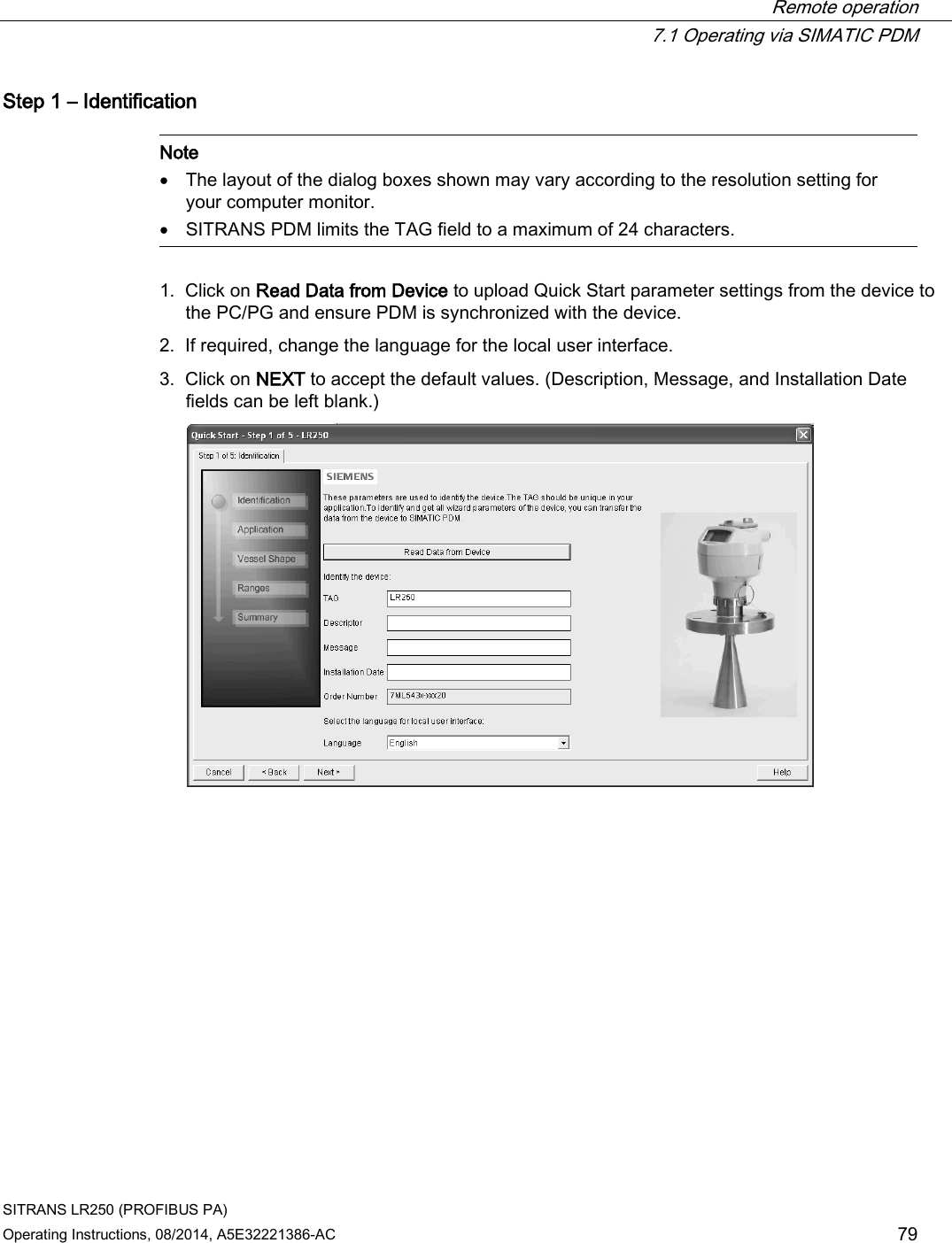
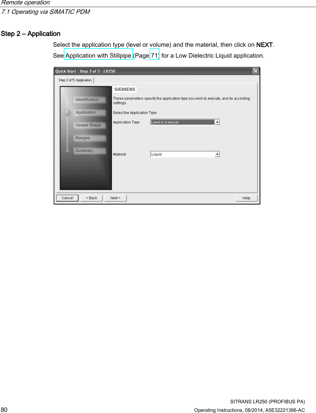
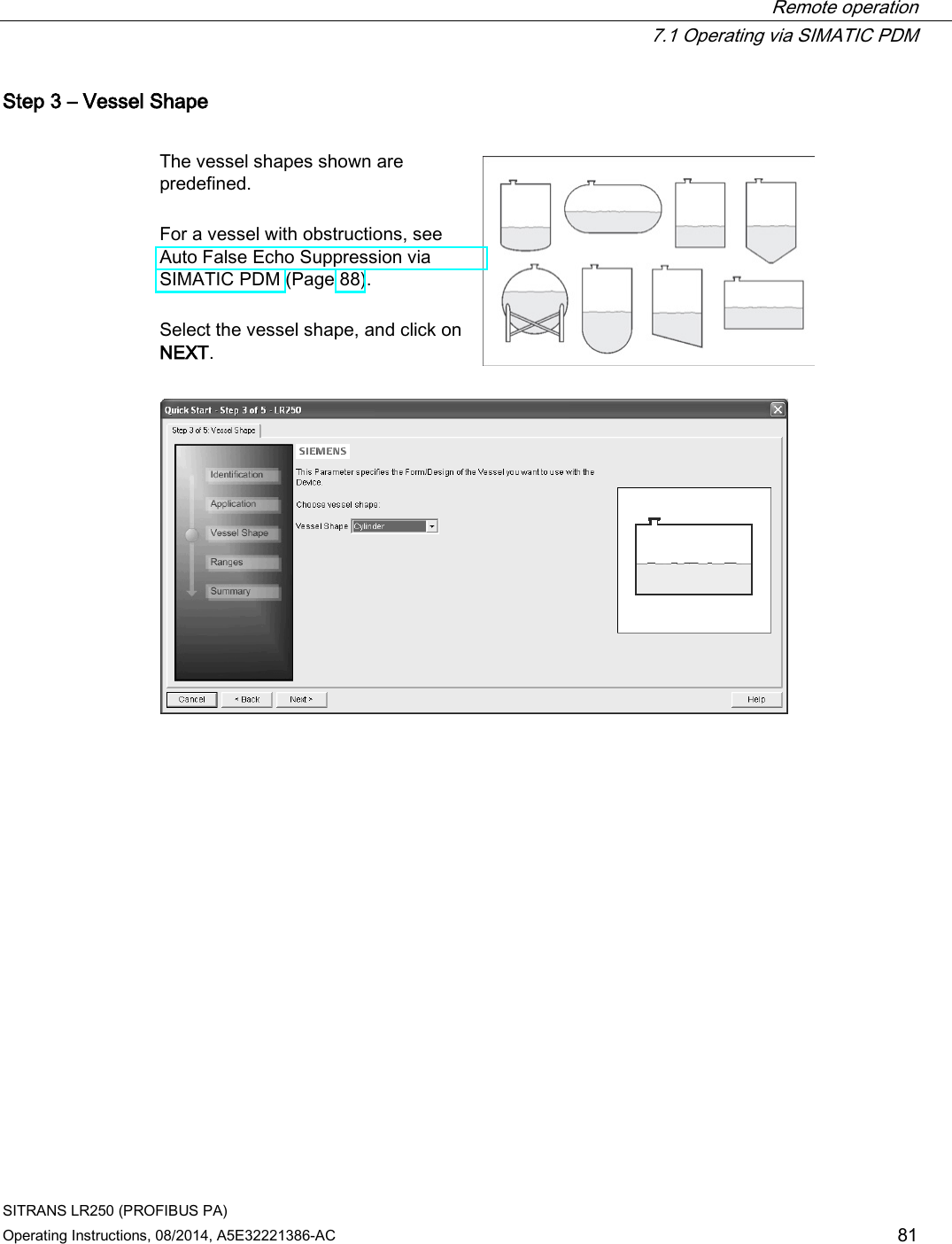
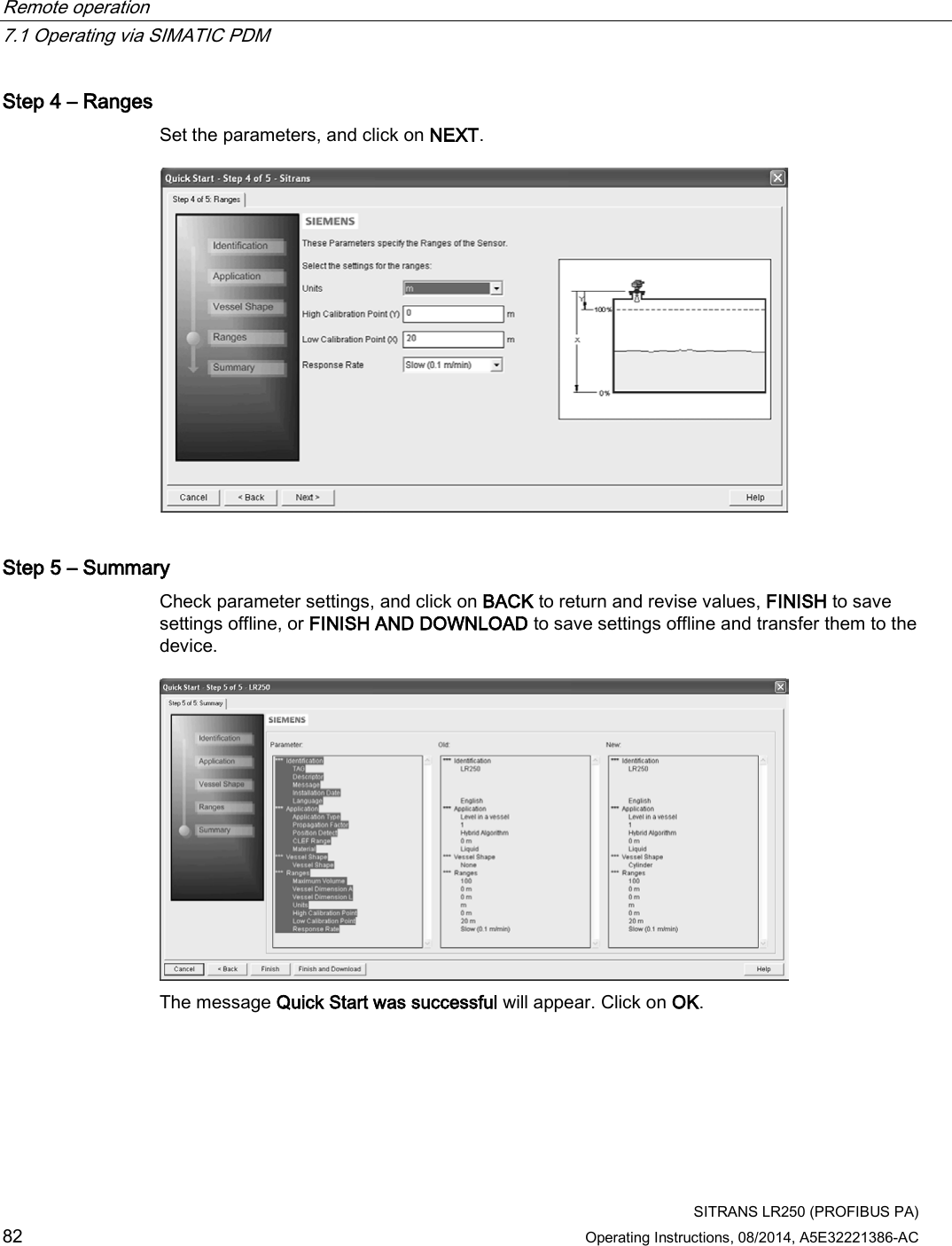
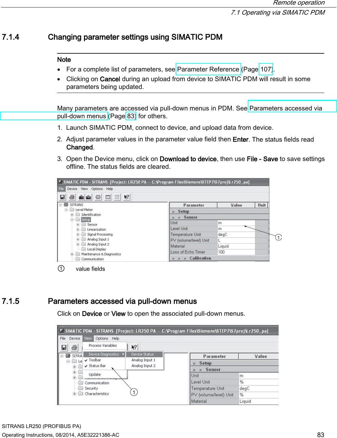
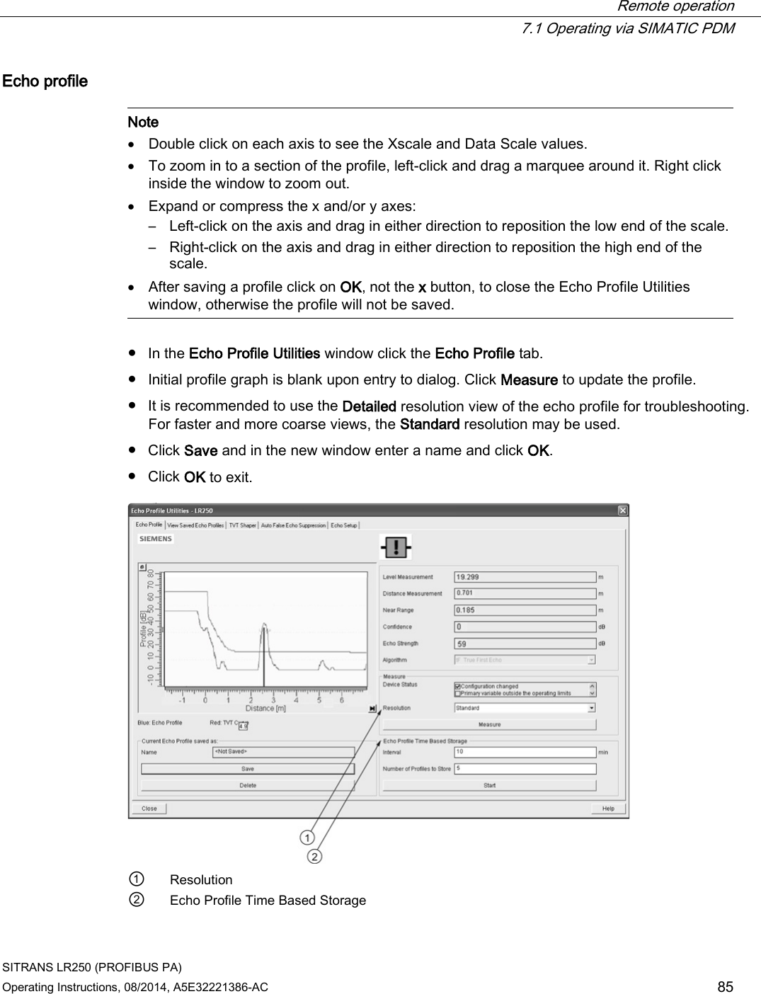
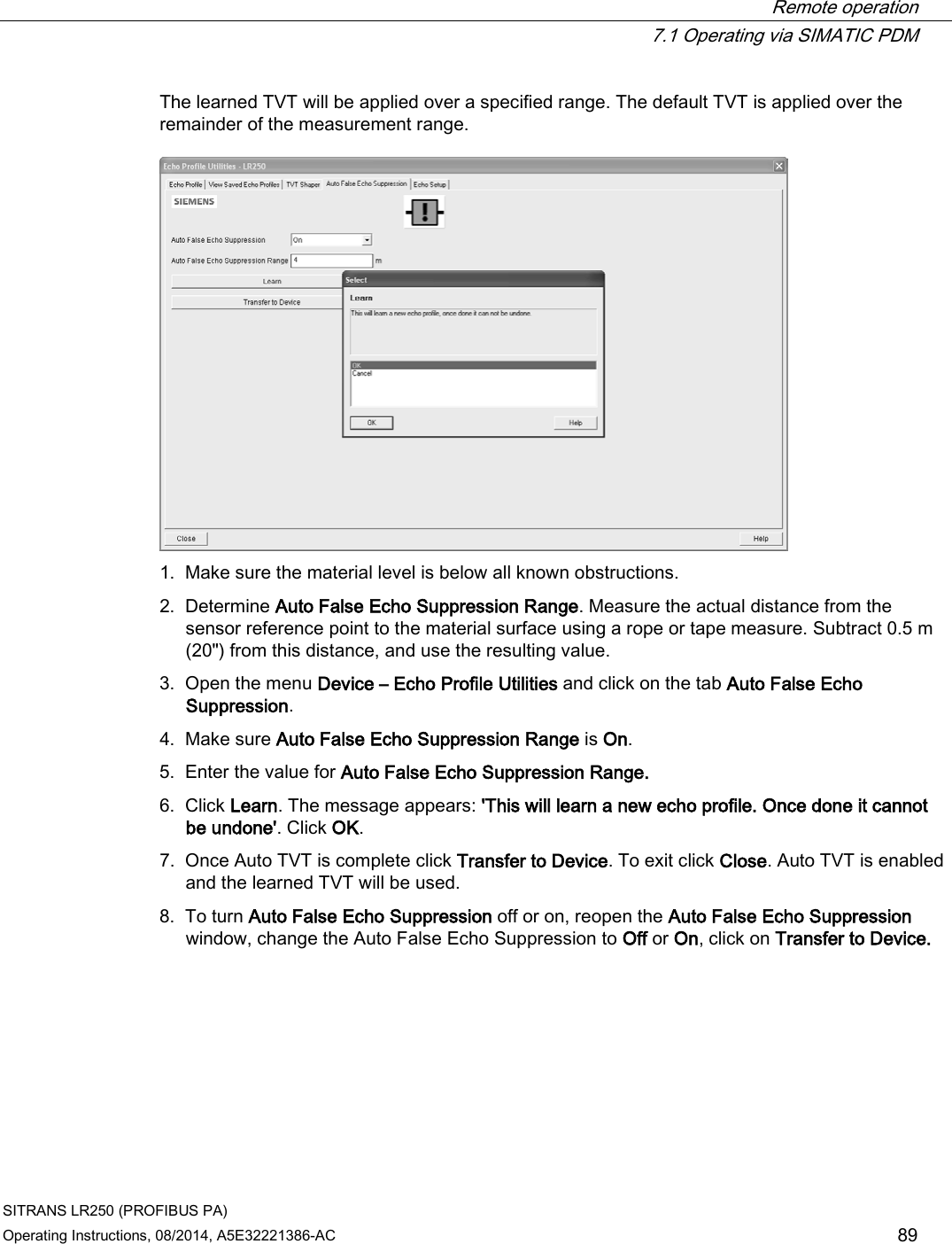
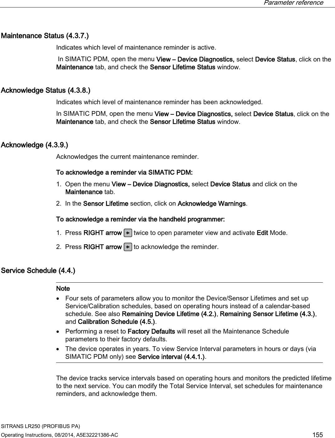
![Remote operation 7.1 Operating via SIMATIC PDM SITRANS LR250 (PROFIBUS PA) 78 Operating Instructions, 08/2014, A5E32221386-AC 7.1.3 Quick start wizard via SIMATIC PDM The graphic Quick Start Wizard provides an easy step-by-step procedure that configures the device for a simple application. Please consult the operating instructions or online help for details on using SIMATIC PDM. 1. If you have not already done so, check that you have the most up-to-date Electronic Device Description (EDD) for your device. [See Configuring a new device (Page 77).] 2. Launch SIMATIC Manager and create a new project. Application Guides for setting up HART and PROFIBUS PA devices with SIMATIC PDM can be downloaded from the product page of our website: Product page (http://www.siemens.com/LR250) Quick start Note • A reset to Factory Defaults should be performed before running the Quick Start Wizard if device has been used in a previous application. See Master Reset via SIMATIC PDM (Page 97). • The Quick Start wizard settings are inter-related and changes apply only after you click on FINISH AND DOWNLOAD at the end of the last step to save settings offline and transfer them to the device. • Do not use the Quick Start Wizard to modify individual parameters: for quick access to echo profile parameters, see Echo Profile via SIMATIC PDM (Page 85) or see Parameter Reference (Page 107) for a complete list. (Perform customization only after the Quick Start has been completed.) • Click on BACK to return and revise settings or CANCEL to exit the Quick Start. • For a vessel with obstructions see Auto False Echo Suppression via SIMATIC PDM (Page 88). Launch SIMATIC PDM, open the menu Device – Wizard - Quick Start, and follow steps 1 to 5. ① Quick Start](https://usermanual.wiki/Siemens-Canada-Siemens-Milltronics-Process-Instruments/LR250.User-Manual-5/User-Guide-2277920-Page-78.png)
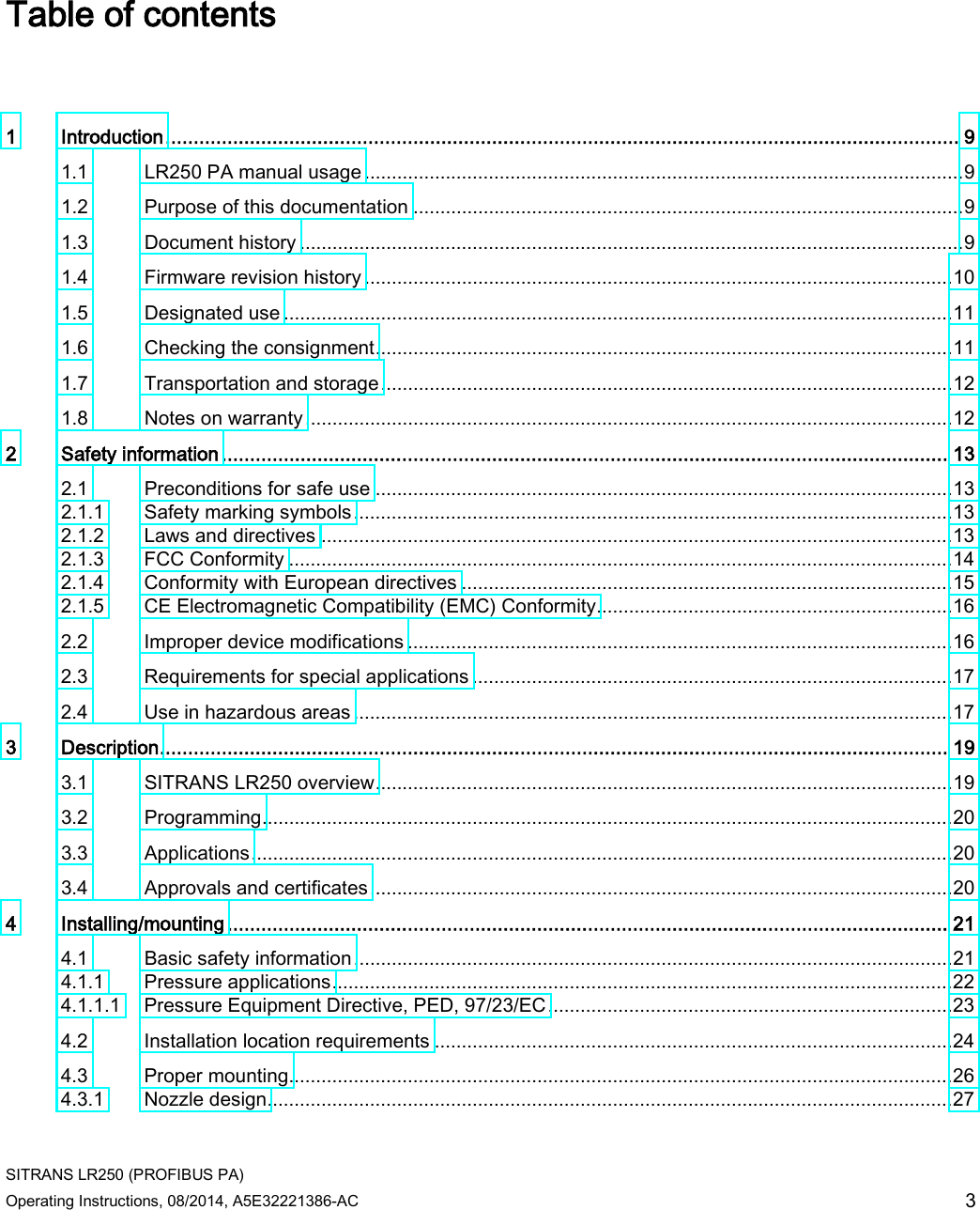
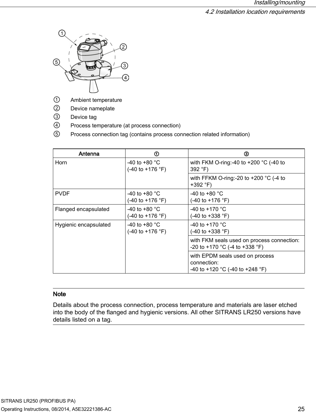
![Parameter reference SITRANS LR250 (PROFIBUS PA) 112 Operating Instructions, 08/2014, A5E32221386-AC ① High level point (default: 100%) ⑥ Level offset (if used) ② Low level point (default: 0%) ⑦ Low calibration point a) ③ Sensor value ⑧ Sensor reference point ④ High calibration point ⑨ Far range ⑤ Level a) Sensor reference point is the point from which level measurement is referenced. See Threaded Horn Antenna with extension (Page 195), Flanged Horn with extension (Page 200), and Flanged encapsulated antenna (3"/DN80/80A sizes and larger). (Page 206) Values Range: 0 to 20 m. Default 20.00 m Related parameters Unit (2.3.1.), Far Range (2.5.2.) High Calibration Pt. (2.3.7.2.) Distance from sensor reference point 1) to High Calibration Point (corresponding to High Level Point). Units are defined in Unit (2.3.1.). Values Range: 0 to 20 m. Default 0.00 m Related parameters Unit (2.3.1.), Near Range (2.5.1.) When setting the High Calibration Point value, note that echoes are ignored within Near Range (2.5.1.). 1) The value produced by the echo processing which represents the distance from sensor reference point to the target. [see Threaded Horn Antenna with extension, (Page 198) Flanged Horn with extension (Page 202), and Flanged encapsulated antenna (3"/DN80/80A sizes and larger) (Page 206)].](https://usermanual.wiki/Siemens-Canada-Siemens-Milltronics-Process-Instruments/LR250.User-Manual-5/User-Guide-2277920-Page-112.png)
![Parameter reference SITRANS LR250 (PROFIBUS PA) Operating Instructions, 08/2014, A5E32221386-AC 117 Vessel Shape LCD DISPLAY/ Description Also required FLAT SLOPED BOT/ Flat sloped bottom Maximum volume, dimension A PARABOLIC ENDS/ Parabolic end horizontal cylinder Maximum volume, dimension A, dimension L LINEAR TABLE a) / Linearization table (level/volume breakpoints) Maximum volume, tables 1-32 level and volume breakpoints a) Linearization Table must be selected in order for level/volume values [see XY index (2.4.1.5.)] to be transferred.](https://usermanual.wiki/Siemens-Canada-Siemens-Milltronics-Process-Instruments/LR250.User-Manual-5/User-Guide-2277920-Page-117.png)
![Parameter reference SITRANS LR250 (PROFIBUS PA) Operating Instructions, 08/2014, A5E32221386-AC 121 Signal Processing (2.5.) Note Default settings in the parameter tables are indicated with an asterisk (*) unless explicitly stated. Near Range (2.5.1.) The range in front of the device (measured from the sensor reference point) within which any echoes will be ignored. (This is sometimes referred to as blanking or a dead zone.) The factory setting is 50 mm (2") past the end of the antenna, and the default is dependent on the antenna type and process connection. [See Dimension drawings (Page 195) for antenna heights.] Values Range: 0 to 20 m (0 to 65.6 ft) Default depends on antenna type and process connection. Examples: 1.5" threaded horn 185.3 mm (7.3") 4" horn with stainless steel flange 100 mm (4") extension 373.3 mm (14.7") Related parameters Units (2.3.1.) Far Range (2.5.2.) Note Far Range can extend beyond the bottom of the vessel. Allows the material level to drop below Low Calibration Point without generating a Loss of Echo (LOE) state. See Low Calibration Pt. (2.3.7.1.) for an illustration. Values Range: Min. = Low Calibration Pt. Max. = 23 m (75.45 ft) Default: Value for Low Calibration Pt. + 1 m (3.28 ft) Related parameters Units (2.3.1.) Use this feature if the measured surface can drop below the Low calibration point in normal operation.](https://usermanual.wiki/Siemens-Canada-Siemens-Milltronics-Process-Instruments/LR250.User-Manual-5/User-Guide-2277920-Page-121.png)
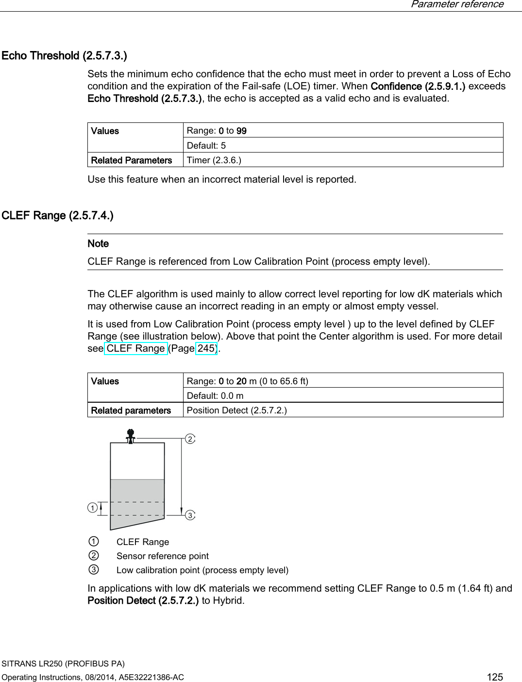
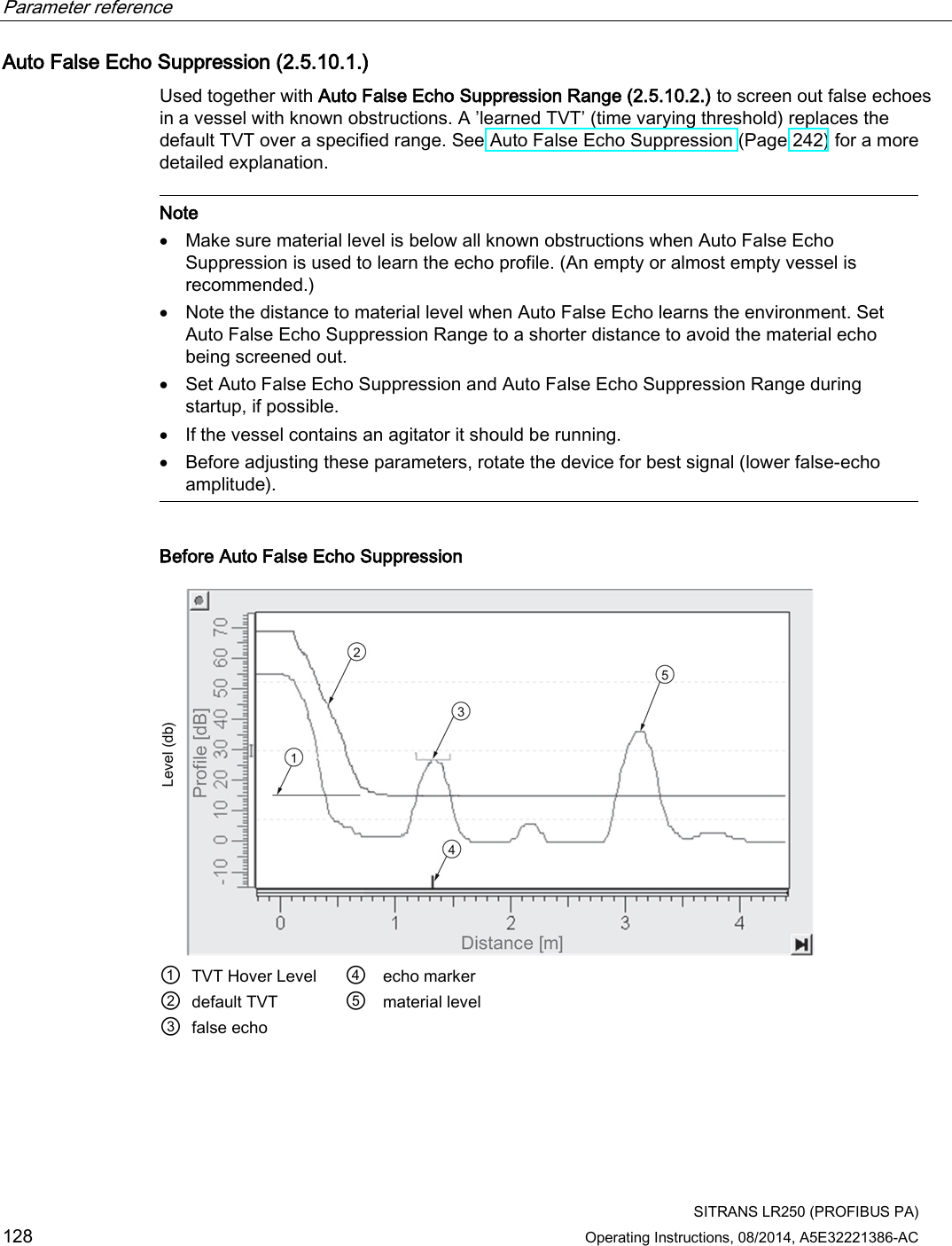
![Parameter reference SITRANS LR250 (PROFIBUS PA) Operating Instructions, 08/2014, A5E32221386-AC 139 Echo Profile (3.1.) To request a profile via SIMATIC PDM: Open the menu Device – Echo Profile Utilities. [See Echo Profile Utilities via SIMATIC PDM (Page 84) for more detail.] To request a profile via the handheld programmer: ① Echo confidence value ⑥ Measure icon, deselected ② Algorithm selection (tFirst echo) ⑦ Exit icon, selected ③ Distance value ⑧ Measure icon, selected ④ TVT curve ⑨ Exit icon, deselected ⑤ Material level 1. Navigate to Level Meter > Diagnostics (3.) > Echo Profile (3.1.). 2. Press RIGHT arrow to request a profile. [See Requesting an Echo Profile (Page 66) for more details.]](https://usermanual.wiki/Siemens-Canada-Siemens-Milltronics-Process-Instruments/LR250.User-Manual-5/User-Guide-2277920-Page-139.png)
![Parameter reference SITRANS LR250 (PROFIBUS PA) Operating Instructions, 08/2014, A5E32221386-AC 165 Device Address (5.1.) Note The address can be changed and locked from a remote master. See PROFIBUS address (Page 276) for details on disabling the address lock and Master Reset (4.1.) to reset Device Address to 126. Sets the unique address of the device on the network (also called PROFIBUS address). Values 0 - 126. Default: 126 To set Device Address via SIMATIC PDM: ● Open the project in Process Device Network View then right-click on the device. ● Go to Object Properties > Connection to access the field Short Address. To change Device Address via the handheld programmer: See Device Address for details. PROFIBUS Ident Number (5.2.) Identifies the device on the network. The Ident Number must match that in the GSD file (the GSD file provides information on the device to the master). Options STD PROFILE Standard Profile (uses generic GSD for 2 AIFB) [ident # = 0x9701] * MANUFACTURER Manufacturer-specific (uses Siemens EDD and GSD file, which identifies the LR250 PROFIBUS PA [ident # = 0x8150] STD – AIFB 1 ONL. Standard Profile AIFB 1 only (uses generic GSD for 1 AIFB) [ident # = 0x9700] Security (6.) Note Default settings in the parameter tables are indicated with an asterisk (*) unless explicitly stated.](https://usermanual.wiki/Siemens-Canada-Siemens-Milltronics-Process-Instruments/LR250.User-Manual-5/User-Guide-2277920-Page-165.png)