Siemens Canada Siemens Milltronics Process Instruments LR250 SITRANS LR 250 TANK LEVEL PROBING RADAR User Manual SITRANS LR250 PROFIBUS PA
Siemens Canada Ltd. - Siemens Milltronics Process Instruments SITRANS LR 250 TANK LEVEL PROBING RADAR SITRANS LR250 PROFIBUS PA
Contents
User Manual 6


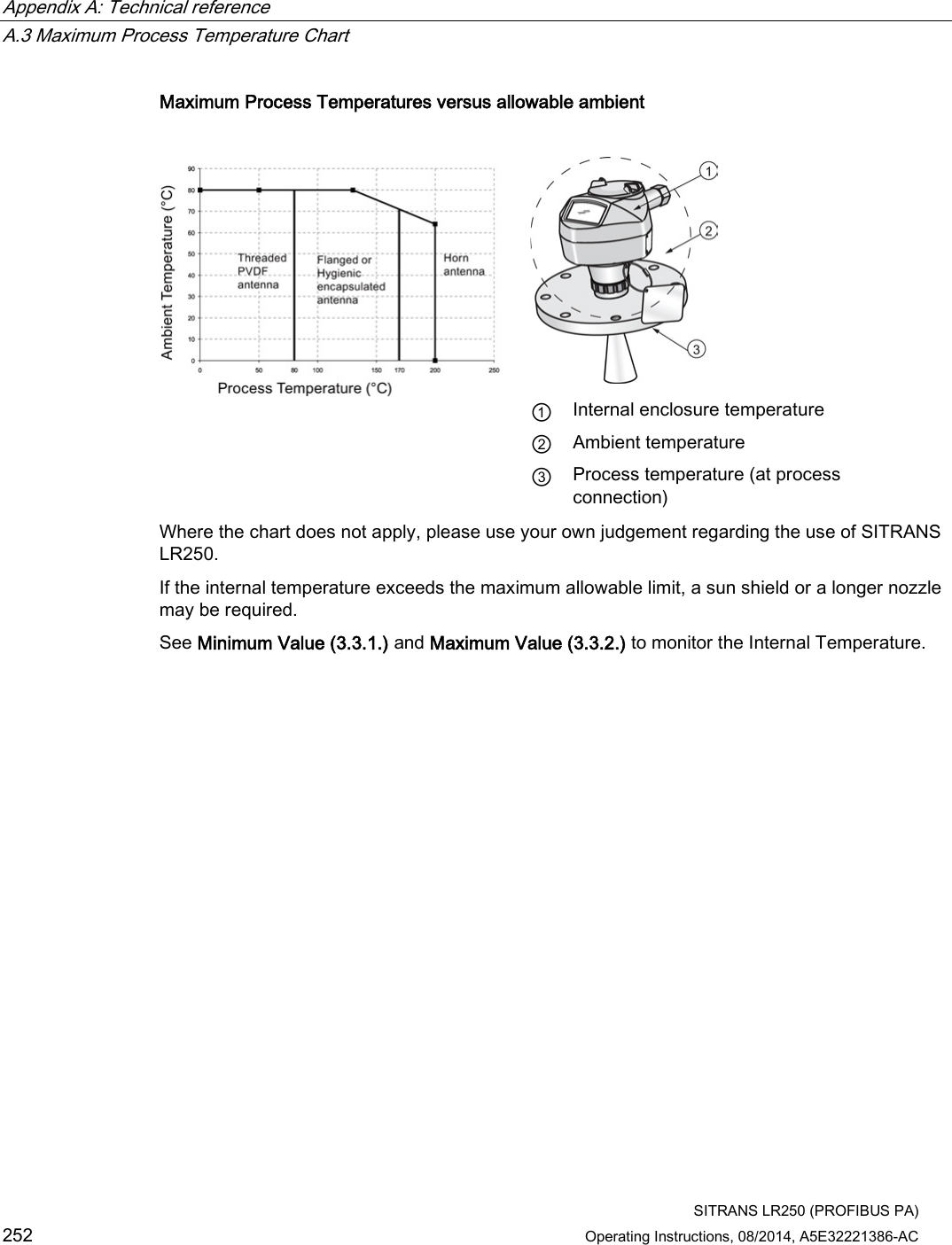
![Technical data 11.2 Performance SITRANS LR250 (PROFIBUS PA) 188 Operating Instructions, 08/2014, A5E32221386-AC Measurement Accuracy (measured in accordance with IEC 60770-1) Maximum measured error =3 mm (0.12")1) 2) 3) including hysteresis and non-repeatability Frequency K-band Maximum measurement range4) 1.5" antenna 10 m (32.8 ft)5) 2" threaded PVDF antenna 2"/DN50/50A Flanged encapsulated antenna (FEA) 2", ISO 2852, DN50 DIN11864-1/2/3, DN50 DIN11851,Tuchenhagen Types F and N Hygienic encapsulated antenna (HEA) all other versions 20 m (65.6 ft) Minimum detectable distance 50 mm (2") from end of antenna6) Update time7) minimum 1 second, depending on settings for Response Rate (2.3.8.1.) and LCD Fast Mode (4.9.). Influence of ambient temperature < 0.003% / K (average over full temperature range, referenced to maximum range) Dielectric constant of material measured dK > 1.6 [antenna and application dependent8)] Memory non-volatile EEPROM no battery required 1) The statistical accuracy is typically 3 mm (0.12") 90% of the time, when tested in accordance with IEC 60770-1. 2) Under severe EMI/EMC environments per IEC 61326-1 or NAMUR NE21, the device error may increase to a maximum of 10 mm (0.4"). 3) For 2" threaded PVDF antenna, Flanged encapsulated antennas and Hygienic encapsulated antennas, the maximum measured error <500 mm from the sensor reference point =25 mm (1"). 4) From sensor reference point: see Dimension drawings (Page 195) and Flanged Horn with extension (Page 202). 5) 20 m (65.6 ft) possible in a stillpipe/bypass 6) Minimum range is antenna length +50 mm (2"). See Dimension drawings (Page 195). 7) Reference conditions: Response Rate (2.4.1.) set to FAST, LCD Fast Mode (4.9.) set to ON. 8) For 1.5" (40 mm) antenna and 2" (50 mm) threaded PVDF antenna, 2"/DN50/50A flanged encapsulated antenna, and 2" ISO 2852, DN50 DIN 11864-1/2/3, DN50 DIN11851, Tuchenhagen Types F and N hygienic encapsulated antenna the minimum dK is limited to 3 unless a stillpipe is used. See Flanged horn antenna (Page 200). See Flanged encapsulated antenna (3"/DN80/80A sizes and larger) (Page 206). See Hygienic encapsulated antenna (2" ISO 2852 sanitary clamp) (Page 208).](https://usermanual.wiki/Siemens-Canada-Siemens-Milltronics-Process-Instruments/LR250.User-Manual-6/User-Guide-2277921-Page-16.png)
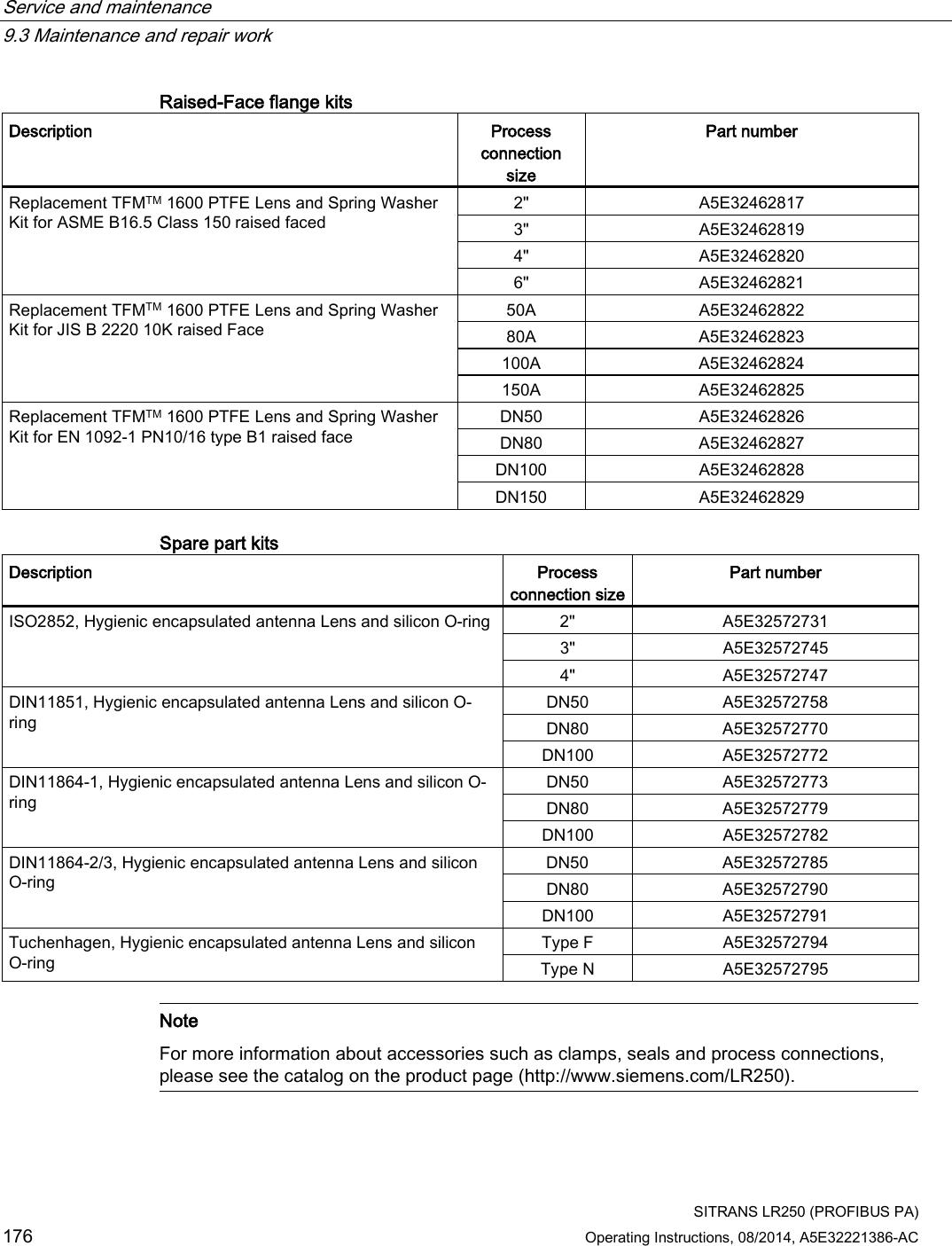
![Technical data 11.3 Interface SITRANS LR250 (PROFIBUS PA) Operating Instructions, 08/2014, A5E32221386-AC 189 11.3 Interface Communication PROFIBUS PA Configuration Remote Siemens SIMATIC PDM Local Siemens infrared handheld programmer Display (local)1) graphic LCD, with bar graph representing level 1) Display quality will be degraded in temperatures below –25 °C (–13 °F) and above +65 °C (+149 °F). 11.4 Mechanical Process connection: Threaded connection 1.5" NPT (ASME B1.20.1), R (BSPT, EN 10226-1) a) or G (BSPP, EN ISO 228-1) or 2" NPT (ASME B1.20.1), R (BSPT, EN 10226-1) or G (BSPP, EN ISO 228-1) or 3" NPT (ASME B1.20.1), R (BSPT, EN 10226-1) or G (BSPP, EN ISO 228-1) Flange connection (flat-face) Materials 2, 3, 4" (ASME 150 lb, 300 lb) DN50, DN80, DN100 (PN 10/16, PN 25/40) 50A, 80A, 100A (JIS 10K) 316L /1.4404 or 316L /1.4435 stainless steel Flange connection (raised face) Materials DN50, DN80, DN100, DN150 (PN 10/16, PN 25/40) 1.4404 or 1.4435 stainless steel, optional Alloy N06022/2.4602 (Hastelloy®C-22 or equivalent) Flanged encapsulated antenna (FEA) connection (raised face) Materials 2, 3, 4, 6" (ASME 150 lb); DN50, DN80, DN100, DN150 (PN10/16); 50A, 80A, 100A, 150A (JIS 10K) 316L /1.4404 or 316L /1.4435 stainless steel Hygienic encapsulated antenna (HEA) connection Materials ISO 2852 (2, 3, 4") DIN 11851 (DN50, DN80, DN100) DIN 11864-1/2/3 (DN50, DN80, DN100) Tuchenhagen (Type F [50 mm] and Type N [68 mm]) 316L /1.4404 or 316L /1.4435 stainless steel ISO 2852 (2, 3, 4") DIN 11864-3 (DN50, DN80, DN100) clamp: 304/1.4301 stainless steel](https://usermanual.wiki/Siemens-Canada-Siemens-Milltronics-Process-Instruments/LR250.User-Manual-6/User-Guide-2277921-Page-17.png)
![Technical data 11.4 Mechanical SITRANS LR250 (PROFIBUS PA) 190 Operating Instructions, 08/2014, A5E32221386-AC Tuchenhagen (Type F [50 mm] and Type N [68 mm]) 316L /1.4404 or 316L/1.4435 stainless steel clamp: 304/1.4301 stainless steel nut connection: 303/1.4305 stainless steel DIN 11851/11864-1 (DN50, DN80, DN100) captive slotted nut connection: 304L/1.4307 DIN 11864-2 (DN50, DN80, DN100) mounting nuts and bolts: 304/1.4301 stainless steel Antenna: Horn Materials standard 1.5" (40 mm), 2" (50 mm), 3" (80 mm), and 4" (100 mm) horn, optional 100 mm (4") horn extension 316L stainless steel with PTFE emitter optional Alloy N06022/2.4602 (Hastelloy®C-22 or equivalent) with PTFE emitter Threaded PVDF antenna Wetted materials 2" (50 mm) PVDF (Polyvinylidene fluoride) Flanged encapsulated antenna Wetted materials 316L /1.4404 or 316L /1.4435 stainless steel TFMTM 1600 PTFE lens Hygienic encapsulated antenna Wetted material 316L/1.4404 or 316L/1.4435 stainless steel TFMTM 1600 PTFE (plus chosen seal) Enclosure Construction aluminum, polyester powder-coated Conduit entry 2 x M20x1.5, or 2 x ½" NPT Ingress protection Type 4X/NEMA 4X, Type 6/NEMA 6, IP67, IP68 Weight (excluding extensions): 1.5" threaded connection with 1.5" horn antenna approximately 5.1kg (11.2 lb) 2" threaded connection with 2" horn antenna approximately 5.5 kg (12.1 lb) 3" threaded connection with 3" horn antenna approximately 7.0 kg (15.4 lb) 2" threaded PVDF antenna approximately 3.3 kg (7.27 lb) DN50 PN 10/16 or 2" 150 lb flat-face flange with 2" horn antenna approximately 8 kg (17.6 lb) DN100 PN 25/40 or 4" ASME 300 lb flat-face flange with 4" horn antenna approximately 17.4 kg (38.3 lb) DN50 PN 10/16 raised-face flange with 2" horn antenna approximately 6 kg (13.2 lb) DN100 PN 25/40 raised-face flange with 4" horn antenna approximately 11.3 kg (24.9 lb)](https://usermanual.wiki/Siemens-Canada-Siemens-Milltronics-Process-Instruments/LR250.User-Manual-6/User-Guide-2277921-Page-18.png)
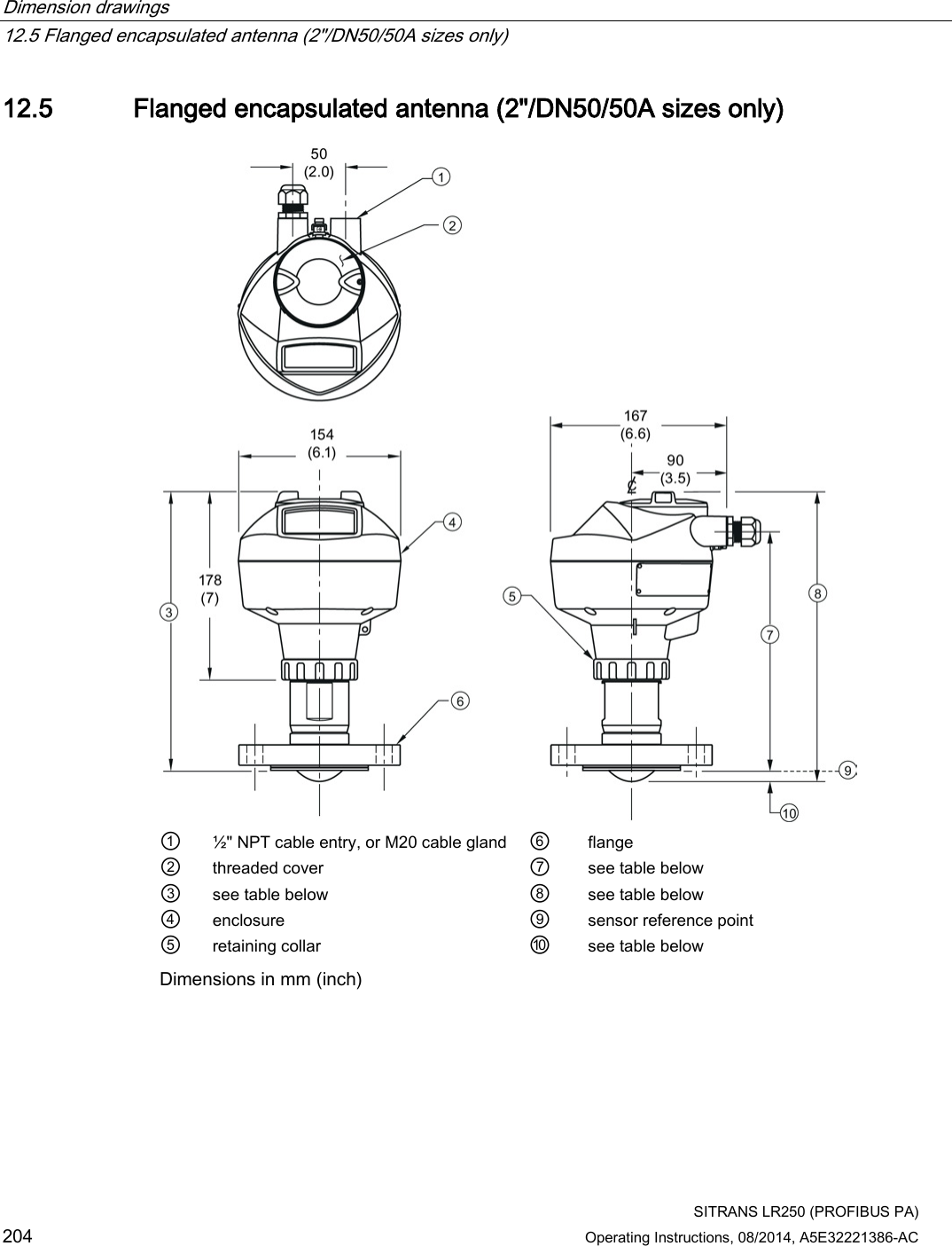
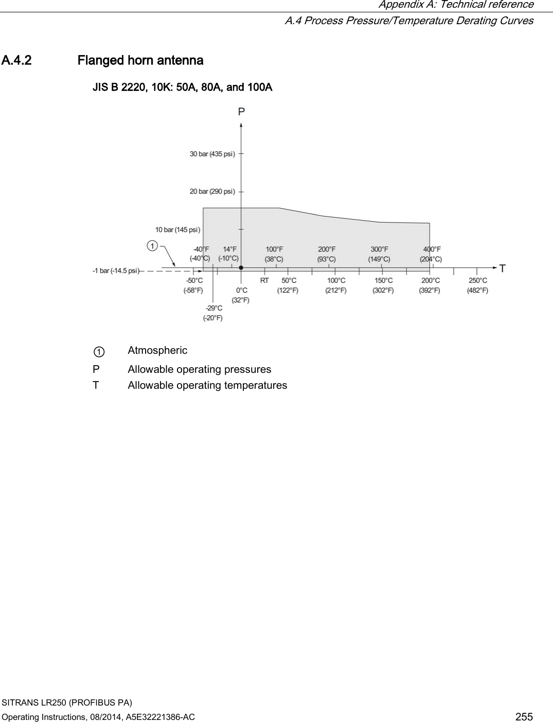
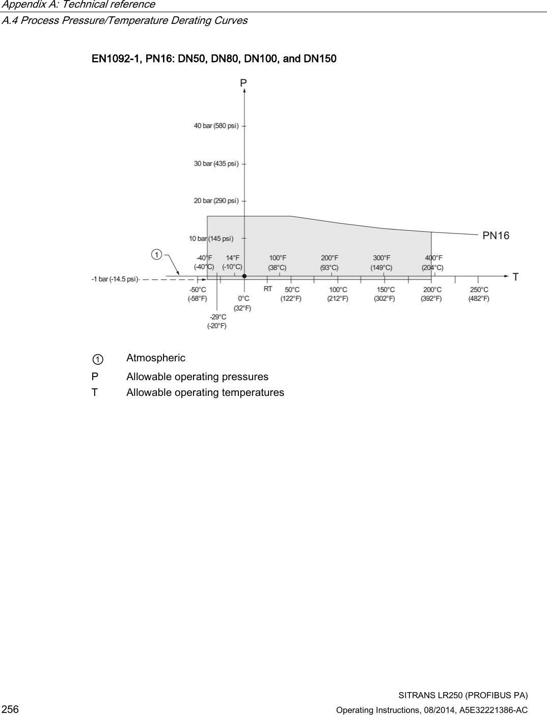
![Dimension drawings 12.5 Flanged encapsulated antenna (2"/DN50/50A sizes only) SITRANS LR250 (PROFIBUS PA) Operating Instructions, 08/2014, A5E32221386-AC 205 Flanged encapsulated antenna (2"/DN50/50A) dimensions Flange size ③ mm (inch) ⑦ mm (inch) ⑧ mm (inch) ⑩ mm (inch)1) 2"/DN50/50A 263 (10.35) 223 (8.78) 274 (10.79) 11 (0.43) 1) Height from tip of lens to sensor reference point as shown. Flange size Flange class Flange O.D. [mm (inch)] Antenna aperture size [mm (inch)] Beam angle (°)1) Measurement range [m (ft)] 2" 150 LB 152 (5.98) 50 (1.97) 12.8 10 (32.8)2) DN50 PN10/16 165 (6.50) 50A 10K 155 (6.10) 1) -3 dB in the direction of the polarization axis. 2) 20m if installed in stillpipe See Raised-Face Flange per EN 1092-1, (Page 230)and Polarization reference point (Page 31).](https://usermanual.wiki/Siemens-Canada-Siemens-Milltronics-Process-Instruments/LR250.User-Manual-6/User-Guide-2277921-Page-33.png)
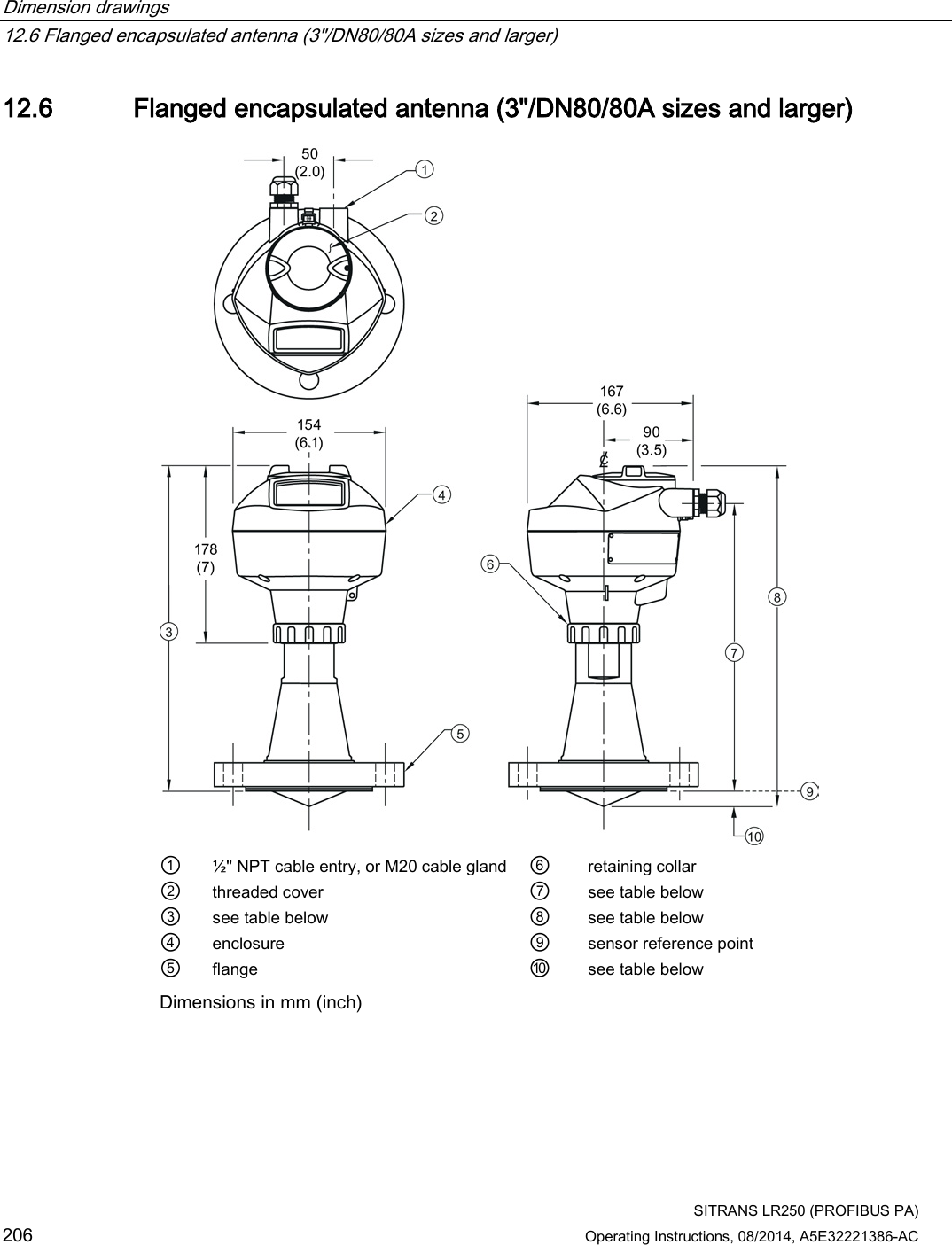
![Dimension drawings 12.6 Flanged encapsulated antenna (3"/DN80/80A sizes and larger) SITRANS LR250 (PROFIBUS PA) Operating Instructions, 08/2014, A5E32221386-AC 207 Flanged encapsulated antenna (3"/DN80/80A and larger) dimensions Flange size ③ mm (inch) ⑦ mm (inch) ⑧ mm (inch) ⑩ mm (inch)1) 3"/DN80/80A 328 (12.91) 288 (11.34) 343 (13.50) 15 (0.59) 4"/DN100/100A 328 (12.91) 288 (11.34) 343 (13.50) 13 (0.51) 6"/DN150/150A 333 (13.11) 293 (11.54) 348 (13.70) 15 (0.59) 1) Height from tip of lens to sensor reference point as shown. See also Raised-Face Flange per EN 1092-1. Flange size Flange class Flange O.D. [mm (inch)] Antenna aperture size [mm (inch)] Beam angle (°)1) Measurement range [m (ft)] 3" 150 LB 190 (7.48) 75 (2.95) 9.6 20 (65.6) DN80 PN10/16 200 (7.87) 80A 10K 185 (7.28) 4" 150 LB 230 (9.06) 75 (2.95) 9.6 20 (65.6) DN100 PN10/16 220 (8.66) 100A 10K 210 (8.27) 6" 150 LB 280 (11.02) 75 (2.95) 9.6 20 (65.6) DN150 PN10/16 285 (11.22) 150A 10K 280 (11.02) 1) -3 dB in the direction of the polarization axis. See Raised-Face Flange per EN 1092-1 (Page 230), and Polarization reference point (Page 31).](https://usermanual.wiki/Siemens-Canada-Siemens-Milltronics-Process-Instruments/LR250.User-Manual-6/User-Guide-2277921-Page-35.png)

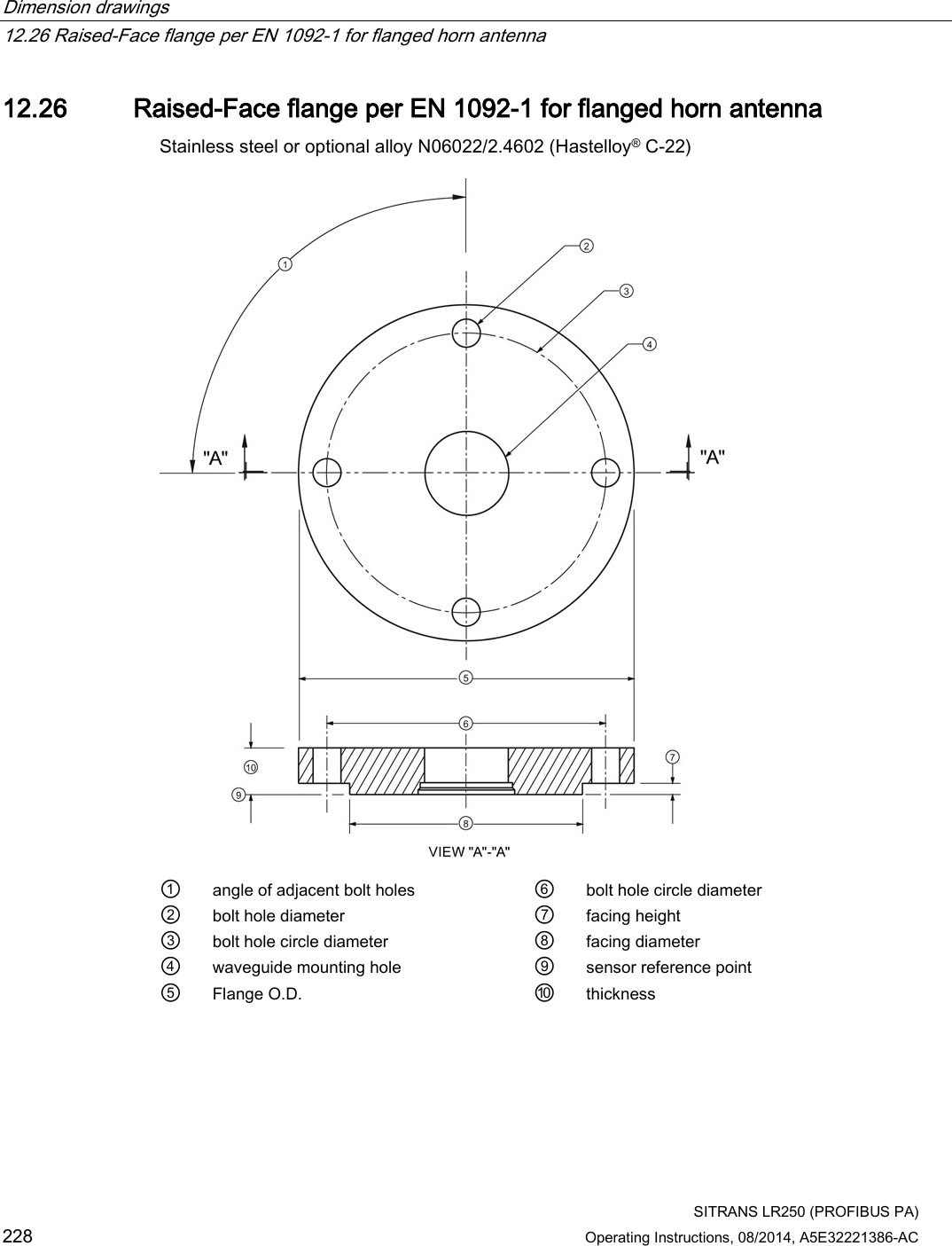
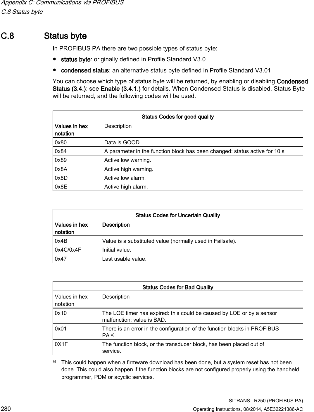
![Dimension drawings 12.26 Raised-Face flange per EN 1092-1 for flanged horn antenna SITRANS LR250 (PROFIBUS PA) Operating Instructions, 08/2014, A5E32221386-AC 229 Raised-Face flange dimensions Pipe size Flange bolt hole pattern ⑤ Flange O.D. (mm) ③ Bolt hole circle Ø (mm) ② Bolt hole Ø (mm) No. of bolts ① Angle of adjacent bolt holes ⑧ Facing Ø (mm) ⑩ Thickness (mm) DN50 PN10/PN16 165 125 18 4 90 102 18 DN80 PN10/PN16 200 160 18 8 45 138 20 DN100 PN10/PN16 220 180 18 8 45 158 20 DN150 PN10/PN16 285 240 22 8 45 212 22 DN50 PN25/PN40 165 160 18 4 90 138 20 DN80 PN25/PN40 200 160 18 8 45 138 24 DN100 PN25/PN40 235 190 22 8 45 162 24 DN150 PN25/PN40 300 250 26 8 45 218 28 Raised-Face flange markings Blind Flange Markings (Optional Manufacturer’s Logo [optional]; Flange Standard; Nominal Size; Material; Heat Code) Machining Identification Welded Assembly Identification a) Serial no. Logo Flange series Flange series Heat Code no. Facing Manufacturer’s logo; EN 1092-1 05 ‘B1’; ‘DN50’ ‘PN16’ ‘1.4404 or 1.4435’ A1B2C3 mmddyyxxx xxxxx xxxxx A1B2C3 RF a) When flange material is alloy N06022/2.4602, additional material and heat code identification is provided. The flange markings are located around the outside edge of the flange. Serial number: a unique number allotted to each flange, including the date of manufacture (MMDDYY) followed by a number from 001 to 999 (indicating the sequential unit produced). Flange series: the Siemens Milltronics drawing identification. Heat code: a flange material batch code identification.](https://usermanual.wiki/Siemens-Canada-Siemens-Milltronics-Process-Instruments/LR250.User-Manual-6/User-Guide-2277921-Page-57.png)
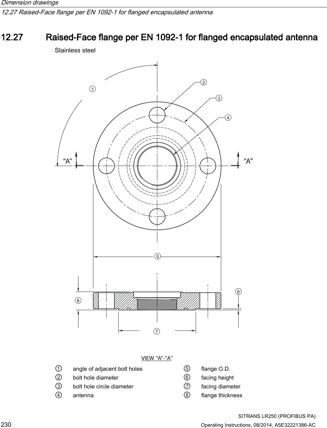
![Dimension drawings 12.27 Raised-Face flange per EN 1092-1 for flanged encapsulated antenna SITRANS LR250 (PROFIBUS PA) Operating Instructions, 08/2014, A5E32221386-AC 231 Raised-Face flange dimensions Pipe size Flange class ⑤ Flange O.D. [mm (inch)] ③ Bolt hole circle Ø [mm (inch)] ② Bolt hole Ø [mm (inch)] No. of bolt holes ① Angle of adjacent bolt holes ⑦ Facing Ø [mm (inch)] ⑨ Flange thickness [mm (inch)] ⑥ Flange facing thickness [mm (inch)] 2" 150 LB 152 (5.98) 120.7 (4.75) 19 (0.75) 4 90 92.1 (3.63) 20.6 (0.81) 1.5 (0.06) 3" 190 (7.48) 152.4 (6.00) 127 (5.00) 25.9 (1.02) 2 (0.08) 4" 230 (9.06) 190.5 (7.50) 8 45 157.2 (6.19) 2 (0.08) 6" 280 (11.02) 241.3 (9.50) 22.2 (0.87) 215.9 (8.50) 26.9 (1.06) 1.5 (0.06) DN50 PN10/16 155 (6.10) 125 (4.92) 18 (0.71) 4 90 102 (4.02) 18 (0.71) 2 (0.08) DN80 200 (7.87) 160 (6.30) 8 45 138 (5.43) 20 (0.79) 2 (0.08) DN100 220 (8.66) 180 (7.09) 158 (6.22) 2 (0.08) DN150 285 (11.22) 240 (9.45) 22 (0.87) 212 (8.35) 22 (0.87) 2 (0.08) 50A 10K 155 (6.10) 120 (4.72) 19 (0.75) 4 90 96 (3.78) 16 (0.63) 2 (0.08) 80A 185 (7.28) 150 (5.91) 8 45 126 (4.96) 18 (0.71) 2 (0.08) 100A 210 (8.27) 175 (6.89) 151 (5.94) 2 (0.08) 150A 280 (11.02) 240 (9.45) 23 (0.91) 212 (8.35) 22 (0.87) 2 (0.08)](https://usermanual.wiki/Siemens-Canada-Siemens-Milltronics-Process-Instruments/LR250.User-Manual-6/User-Guide-2277921-Page-59.png)
![Dimension drawings 12.27 Raised-Face flange per EN 1092-1 for flanged encapsulated antenna SITRANS LR250 (PROFIBUS PA) 232 Operating Instructions, 08/2014, A5E32221386-AC Raised-Face flange markings Blind Flange Markings (Optional Manufacturer’s Logo [optional]; Flange Standard; Nominal Size; Material; Heat Code) Machining Identification Welded Assembly Identification Serial no. Logo Flange series Flange series Heat Code no. Facing Manufacturer’s logo; EN 1092-1 05 ‘B1’; ‘DN50’ ‘PN16’ ‘1.4404 or 1.4435’ A1B2C3 mmddyyxxx xxxxx xxxxx A1B2C3 RF The flange markings are located around the outside edge of the flange. Serial number: a unique number allotted to each flange, including the date of manufacture (MMDDYY) followed by a number from 001 to 999 (indicating the sequential unit produced). Flange series: the Siemens Milltronics drawing identification. Heat code: a flange material batch code identification.](https://usermanual.wiki/Siemens-Canada-Siemens-Milltronics-Process-Instruments/LR250.User-Manual-6/User-Guide-2277921-Page-60.png)

![SITRANS LR250 (PROFIBUS PA) Operating Instructions, 08/2014, A5E32221386-AC 241 Appendix A: Technical reference A Note Where a number follows the parameter name [for example, Master Reset (4.1.)] this is the parameter access number via the handheld programmer. See Parameter Reference (Page 107) for a complete list of parameters. A.1 Principles of operation SITRANS LR250 is a 2-wire 25 GHz pulse radar level transmitter for continuous monitoring of liquids and slurries. (The microwave output level is significantly less than that emitted from cellular phones.) Radar level measurement uses the time of flight principle to determine distance to a material surface. The device transmits a signal and waits for the return echo. The transit time is directly proportional to the distance from the material. Pulse radar uses polarized electromagnetic waves. Microwave pulses are emitted from the antenna at a fixed repetition rate, and reflect off the interface between two materials with different dielectric constants (the atmosphere and the material being monitored). Electromagnetic wave propagation is virtually unaffected by temperature or pressure changes, or by changes in the vapor levels inside a vessel. Electromagnetic waves are not attenuated by dust. SITRANS LR250 consists of an enclosed electronic circuit coupled to an antenna and process connection. The electronic circuit generates a radar signal (25 GHz) that is directed to the antenna. The signal is emitted from the antenna, and the reflected echoes are digitally converted to an echo profile. The profile is analyzed to determine the distance from the material surface to the sensor reference point. See Dimension drawings (Page 195). This distance is used as a basis for the display of material level and mA output.](https://usermanual.wiki/Siemens-Canada-Siemens-Milltronics-Process-Instruments/LR250.User-Manual-6/User-Guide-2277921-Page-69.png)
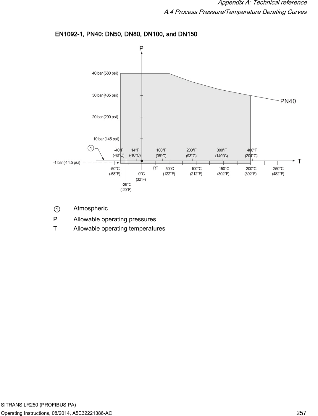
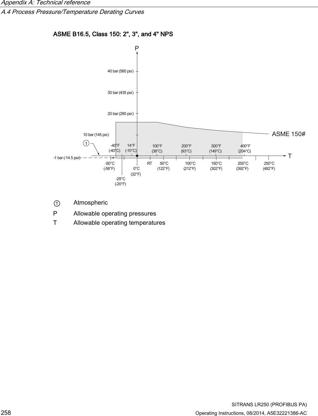
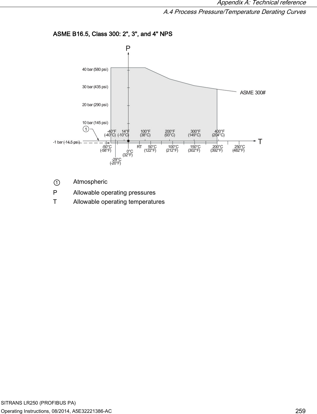
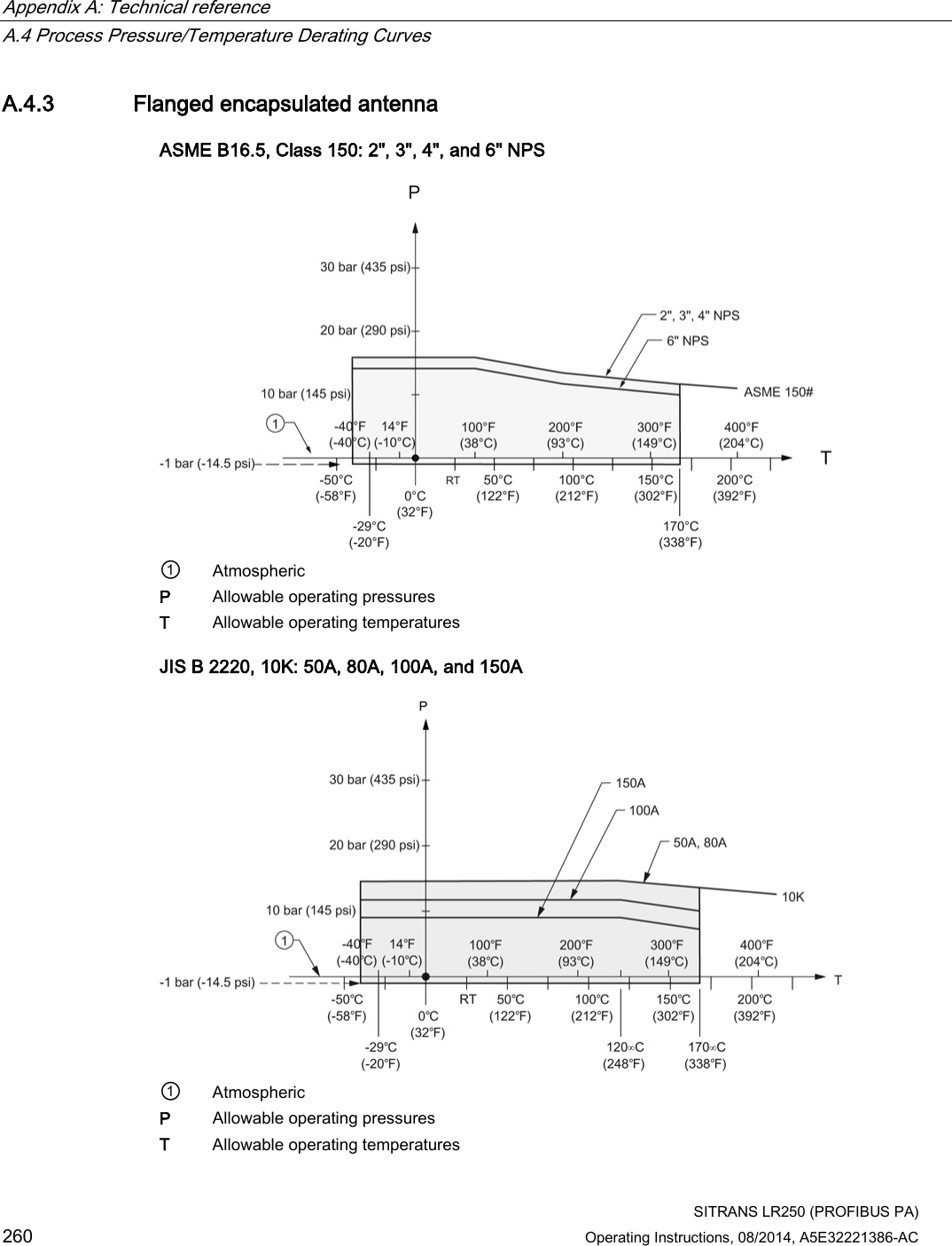
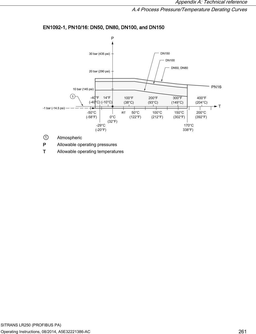
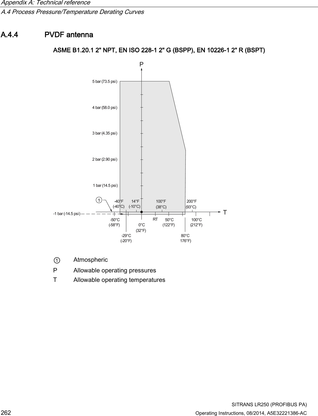
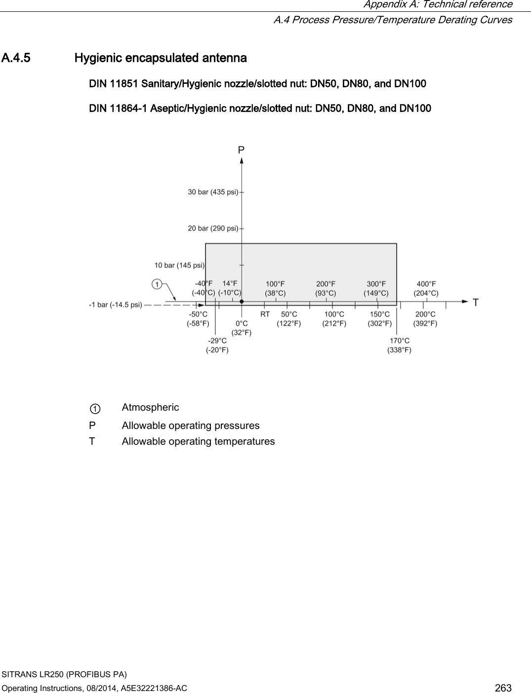
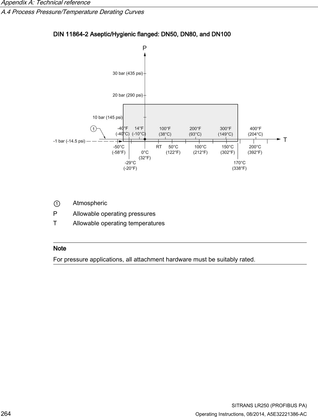
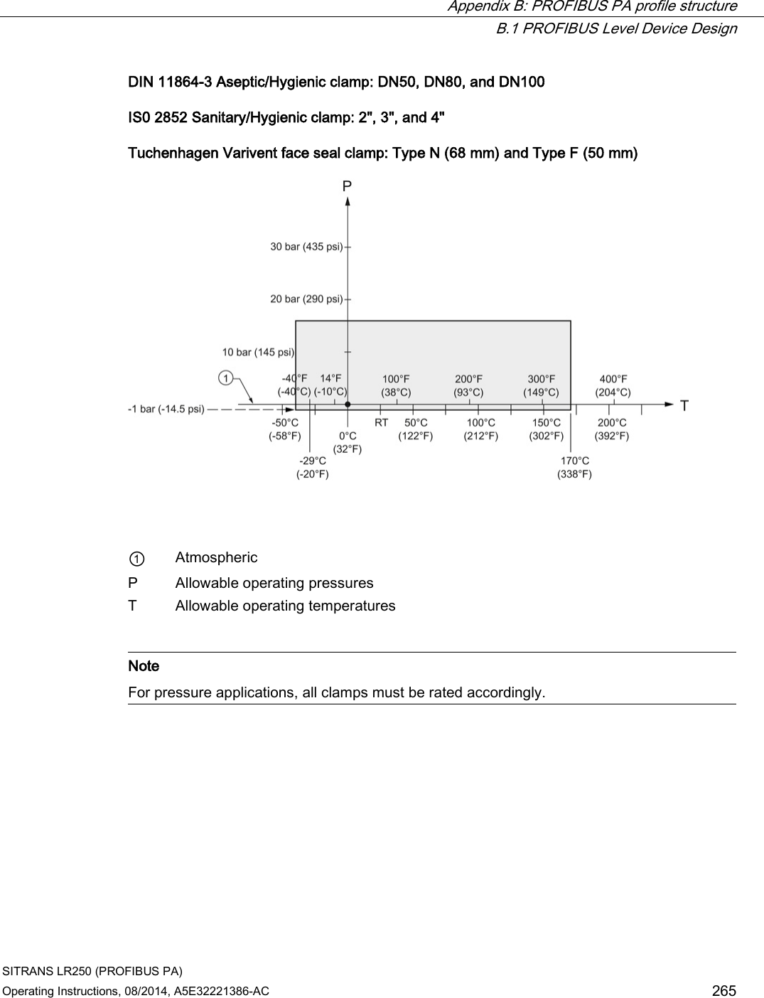
![Appendix A: Technical reference A.4 Process Pressure/Temperature Derating Curves SITRANS LR250 (PROFIBUS PA) 254 Operating Instructions, 08/2014, A5E32221386-AC A.4.1 Horn antenna 1.5", 2" and 3" [NPT, G (BSPP), R (BSPT)] Threaded Versions ① Atmospheric P Allowable operating pressures T Allowable operating temperatures](https://usermanual.wiki/Siemens-Canada-Siemens-Milltronics-Process-Instruments/LR250.User-Manual-6/User-Guide-2277921-Page-82.png)
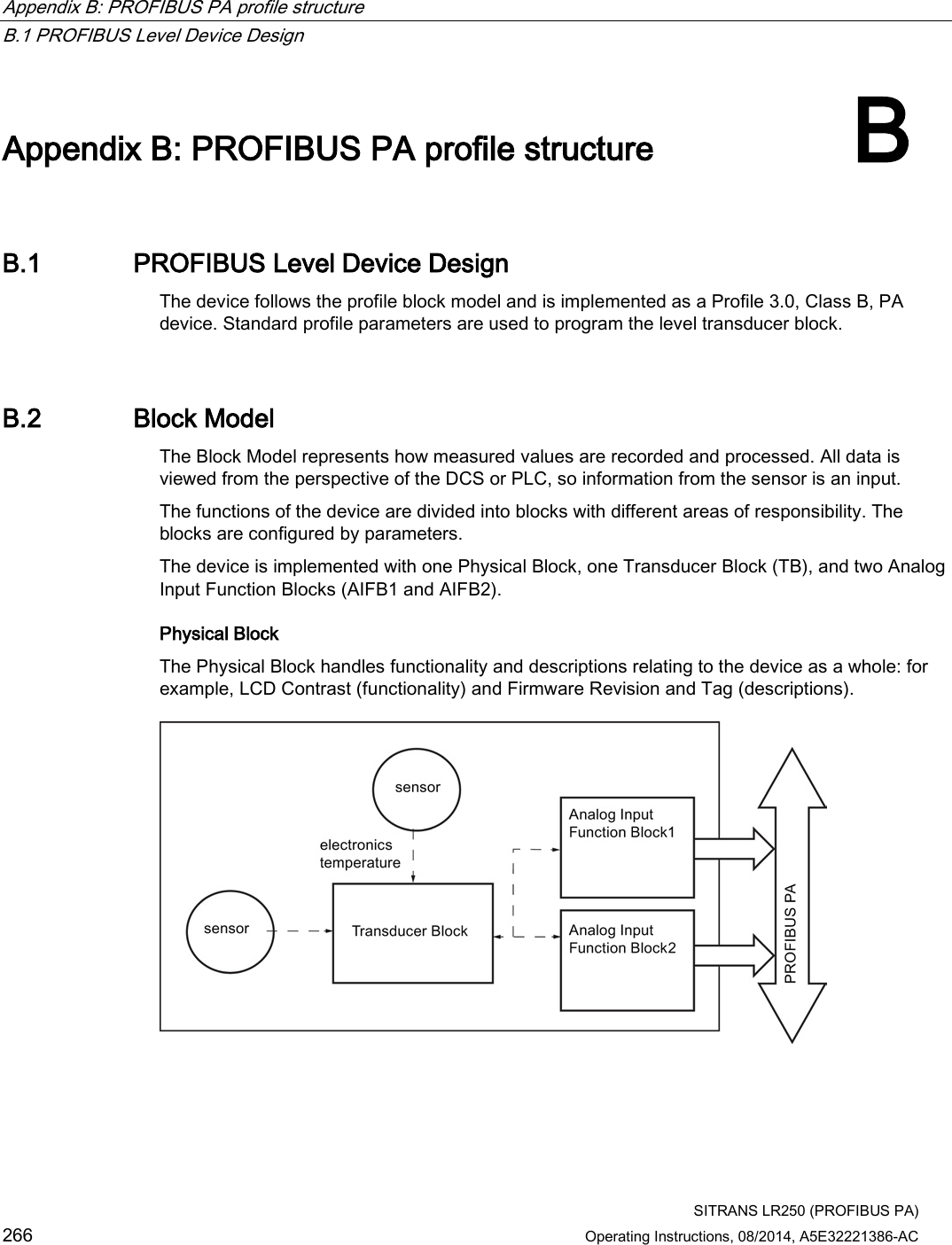
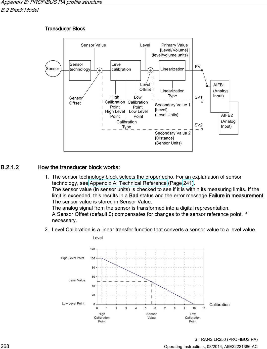
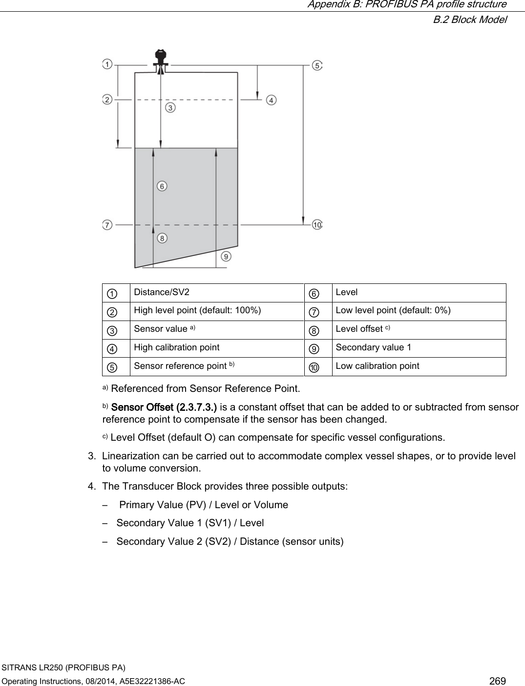
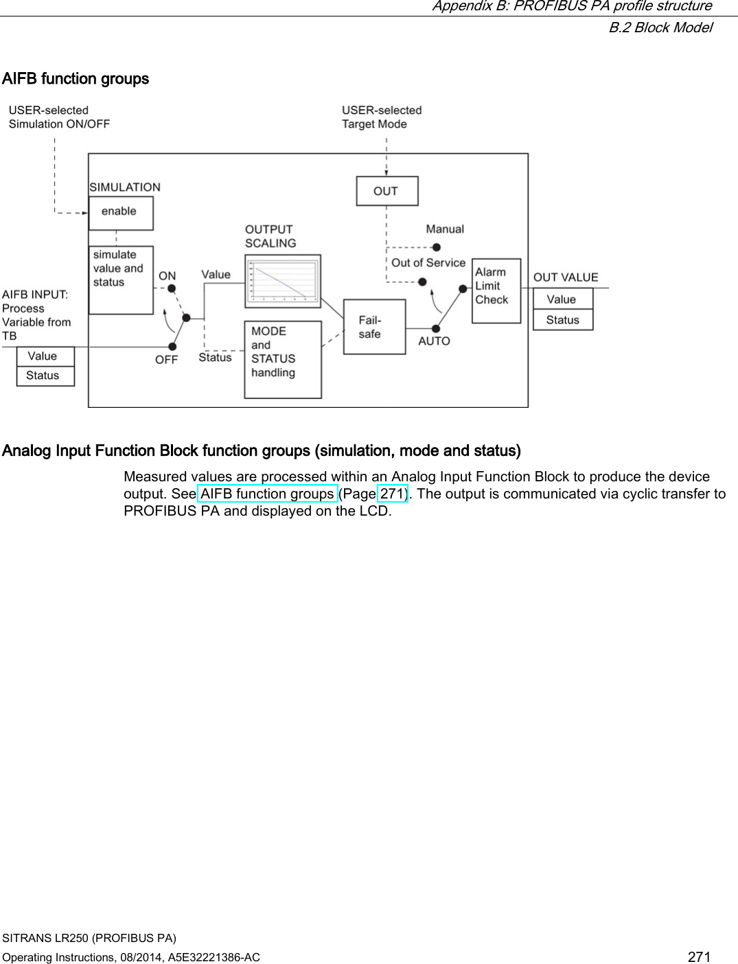
![Appendix B: PROFIBUS PA profile structure B.2 Block Model SITRANS LR250 (PROFIBUS PA) Operating Instructions, 08/2014, A5E32221386-AC 267 Transducer Block (TB) The Transducer Block carries out adjustments to the sensor, such as level calibration and volume calibration. It supplies the measurement value [Primary Value (PV), Secondary Value 1 (SV1), or Secondary Value 2 (SV2)] utilized by either or both of the AIFBs. Analog Input Function Blocks AIFB1 and AIFB2 The two AIFBs are completely independent of each other. They utilize the measurement value output from the Transducer Block [Primary Value (PV), Secondary Value 1 (SV1), or Secondary Value 2 (SV2)] and apply any required quality checks, scaling, and Fail-safe operation selections. The Analog Input Function Block output supplies the measured value and associated status information to the PROFIBUS PA network via cyclic data transfer. B.2.1 Description of the blocks B.2.1.1 Transducer Block function groups The figure below shows the signal flow of measured values from the sensor through the Transducer Block into the output value: ● Primary Value (PV): Level or Volume ● Secondary Value 1 (SV1): Level ● Secondary Value 2 (SV2): Distance The Transducer Block implements all of the basic parameters (see diagram below), including level to volume calculation, if that option has been selected.](https://usermanual.wiki/Siemens-Canada-Siemens-Milltronics-Process-Instruments/LR250.User-Manual-6/User-Guide-2277921-Page-95.png)

![Appendix C: Communications via PROFIBUS C.6 Operating as a profile device SITRANS LR250 (PROFIBUS PA) Operating Instructions, 08/2014, A5E32221386-AC 277 1. Navigate to Service (4.) > Master Reset (4.1.). (You can enter the numeric value instead of navigating via the Arrow keys.) 2. Press RIGHT Arrow to open Edit Mode then scroll down to DEV ADDRESS and press RIGHT Arrow to select it. The address will be reset to 126, and if the address lock was on, it will be disabled. 3. Press LEFT Arrow to exit. C.6 Operating as a profile device Every manufactured PROFIBUS product has a unique PROFIBUS identification number which identifies it to the system. PROFIBUS Profile Standard version 3.01 also defines a Profile Model which can identify a product as a generic profile device on the network. SITRANS LR250 can be identified in one of three ways: Device Identification Profile Model STD PROFILE Standard Profile (uses generic GSD for 2 AIFB [ident # = 0x9701] * MANUFACTURER Manufacturer-specific (uses Siemens EDD and GSD file, which identifies the LR250 [PROFIBUS PA]) [ident # = 0x8150] STD – AIFB 1 ONLY Standard Profile AIFB 1 only (uses generic GSD for 1 AIFB) [ident # = 0x9700] Defining the device as Profile-specific as opposed to Manufacturer-specific makes it possible to exchange the device for any other device of the same profile type without changing the GSD file. To set up SITRANS LR250 as a profile device see PROFIBUS Ident Number (5.2.). C.6.1 Configuring a new device See Configuring a new device (Page 77).](https://usermanual.wiki/Siemens-Canada-Siemens-Milltronics-Process-Instruments/LR250.User-Manual-6/User-Guide-2277921-Page-105.png)
![Appendix C: Communications via PROFIBUS C.7 Cyclic versus acyclic data SITRANS LR250 (PROFIBUS PA) Operating Instructions, 08/2014, A5E32221386-AC 279 C.7.1 Cyclic data When you configure SITRANS LR250 on the PROFIBUS PA bus, there are two slots available for modules. Note Each of the slots has to have a module defined in it. Slot 0 always transmits AIFB1 information; slot 1 defaults to Free Place, but can be changed to AIFB2 information. If you do not wish to have data transmitted, then you must use a Free Place module in that slot. Each of the two Analog Input Function Blocks can be set up to return Level, Distance, or Volume. Within the function blocks, the values are scaled according to the user requirements [see Analog Input Function Blocks 1 and 2 (Page 270) for details]. AIFB1 and AIFB2 return 5 bytes of data each: Floating Point Status AIFB1 byte 1 byte 2 byte 3 byte 4 byte 5 AIFB2 byte 6 byte 7 byte 8 byte 9 byte 10 The first 4 bytes are the floating point representation (IEEE) of the variable. The variables are the outputs of the function block. The 5th byte is the status word and the list of possible values is given in the chart below. The 5 bytes must be read consistently, in a contiguous chunk: they cannot be read byte by byte, and cannot suffer an interrupt. If you are using an S7-300 / 400, you will need to use SFC14 DPRD_DAT: Read Consistent Data of a Standard PD Slave.](https://usermanual.wiki/Siemens-Canada-Siemens-Milltronics-Process-Instruments/LR250.User-Manual-6/User-Guide-2277921-Page-107.png)
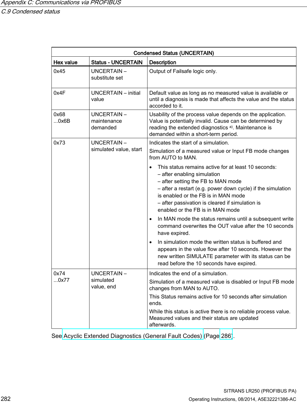
![Appendix C: Communications via PROFIBUS C.10 Diagnostics SITRANS LR250 (PROFIBUS PA) Operating Instructions, 08/2014, A5E32221386-AC 283 Condensed Status (BAD) Hex value Status - BAD Description 0x00 BAD – non specific Proxy determines that a device does not communicate. 0x23 BAD – passivated (diagnostics alerts disabled) Configured failsafe value is used, accompanied by this status. 0x24 ...0x27 BAD – maintenance alarm, more diagnosis available No measurement available because of a failure. 0x25 BAD – process related, no maintenance No measurement available because of invalid process conditions. 0x3C ...0x3F BAD – function check / local override, value not usable Occurs during cleaning or calibration process. C.10 Diagnostics All diagnostic information shown below is viewable via PDM. C.10.1 Diagnosis reply (available cyclically) During DPV0 data exchange, the PROFIBUS PA slave will notify the Master when a serious error occurs. The Master will then send a Diagnosis request. The reply to this request is normally logged in the PLC and is referred to as the "Hex values." The reply may contain two parts. The first part is 6 bytes long and is defined by the PROFIBUS standard. If there is a second part, it is called the ’extended cyclic diagnosis’ and it is 8 bytes long. The last 4 bytes of the extended diagnostic message give the error diagnosis [see Extended Mode Diagnosis (Page 284) and Condensed Mode Diagnosis (Page 285)]. The same information is also available acyclically via the Diagnosis Object.](https://usermanual.wiki/Siemens-Canada-Siemens-Milltronics-Process-Instruments/LR250.User-Manual-6/User-Guide-2277921-Page-111.png)
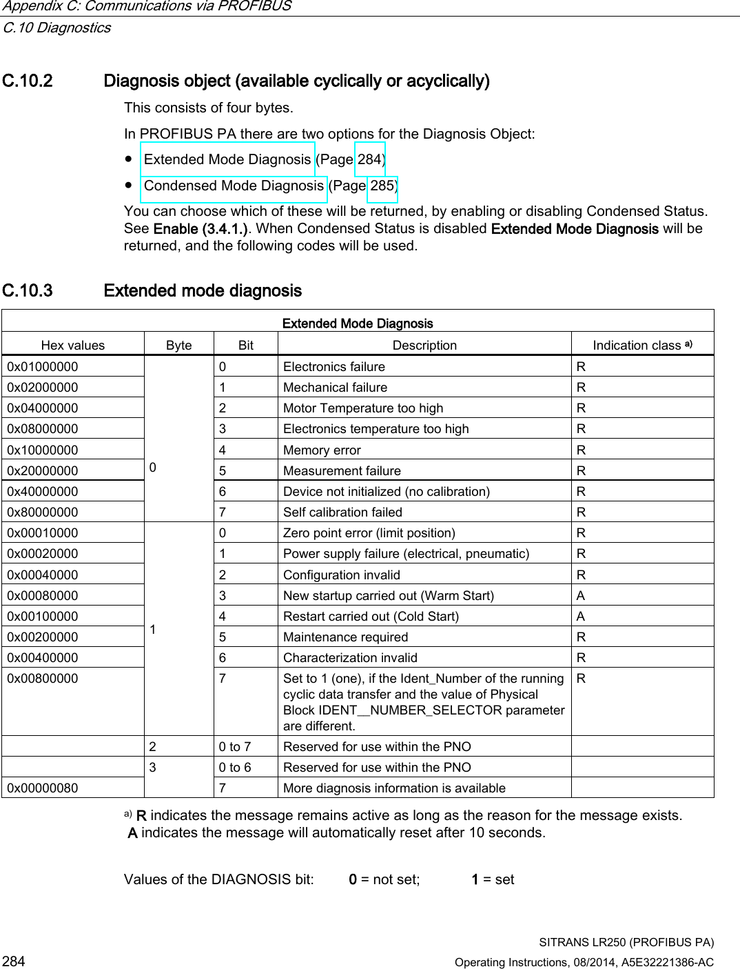
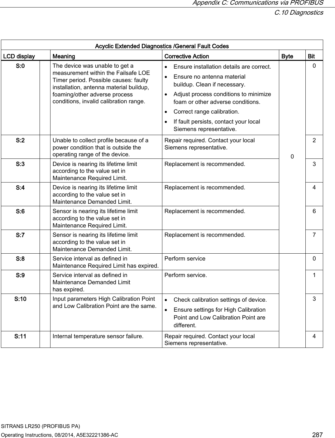
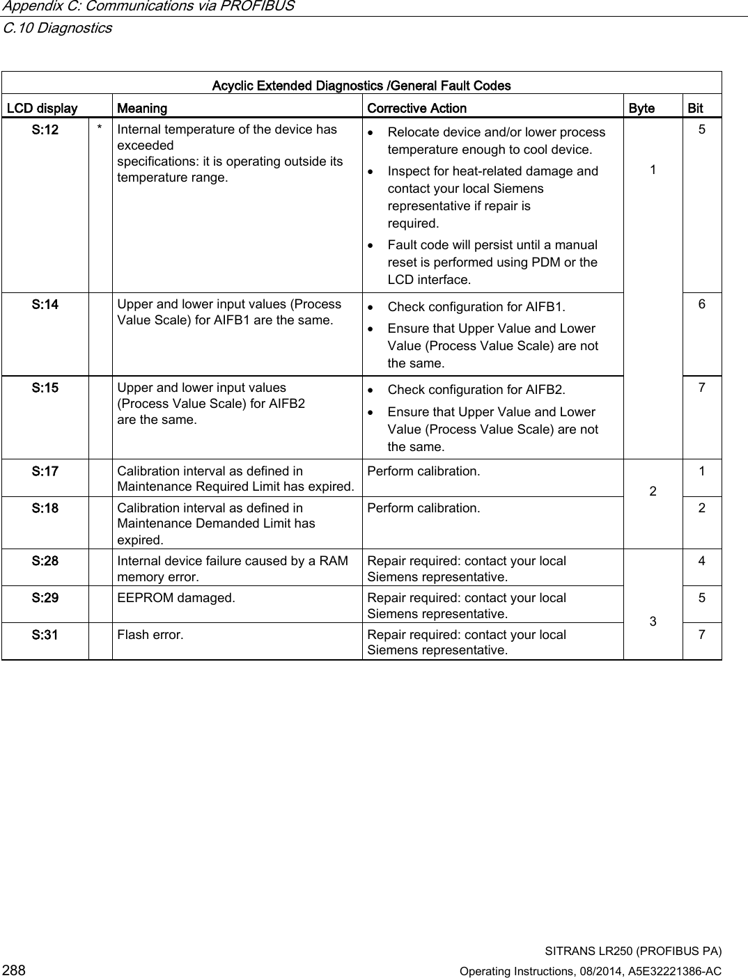
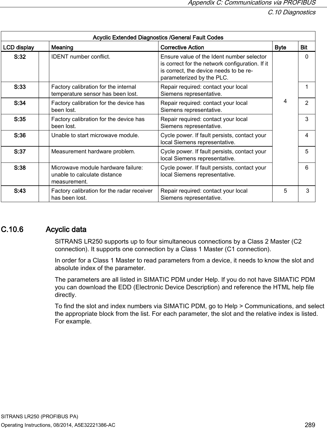
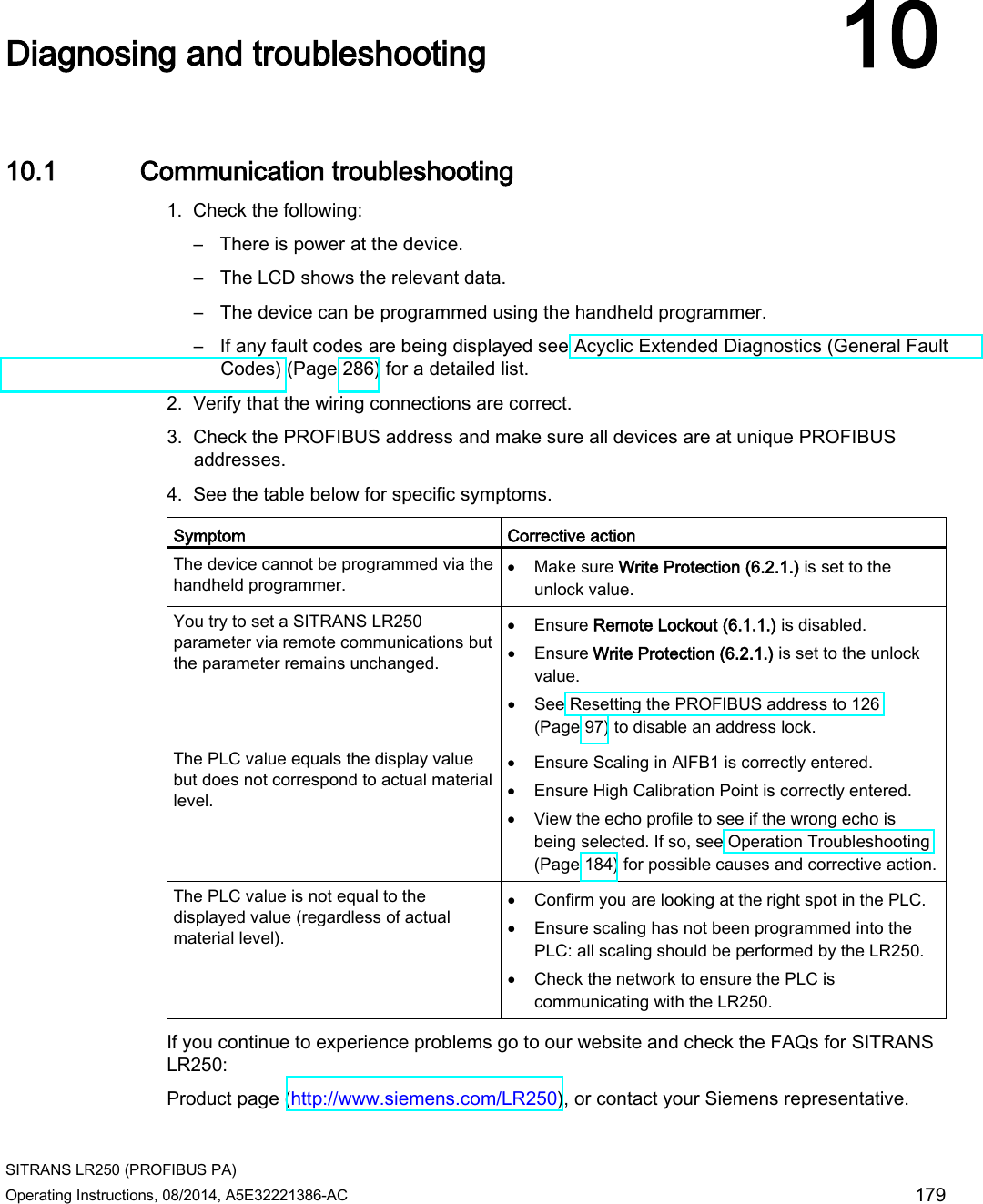
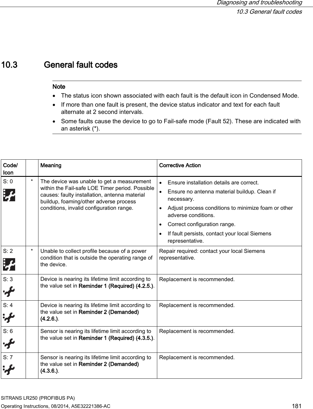
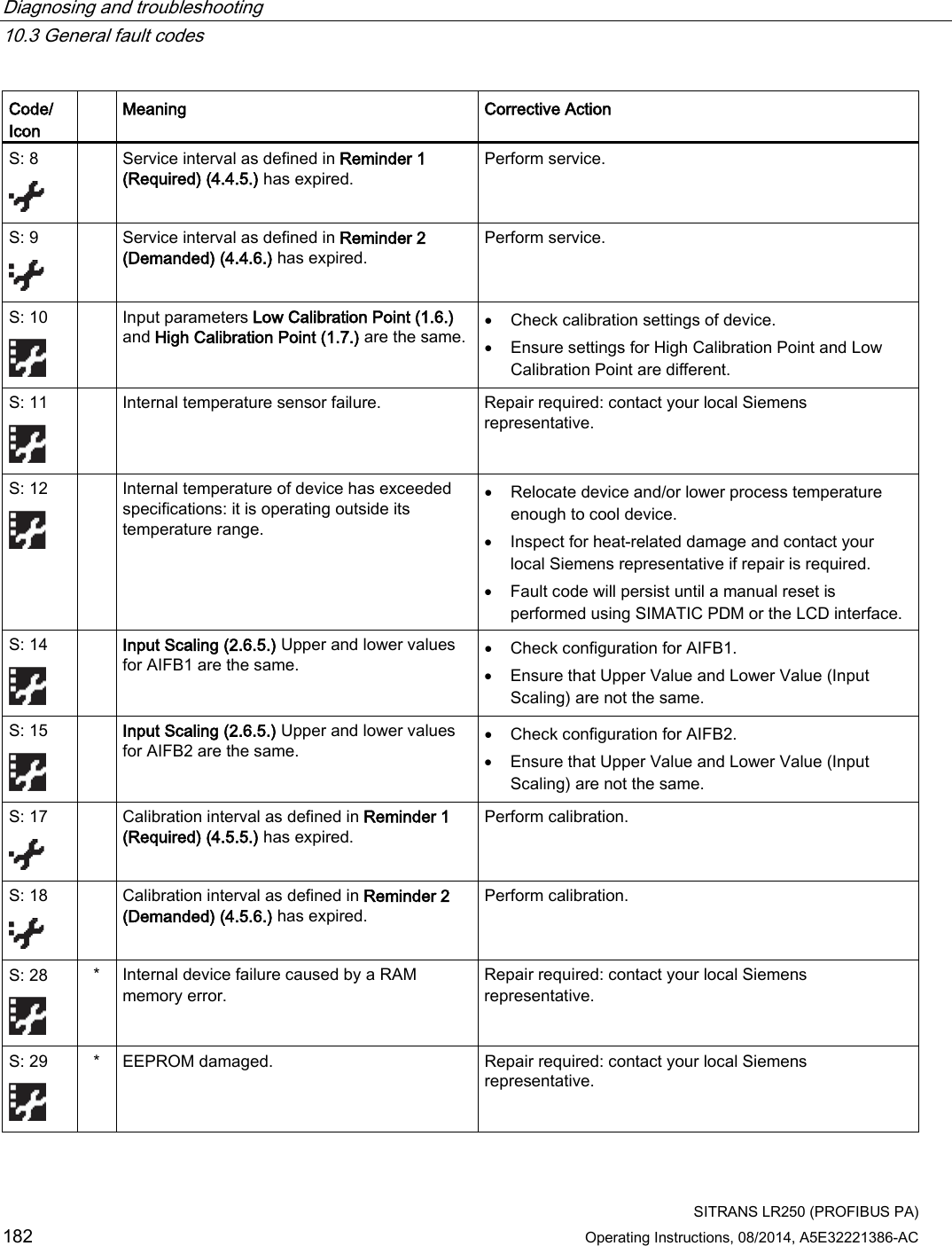
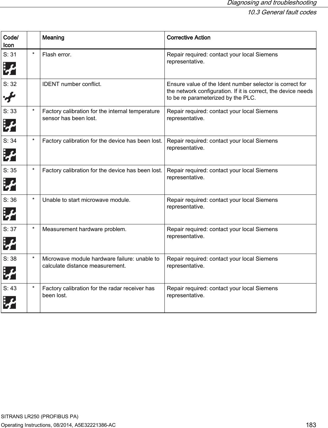
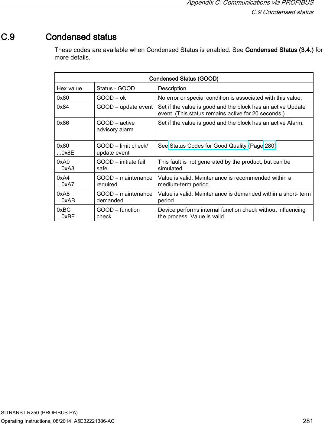
![Appendix C: Communications via PROFIBUS C.10 Diagnostics SITRANS LR250 (PROFIBUS PA) 286 Operating Instructions, 08/2014, A5E32221386-AC C.10.5 Acyclic extended diagnostics (general fault codes) In addition to the extended diagnostics available by cyclic data exchange (shown above), further extended diagnostics are available via acyclic communications. This consists of six bytes. See Diagnosis reply (available cyclically) (Page 283) for information on the location of the Extended Diagnostics. Note Certain fault codes (identified by an asterisk [*] in the table below) will persist until a manual reset has been performed [see Fault Reset (3.2.)].](https://usermanual.wiki/Siemens-Canada-Siemens-Milltronics-Process-Instruments/LR250.User-Manual-6/User-Guide-2277921-Page-114.png)