Siemens Canada Siemens Milltronics Process Instruments LR560 SITRANS LR560 Level Probing Radar User Manual LY01 LR560FF
Siemens Canada Ltd. - Siemens Milltronics Process Instruments SITRANS LR560 Level Probing Radar LY01 LR560FF
Contents
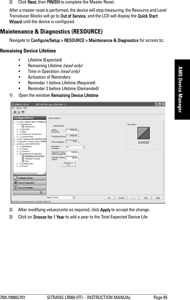
User Manual FF

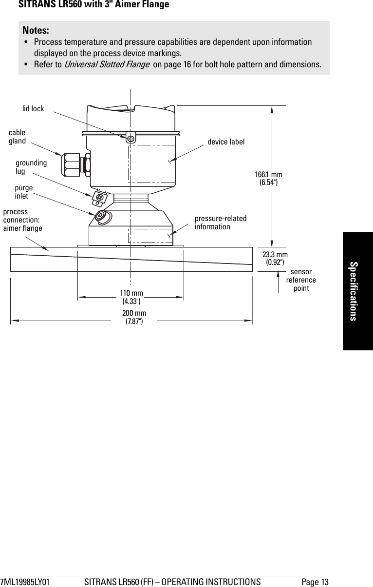
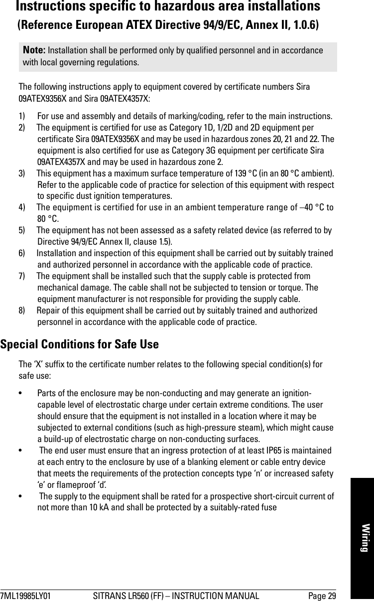
![Page 6 SITRANS LR560 (FF) – OPERATING INSTRUCTIONS 7ML19985LY01mmmmmSITRANS LR560 (FF)SITRANS LR560 OverviewSITRANS LR560 is a 2-wire, 78 GHz FMCW radar level transmitter for continuous monitoring of solids in vessels to a range of 100 m (329 ft). The plug and play performance is ideal for all solids applications, including those with extreme dust and high temperatures to +200 °C (+392 °F). The device consists of an electronic circuit coupled to a lens antenna and flange for quick and easy positioning. The main benefits of using 78 GHz over devices using lower frequency are:• very narrow beam, so device is insensitive to mounting nozzle interference and vessel obstructions.• short wavelength yields very good reflection properties on sloped solids, so aiming towards material angle of repose is usually not necessary.The technology is very tolerant of buildup on the lens antenna, however an air purge inlet is provided for periodic cleaning if required. SITRANS LR560 supports Foundation Fieldbus communication protocol, and AMS Device Manager software. Signals are processed using Process Intelligence which has been field-proven in over 1,000,000 applications worldwide (ultrasonic and radar). This device can be configured as an FF (H1) Link Master.ProgrammingSITRANS LR560 is very easy to install and configure via an optional graphical local display interface (LDI). You can modify the built-in parameters either locally, using the control buttons or the infrared handheld programmer, or from a remote location using one of the following options:•PROFIBUS PA [using SIMATIC PDM, or FDT (such as PACTware). See SITRANS LR560 (PROFIBUS PA) Instruction Manual for more information.]•HART [using handheld 375 Field Communicator, SIMATIC PDM, AMS, or FDT (such as PACTware). See SITRANS LR560 (mA/HART) Instruction Manual for more information.]•Foundation Fieldbus (FF) [using handheld 375 Field Communicator, an FF host system, or AMS]. Once programmed, the graphic Local Display Interface (LDI) can be removed if desired and used to transfer parameters to multiple SITRANS LR560s.](https://usermanual.wiki/Siemens-Canada-Siemens-Milltronics-Process-Instruments/LR560.User-Manual-FF/User-Guide-2312647-Page-12.png)
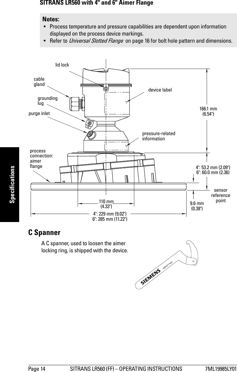
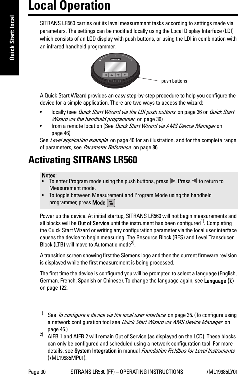
![7ML19985LY01 SITRANS LR560 (FF) – OPERATING INSTRUCTIONS Page 9mmmmmSpecificationsInterfaceCommunication• Foundation Fieldbus• ITK version 5 Blocks supported: RESOURCE, LTB, AIFB1, AIFB2, PID, LCD, DIAGBlock execution time: AIFB - 30 ms, PID - 100 msConfiguration• remote FF host system or Emerson AMS version 9.0 (PC)• local Siemens Milltronics infrared handheld programmer [seeProgrammer (infrared keypad) on page 11], or Field Communicator 375 [see Field Communicator 375 (FC375) on page 147], or local control buttonsOptional removablelocal display interface (LDI)1) graphic LCD, with bar graph representing levelMechanicalProcess Connections:• universal flat-faced flanges2) 3"/80 mm, 4"/100 mm, 6"/150 mm- materials stainless steel 316L (1.4404 or 1.4435), or 304• Aimer flanges2) 3"/80 mm, 4"/100 mm, 6"/150 mm- material polyurethane powder-coated cast aluminumEnclosure • construction 316L/1.4404 stainless steel• conduit entry M20x1.5, or ½" NPT • conduit entry connector M12 connector (shipped with M20 to M12 adaptor) (optional) or 7/8" connector (shipped with 1/2" NPT to 7/8" adaptor)• ingress protection Type 4X/NEMA 4X, Type 6/NEMA 6, IP68• lid with window polycarbonate (window material)Lens antenna material•construction - 40 m version PEI - 100 m version PEEK1) Display quality will be degraded in temperatures below –20 °C (–4 °F) and above +65°C (+149 °F).2) Universal flange mates with EN 1092-1 (PN16)/ASME B16.5 (150 lb)/JIS 2220 (10K) bolt hole pattern.](https://usermanual.wiki/Siemens-Canada-Siemens-Milltronics-Process-Instruments/LR560.User-Manual-FF/User-Guide-2312647-Page-15.png)
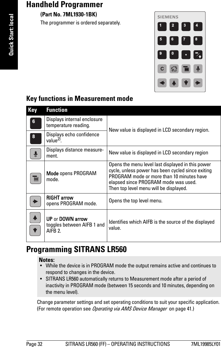
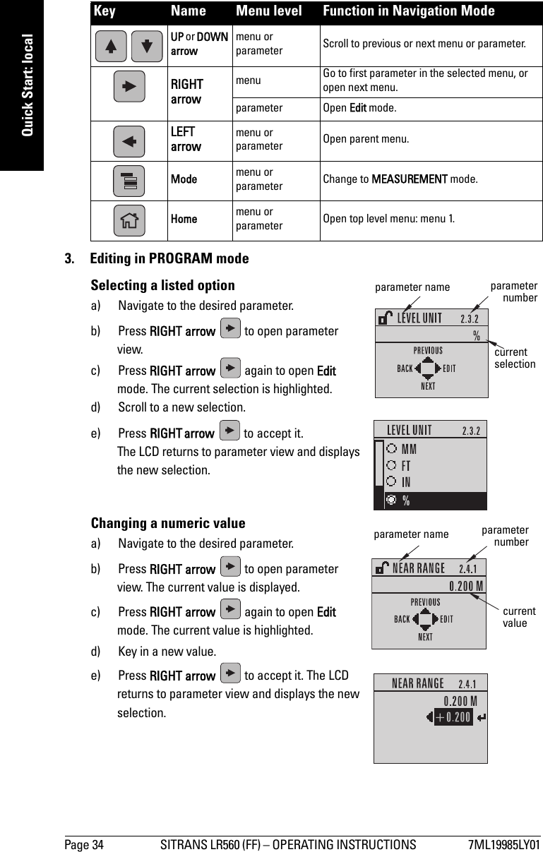
![7ML19985LY01 SITRANS LR560 (FF) – OPERATING INSTRUCTIONS Page 31mmmmmQuick Start: localThe LCD DisplayMeasurement modeNormal operation 1) 2)Fault presentProgram modeNavigation view• A visible menu bar indicates the menu list is too long to display all items.• The depth of the item band on the menu bar indicates the length of the menu list: a deeper band indicates fewer items.• The position of the item band indicates the approximate position of the current item in the list. A band halfway down the menu bar indicates the current item is halfway down the list. 1) Press UP or DOWN arrow to switch.2) In response to a key press request. For details, see Key functions in Measurement mode on page 32.M[]FB 121.40 °CNO DATA EXCH.18.91678134251 – toggle indicator1) to switch between AIFB 1/AIFB 2 (displayed as FB1/FB2)2 – identifies which block is source of displayed value3 – measured value (level, distance)4 – units5 – bar graph indicates level6 – secondary region indicates on request2) electronics temperature, echo confidence, or distance7 – text area displays status messages 8 – device status indicator7 – text area displays a fault code and an error message8 – service required icon appearsS: 0 LOEcurrent item numbercurrent itemcurrent menu item bandmenu bar parameter value/selectionparameter nameParameter view Edit viewparameter number](https://usermanual.wiki/Siemens-Canada-Siemens-Milltronics-Process-Instruments/LR560.User-Manual-FF/User-Guide-2312647-Page-37.png)
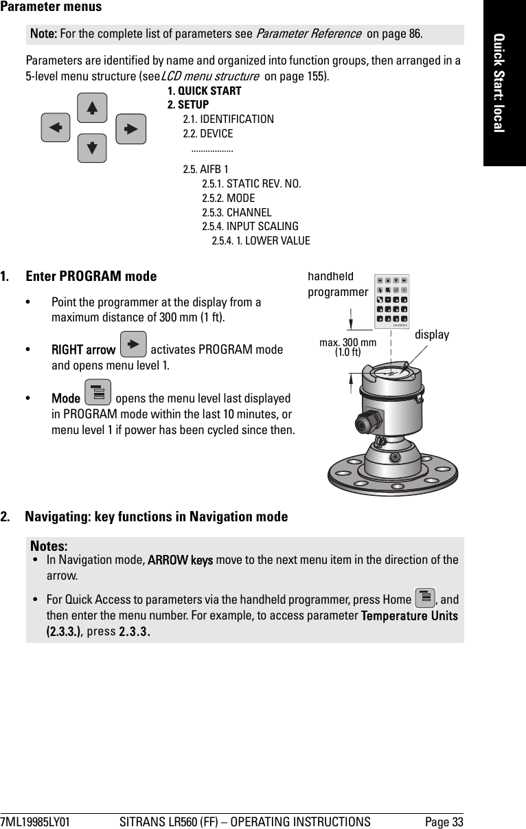
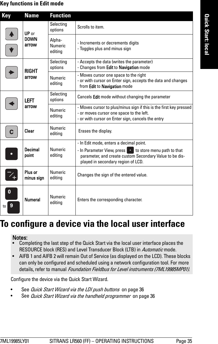
![Page 40 SITRANS LR560 (FF) – OPERATING INSTRUCTIONS 7ML19985LY01mmmmmQuick Start: localLevel application exampleThe application is a vessel that takes an average 3 hours (180 minutes) to fill and 3 weeks to empty.Fill rate = 0.08 m/minute [(Low Cal Pt. minus High Cal Pt.) / fastest of fill or empty time]= (15.5 m – 1 m) / 180 min. = 14.5 m /180 min. = 0.08 m/min.Therefore SLOW response rate (0.1 m/minute) can be selected. Quick Start Parameter Setting Description Vessel STEELResponse Rate SLOW Resets Fill Rate and Empty Rate to 0.1 m/minute.Units MLow Calibration Point 15.5 Process empty level.High Calibration Point 1.0 Process full level.Wizard Complete FINISH Save new settings and exit WizardSensor Reference Point level Low Calibration PointHigh Calibration Point15.5 m1.0 mSITRANS LR560](https://usermanual.wiki/Siemens-Canada-Siemens-Milltronics-Process-Instruments/LR560.User-Manual-FF/User-Guide-2312647-Page-46.png)
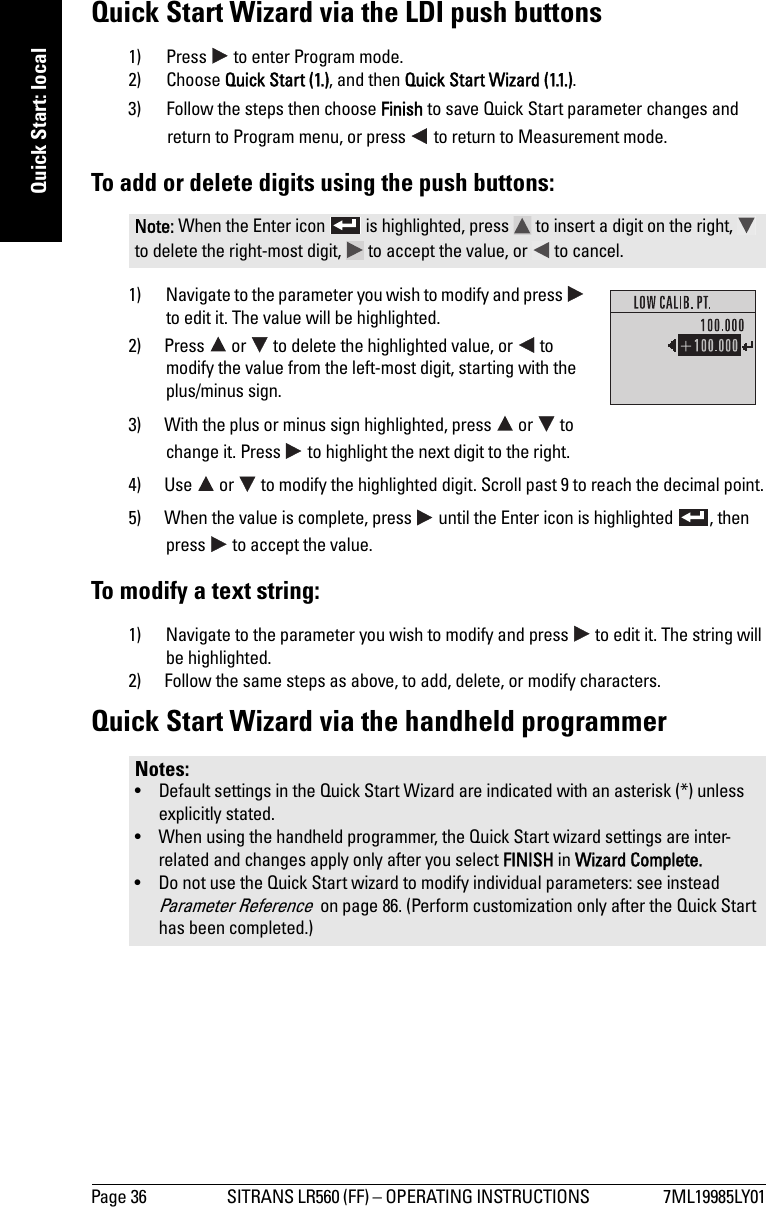
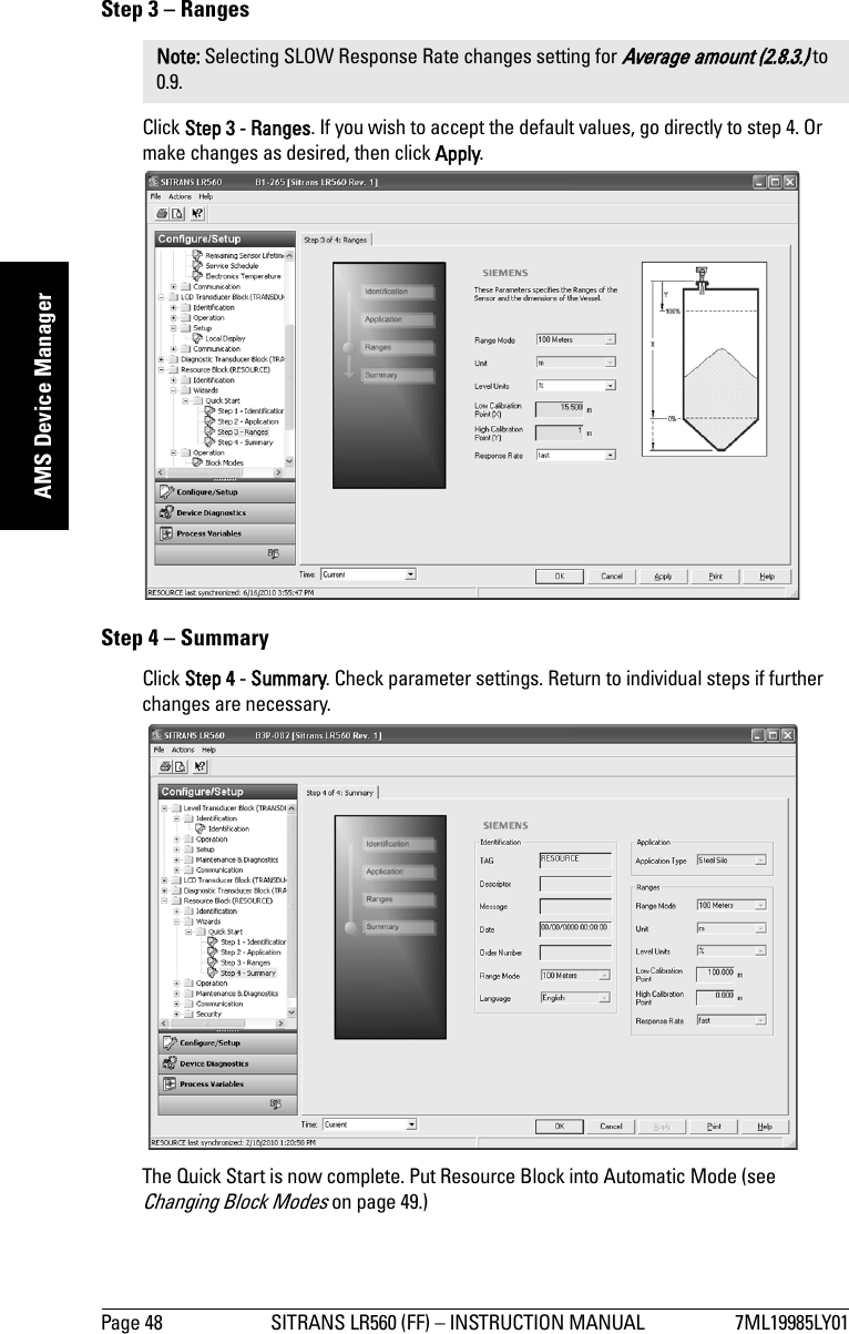
![7ML19985LY01 SITRANS LR560 (FF) – INSTRUCTION MANUAL Page 47mmmmmAMS Device ManagerStep 1 – IdentificationClick Step 1 - Identification.If you wish to accept the default values, go directly to Step 2 (Descriptor, Message, and Date fields can be left blank). Or if desired, make changes then click Apply. Step 2 – ApplicationClick Step 2 - Application. If you wish to accept the default values, go directly to Step 3.Or select a different vessel type (steel or concrete). [This changes the setting for Position Detect (2.4.5.2.) to Rising Edge.] Then click Apply.Notes: • Selecting either STEEL or CONCRETE does a functional reset (see Master Reset (4.1.) on page 110).• Selecting STEEL changes the setting for Position Detect (2.7.3.3.) to Rising Edge. and for Algorithm (2.7.3.1.) to F.• Selecting CONCRETE changes the setting for Position Detect (2.7.3.3.) to Rising Edge and for Algorithm (2.7.3.1.) to ALF.](https://usermanual.wiki/Siemens-Canada-Siemens-Milltronics-Process-Instruments/LR560.User-Manual-FF/User-Guide-2312647-Page-53.png)

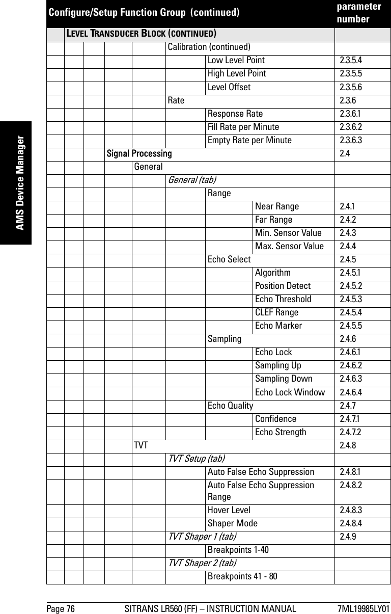
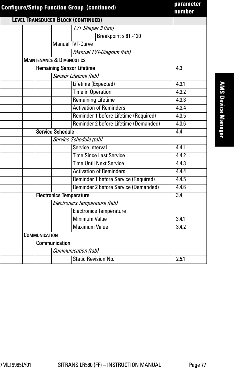
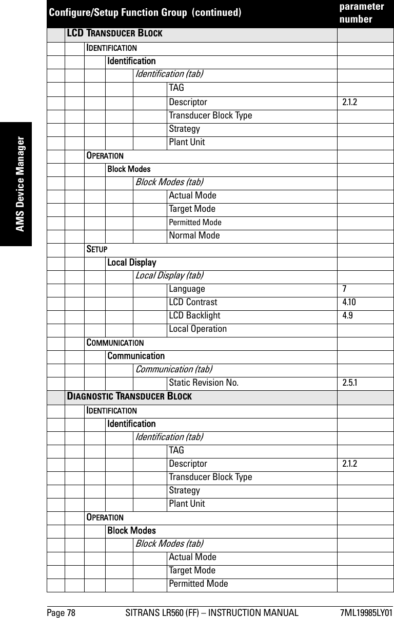
![Page 58 SITRANS LR560 (FF) – INSTRUCTION MANUAL 7ML19985LY01mmmmmAMS Device ManagerElectronics Temperature • Electronics Temperature Displays the current internal temperature of the device• Minimum Value •Maximum Value Communication (LTB)Navigate to Configure/Setup > LTB > Communication for access to:Communication:• Static Revision No.[see Static Revision Number (2.5.1.) on page 103]](https://usermanual.wiki/Siemens-Canada-Siemens-Milltronics-Process-Instruments/LR560.User-Manual-FF/User-Guide-2312647-Page-64.png)
![Page 60 SITRANS LR560 (FF) – INSTRUCTION MANUAL 7ML19985LY01mmmmmAMS Device ManagerLocal Display (continued)• Local Operation If local operation is disabled remotely and no communication activity exists for 30 seconds, the parameter is made visible again locally.Communication (LCD)Navigate to Configure/Setup > LCD > Communication for access to: Communication:• Static Revision No.[see Static Revision Number (2.5.1.) on page 103]](https://usermanual.wiki/Siemens-Canada-Siemens-Milltronics-Process-Instruments/LR560.User-Manual-FF/User-Guide-2312647-Page-66.png)
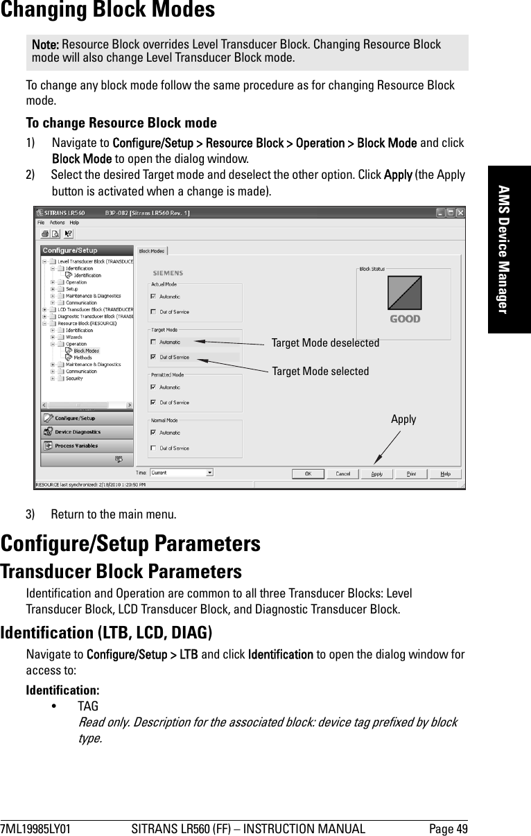
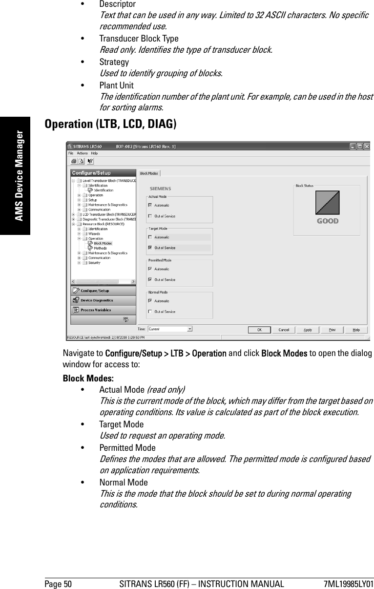
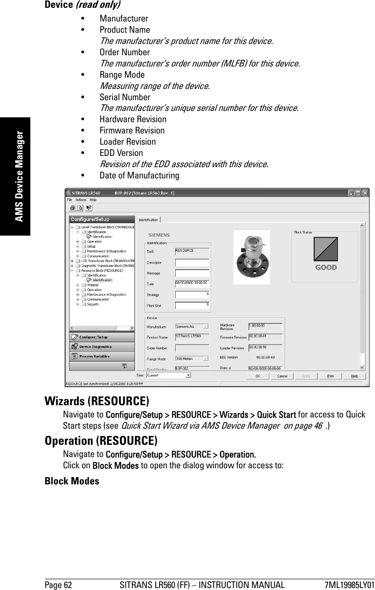
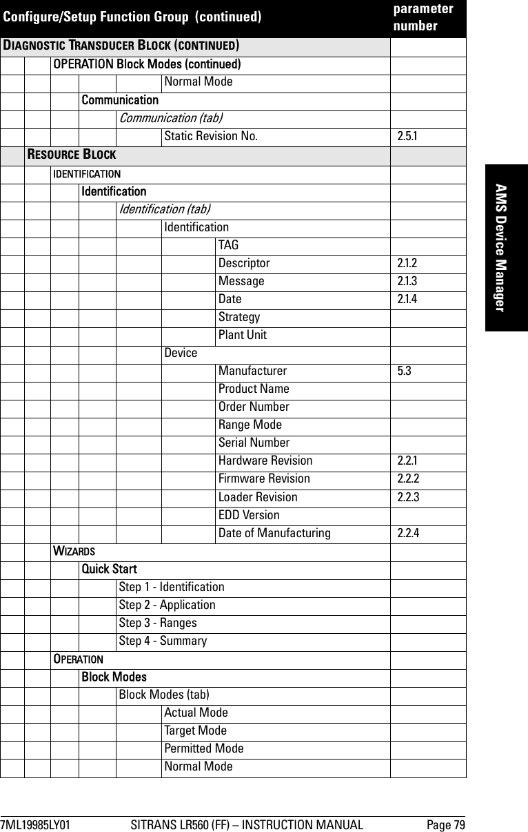
![7ML19985LY01 SITRANS LR560 (FF) – INSTRUCTION MANUAL Page 61mmmmmAMS Device ManagerConfigure/Setup (Diagnostic Transducer Block-DIAG)Identification (DIAG)Navigate to Configure/Setup > DIAG > Identification.Identification (see Identification (LTB, LCD, DIAG) on page 49):Operation (DIAG)Navigate to Configure/Setup > DIAG > Operation. (See Operation (LTB, LCD, DIAG) on page 50.)Communication (DIAG)Navigate to Configure/Setup > DIAG > Communication. Communication:• Static Revision No. [see Static Revision Number (2.5.1.) on page 103]Configure/Setup (Resource Block - RESOURCE)Identification (RESOURCE)Navigate to Configure/Setup > RESOURCE > Identification for access to: Identification•TAG Read only. Description for the associated block: device tag prefixed by block type.• Descriptor• Message • Date (Installation Date)The user entered date on which the device was installed in the system.• StrategyUsed to identify grouping of blocks.• Plant UnitThe identification number of the plant unit. For example, can be used in the host for sorting alarms.Note: Parameters in the Diagnostic Transducer Block used solely by factory personnel.Notes: • For a complete list of parameters accessible via AMS, see AMS Menu Structure on page 75.• For parameters followed by a reference number, additional information is available in Parameter Reference on page 86.](https://usermanual.wiki/Siemens-Canada-Siemens-Milltronics-Process-Instruments/LR560.User-Manual-FF/User-Guide-2312647-Page-67.png)
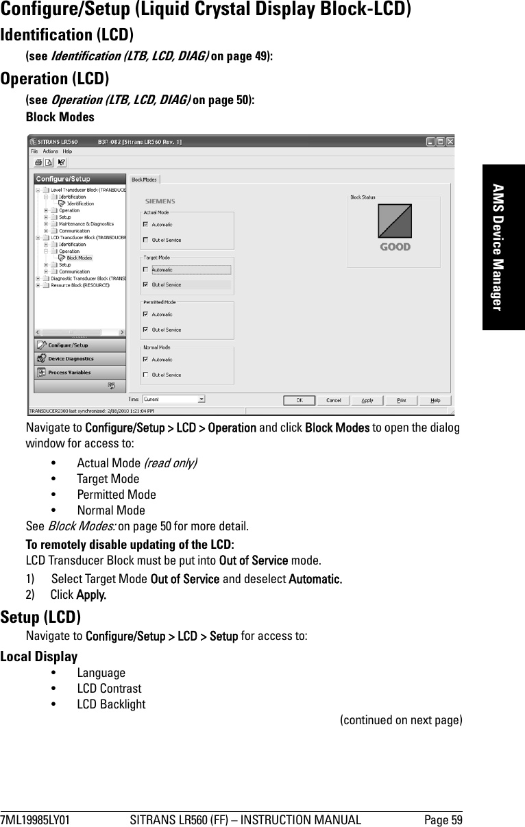
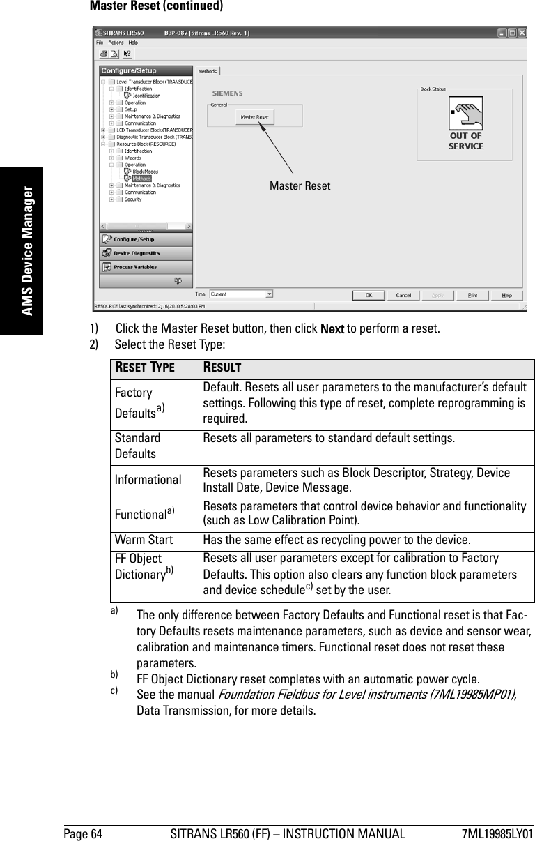
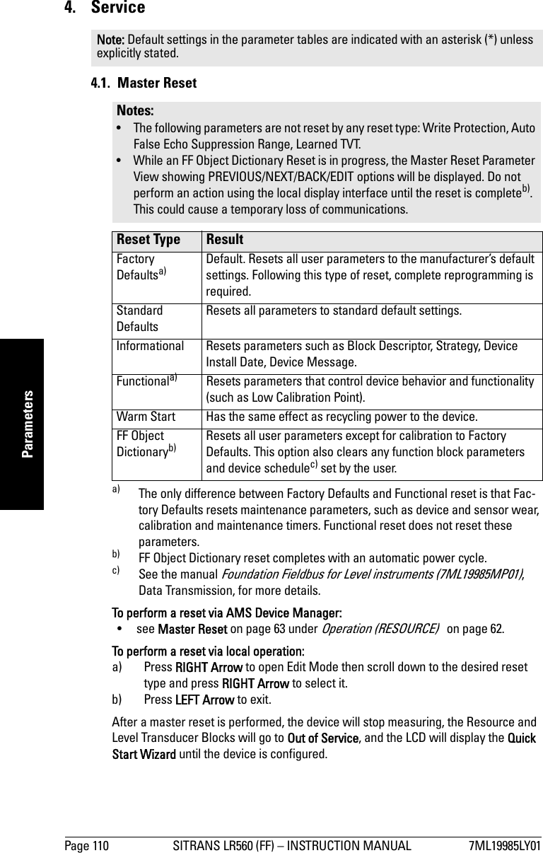
![7ML19985LY01 SITRANS LR560 (FF) – INSTRUCTION MANUAL Page 63mmmmmAMS Device ManagerBlock Modes (continued) [see Block Modes: on page 50]• Actual Mode• Target Mode• Permitted Mode• Normal ModeMethodsClick Methods to open the dialog window for access to:Master Reset1)(continued on next page)NOTE: If the RESOURCE block is set to Out of Service, the LTB, and AIFB blocks are forced to Out of Service also, but the LCD and DIAG blocks remain in Automatic mode.Notes: • RESOURCE and LTB Block Status must be Out of Service before a Master Reset can be performed (see Changing Block Modes on page 49).• The following parameters are not reset by any reset type: Write Protection, Auto False Echo Suppression Range, Learned TVT.• While an FF Object Dictionary Reset is in progress, the Master Reset Parameter View showing PREVIOUS/NEXT/BACK/EDIT options will be displayed. Do not perform an action using the local display interface until the reset is complete1). This could cause a temporary loss of communications.1) FF Object Dictionary reset completes with an automatic power cycle.](https://usermanual.wiki/Siemens-Canada-Siemens-Milltronics-Process-Instruments/LR560.User-Manual-FF/User-Guide-2312647-Page-69.png)
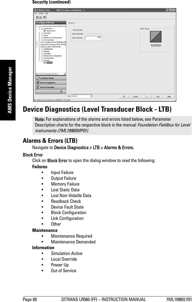
![7ML19985LY01 SITRANS LR560 (FF) – INSTRUCTION MANUAL Page 67mmmmmAMS Device ManagerCommunication (RESOURCE)Navigate to Configure/Setup > RESOURCE > Communication to read the following: • Manufacturer • Device TypeManufacturer’s model number associated with the device• Device Revision •DD Revision Revision of the DD (also called EDD) associated with this device.•ITK Version • Static Revision No.[see Static Revision Number (2.5.1.) on page 103]Security (RESOURCE)Navigate to Configure/Setup > RESOURCE > Security to access:Security• Write Protection[see Security (continued) on page 68]See also Password Protection on page 74.(continued on next page)](https://usermanual.wiki/Siemens-Canada-Siemens-Milltronics-Process-Instruments/LR560.User-Manual-FF/User-Guide-2312647-Page-73.png)
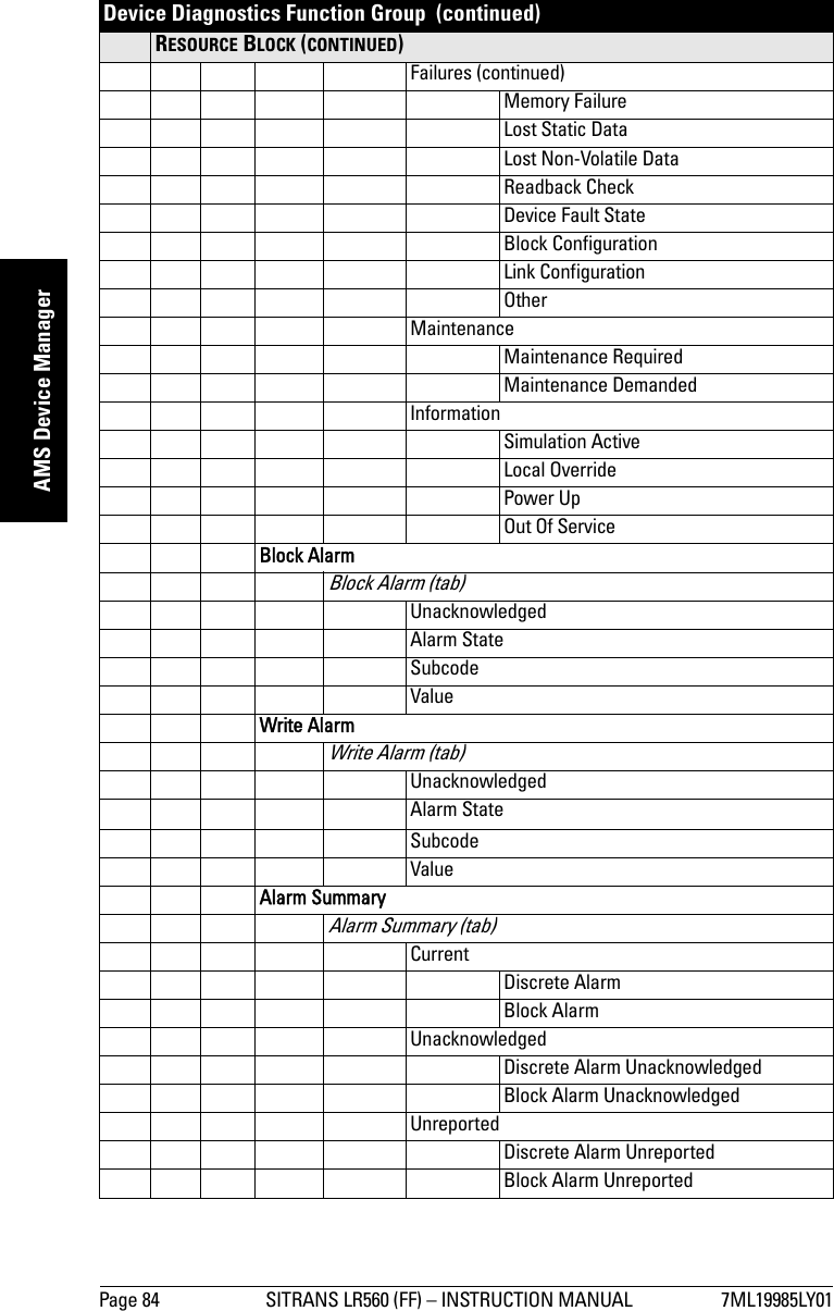
![7ML19985LY01 SITRANS LR560 (FF) – INSTRUCTION MANUAL Page 69mmmmmAMS Device ManagerXD Error• Transducer ErrorBlock AlarmClick on Block Alarm to open the dialog window to read the following:Unacknowledged• UnacknowledgedAlarm State•Alarm StateSubcode•SubcodeValue•Value1) From the Block Error tab, check the Maintenance window to display the level of maintenance alarm that is active.2) From the Block Alarm tab, check the Alarm State window to display the level of maintenance alarm that has been acknowledged.3) From the Block Alarm tab, in the Unacknowledged window, select Acknowledged to acknowledge an alert.Note: Acknowledging a maintenance reminder from the device [see Acknowledge (4.2.9.), Acknowledge (4.3.9.), Acknowledge (4.4.9.), Acknowledge (4.5.9.)], will not set the Block Alarm to Acknowledged in AMS. The maintenance alarm will cause an FF block alert, and the block alert can only be acknowledged via a remote host such as NI-FBUS-Configurator or AMS Device Manager (as in step 3 above).](https://usermanual.wiki/Siemens-Canada-Siemens-Milltronics-Process-Instruments/LR560.User-Manual-FF/User-Guide-2312647-Page-75.png)
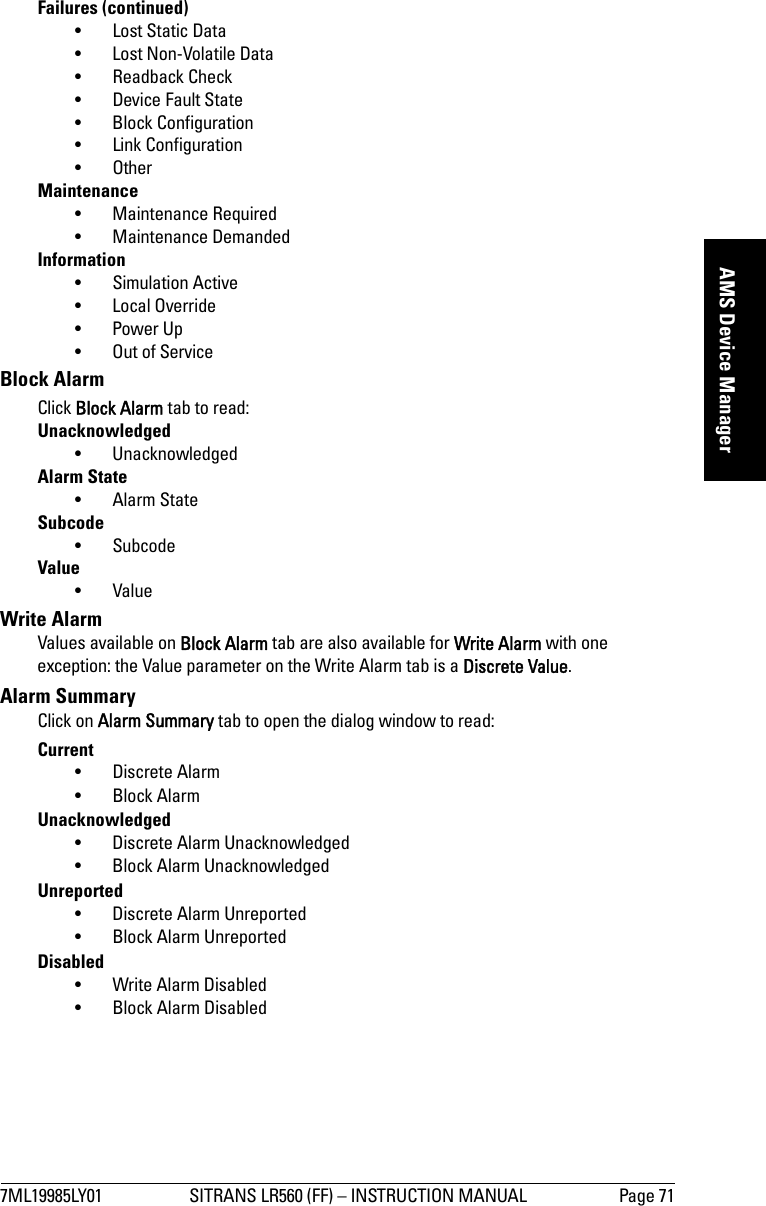
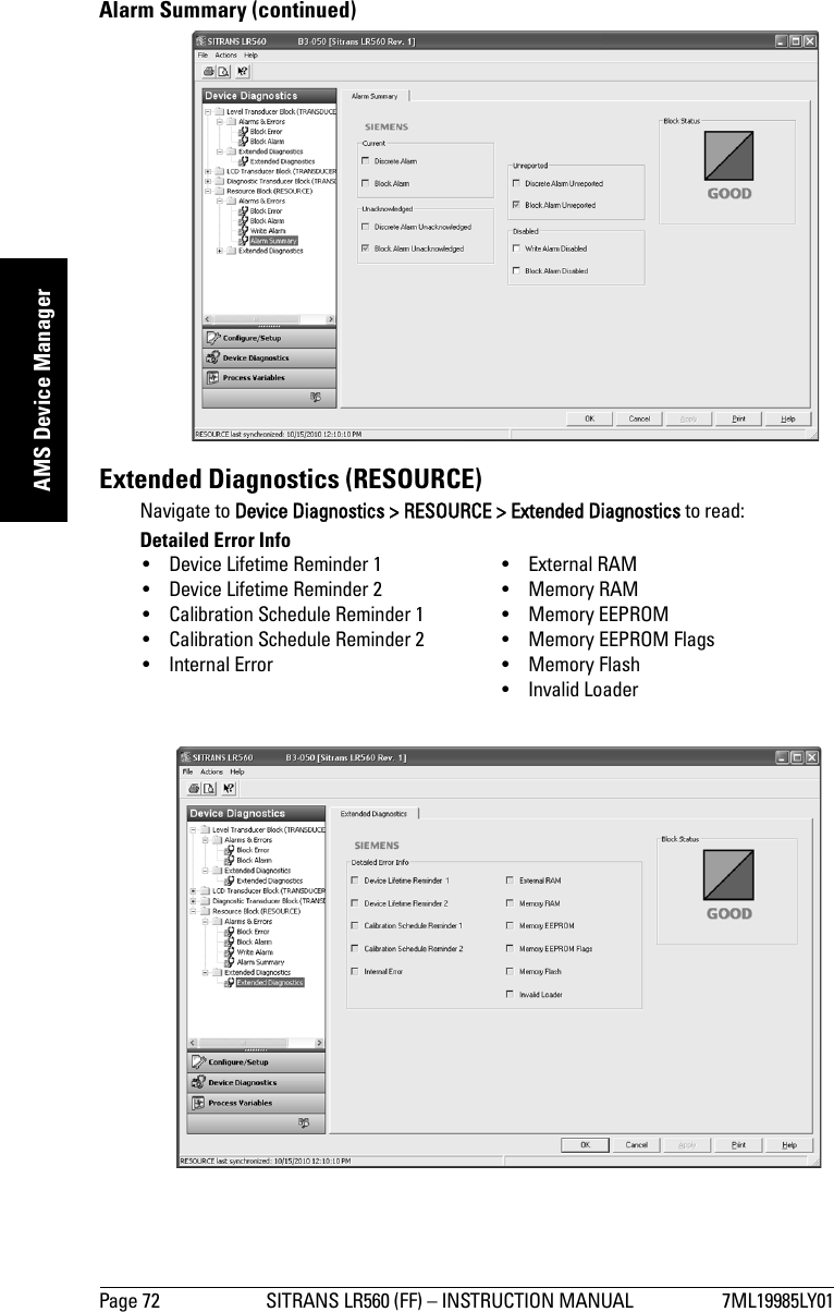
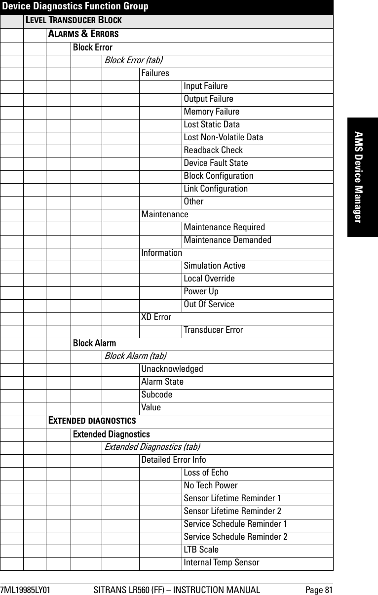
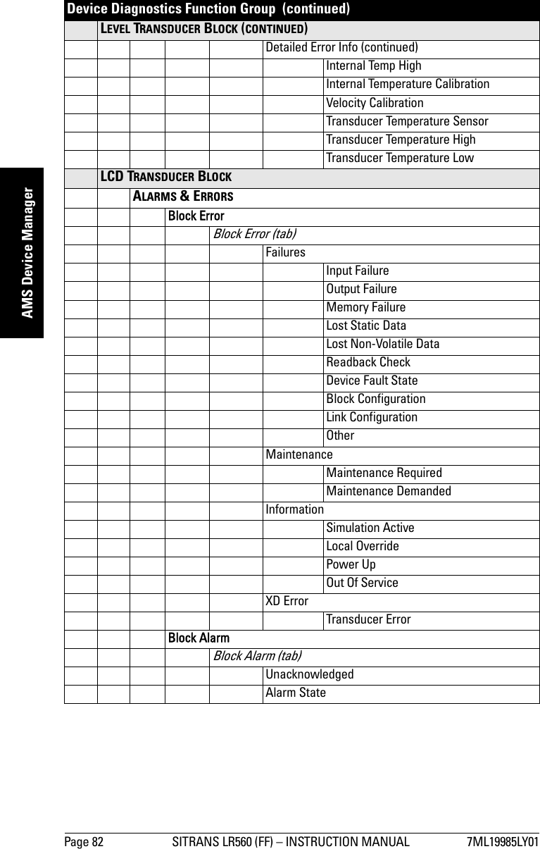
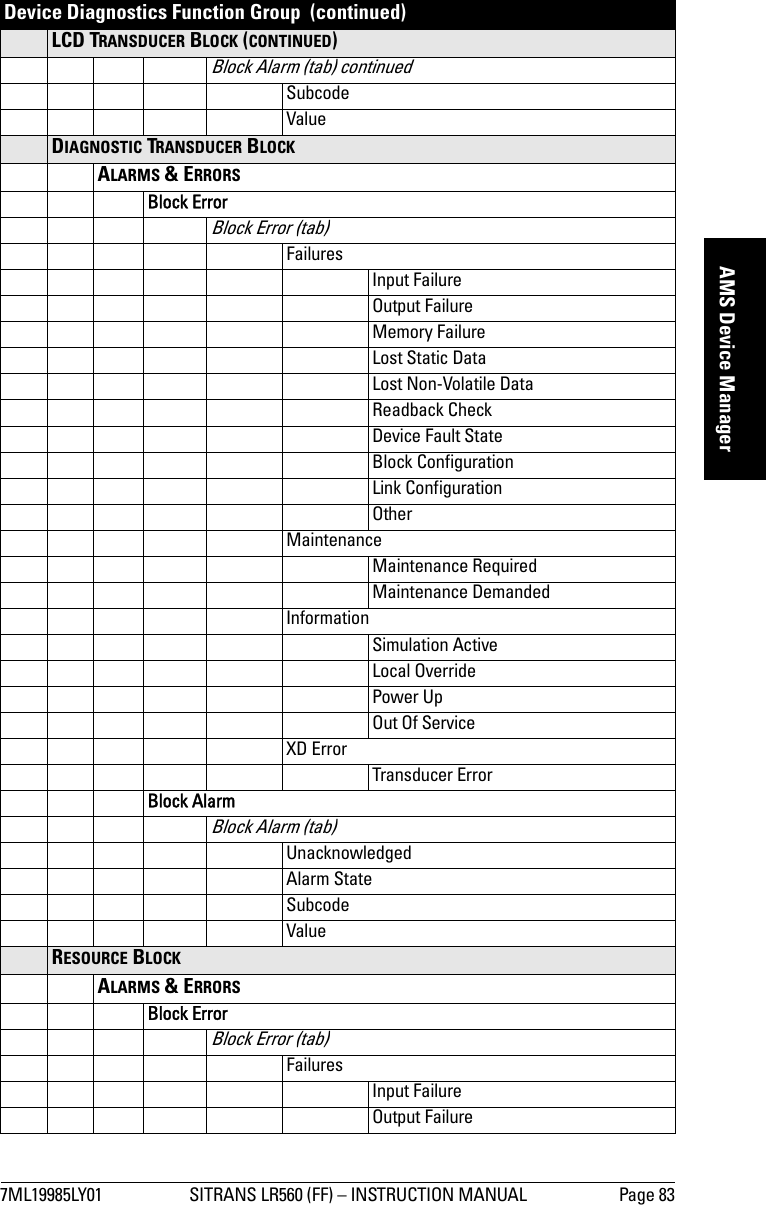
![Page 70 SITRANS LR560 (FF) – INSTRUCTION MANUAL 7ML19985LY01mmmmmAMS Device ManagerExtended Diagnostics (LTB)Navigate to Device Diagnostics > LTB > Extended Diagnostics to read the following:Detailed Error Info• Loss of Echo• No Tech Power• Sensor Lifetime Reminder 1• Sensor Lifetime Reminder 2• Service Schedule Reminder 1• Service Schedule Reminder 2• LTB Scale• Internal Temperature Sensor• Internal Temperature High• Internal Temperature Calibration• Velocity Calibration• Transducer Temperature Sensor• Transducer Temperature High• Transducer Temperature LowDevice Diagnostics (Level Control Device Block - LCD)Alarms & Errors (LCD)Navigate to Device Diagnostics > LCD > Alarms & Errors to read Block and Alarm errors. [Errors displayed are the same for each block (LTB, LCD, DIAG, RESOURCE). See Alarms & Errors (LTB) on page 68 for full listing.]Device Diagnostics (Diagnostic Transducer Block - DIAG)Alarms & Errors (DIAG)Navigate to Device Diagnostics > DIAG > Alarms & Errors to read Block and Alarm errors. [Errors displayed are the same for each block (LTB, LCD, DIAG, RESOURCE). See Alarms & Errors (LTB) on page 68 for full listing. See AMS Device Manager instruction manual to work with alarms and errors.]Device Diagnostics (Resource Block - RESOURCE)Alarms & Errors (RESOURCE)Navigate to Device Diagnostics > RESOURCE > Alarms & Errors.Block ErrorClick Block Error tab to read:Failures• Input Failure• Output Failure• Memory FailureFailures](https://usermanual.wiki/Siemens-Canada-Siemens-Milltronics-Process-Instruments/LR560.User-Manual-FF/User-Guide-2312647-Page-76.png)

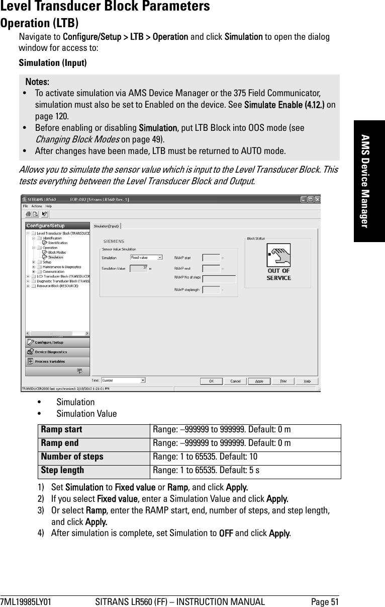
![Page 120 SITRANS LR560 (FF) – INSTRUCTION MANUAL 7ML19985LY01mmmmmParameters4.11. Secondary ValueThe value displayed in the secondary region of the LCD, in Measurement Mode . [See The LCD Display on page 31, area (6) under Normal operation.]Use Secondary Value to capture the menu navigation path to a selected parameter, and store a custom secondary value [for example, Echo Strength (2.4.7.2.)].While in Parameter View1) mode of the selected parameter, press the decimal point key. This stores the path to the selected parameter in Secondary Value, and displays that value in the secondary region of the LCD display when in Measurement Mode. 4.12. Simulate EnableReplaces a physical jumper switch found on some FF devices to enable simulation when set to ON. (Available only via local operation.)For more information on Simulation, see Simulation (Input) on page 51 in AMS Device Manager, or the manual, Foundation Fieldbus for Level instruments (7ML19985MP01).4.13. Demo ModeReduces the time between measurements and the accuracy for demonstration purposes.5. Communication5.1. TagThe user-defined description for the device.To access this parameter via AMS Device Manager see Identification under Identification (RESOURCE) on page 61.1) See Parameter view on page 31, under Program mode.Options * OFF Simulation DisabledON Simulation EnabledNote: Default settings in the parameter tables are indicated with an asterisk (*) unless explicitly stated.](https://usermanual.wiki/Siemens-Canada-Siemens-Milltronics-Process-Instruments/LR560.User-Manual-FF/User-Guide-2312647-Page-126.png)
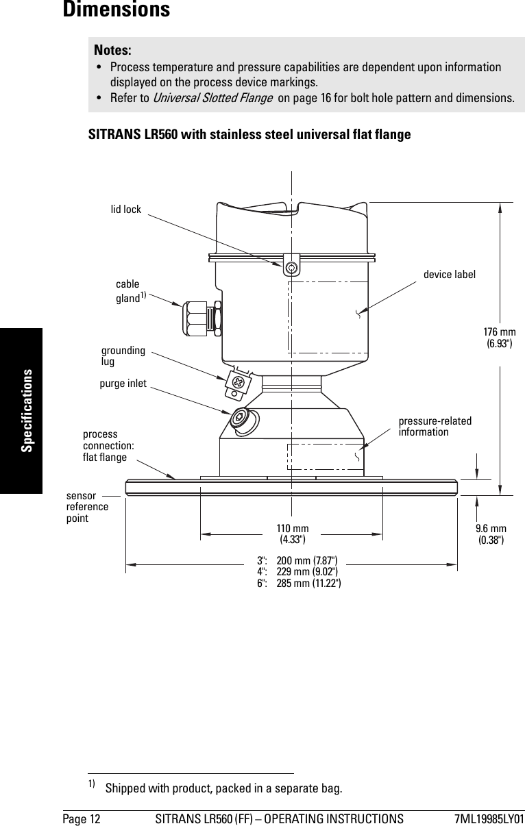
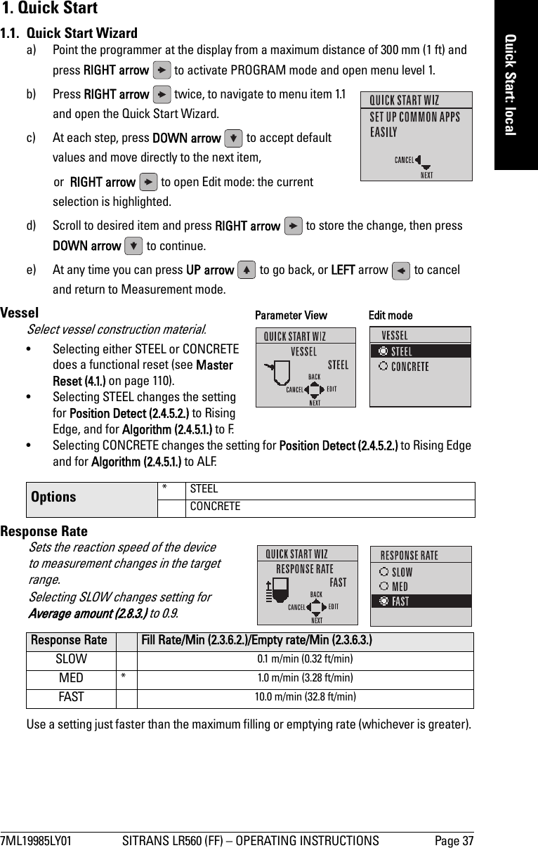
![7ML19985LY01 SITRANS LR560 (FF) – INSTRUCTION MANUAL Page 137mmmmmD: Technical ReferenceAppendix D: Technical ReferencePrinciples of Operation SITRANS LR560 is a 2-wire 78 GHz FMCW radar level transmitter for continuous monitoring of solids in vessels1). Radar level measurement uses the time of flight principle to determine distance to a material surface. FMCW radar transmits a continuous wave. The frequency of the wave is constantly increasing: this is known as the sweep. By the time the first part of the wave has been reflected off the target and returned to the device, the part of the wave that is just being emitted is at a higher frequency. The difference in frequency between the transmitted and received signals is proportional to time of flight. Electromagnetic wave propagation is virtually unaffected by temperature or pressure changes, or by changes in the vapor levels inside a vessel. Electromagnetic waves are not attenuated by dust.SITRANS LR560 consists of an enclosed electronic circuit coupled to an antenna and process connection. The electronic circuit generates a radar signal (78 GHz) that is directed to the antenna.The signal is emitted from the antenna, and the reflected echoes are digitally converted to an echo profile. The profile is analyzed to determine the distance from the sensor reference point2) to the material surface. This value (sensor value) is used as a basis for calculating the display of material level.Process VariablesThe Process Variables are sensor value and measured value. Sensor value is the distance from the sensor reference point (flange face) to the material surface. Since LR560 does not support Volume, the Measured value can be either Level (distance from low calibration point to material surface), or Distance (distance from sensor reference point to the material surface). Note: Where the number follows the parameter name [for example, Algorithm (2.4.5.1.)] this is the parameter access number via the handheld programmer. See Parameter Reference on page 86 for a complete list of parameters.1) The microwave output level is significantly less than that emitted from cellular phones.2) See Dimensions on page 12.](https://usermanual.wiki/Siemens-Canada-Siemens-Milltronics-Process-Instruments/LR560.User-Manual-FF/User-Guide-2312647-Page-143.png)