Siemens 277IWLAN-V100 Mobile Panel 277 IWLAN User Manual Mobile Panel 277F IWLAN
Siemens AG Mobile Panel 277 IWLAN Mobile Panel 277F IWLAN
UserManual.wiki
>
Siemens
>
277IWLAN-V100 User Manual
>
UserMan2
Contents
1.
UserMan1
2.
UserMan2
3.
UserMan Statement
4.
UserMan Statements
UserMan2
Navigation menu
Upload a User Manual
Namespaces
Wiki Guide
HTML
PDF
Info
Views
User Manual
Discussion / Help
Navigation

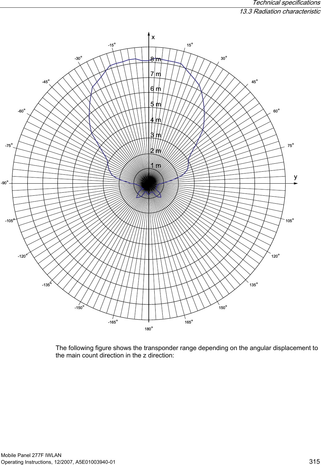
![Technical specifications 13.3 Radiation characteristic Mobile Panel 277F IWLAN 314 Operating Instructions, 12/2007, A5E01003940-01 13.3 Radiation characteristic 13.3.1 Radiation characteristic of the transponder Antenna type Dual port patch antenna Polarization Vertical and horizontal Frequency band 2400 - 2483 MHz Antenna gain Max. in main count direction • Port 1: 2,6 dBic • Port 2: 2.7 dBic Impedance 50 Ω Full widths at half maximum, horizontal at 2.45 GHz 93° Full widths at half maximum, vertical at 2.45 GHz 90° Ranges depending on angular displacement to main count direction The following figure shows the coordinate system applied to the transponder. []\] The figure below shows the transponder range depending on the angular displacement to the main count direction in the y direction:](https://usermanual.wiki/Siemens/277IWLAN-V100.UserMan2/User-Guide-1034534-Page-150.png)
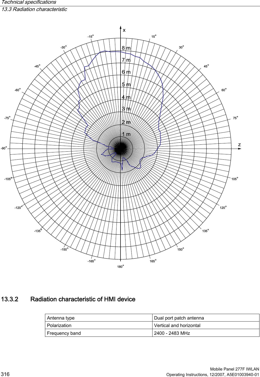
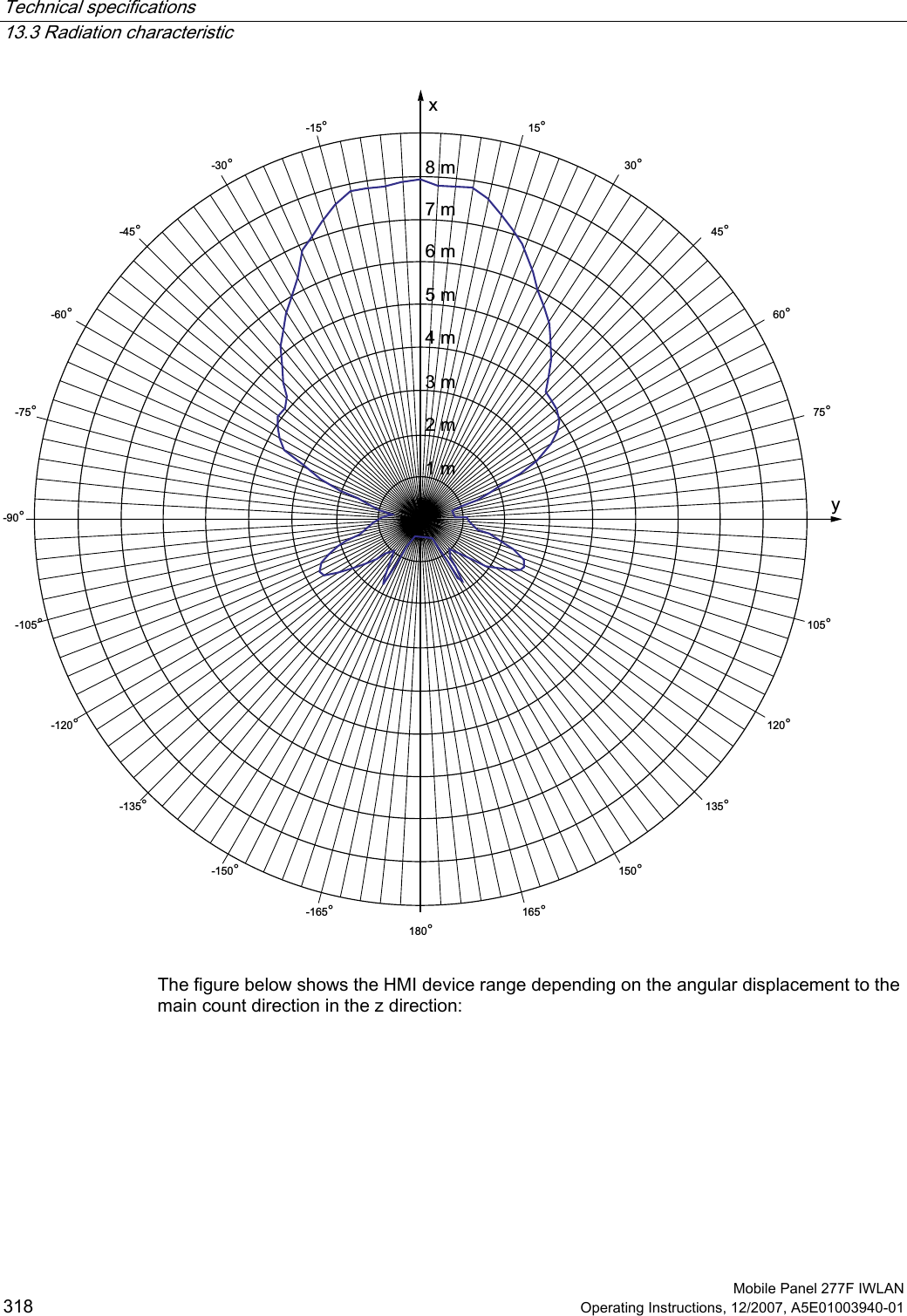
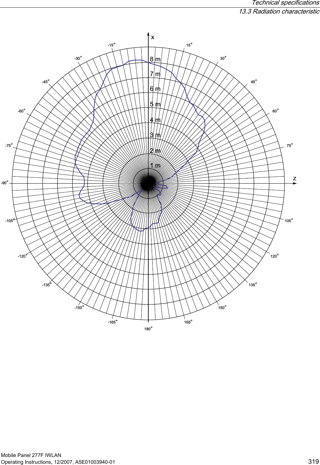
![Technical specifications 13.3 Radiation characteristic Mobile Panel 277F IWLAN Operating Instructions, 12/2007, A5E01003940-01 317 Antenna gain Max. in main count direction • Port 1: 2,6 dBic • Port 2: 2.7 dBic Impedance 50 Ω Full widths at half maximum, horizontal at 2.45 GHz 83° Full widths at half maximum, vertical at 2.45 GHz 80° Ranges depending on angular displacement to main count direction The figure below shows the coordinate system applied to the HMI device. \][] The figure below shows the HMI device range depending on the angular displacement to the main count direction in the y direction:](https://usermanual.wiki/Siemens/277IWLAN-V100.UserMan2/User-Guide-1034534-Page-153.png)