Siemens MD741-1 EGPRS/GSM Router User Manual 3173AD021 09 SIE EN
Siemens AG EGPRS/GSM Router 3173AD021 09 SIE EN
UserManual.wiki
>
Siemens
>
MD741-1 User Manual
>
UserMan
Contents
1.
UserMan1 MC75
2.
UserMan2 MC75
3.
UserMan
UserMan
Navigation menu
Upload a User Manual
Namespaces
Wiki Guide
HTML
PDF
Info
Views
User Manual
Discussion / Help
Navigation
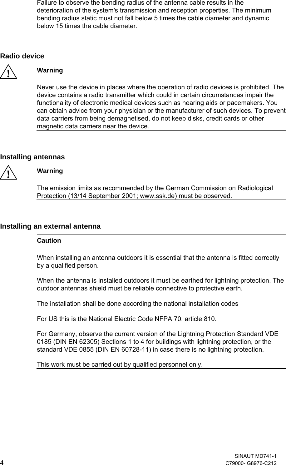
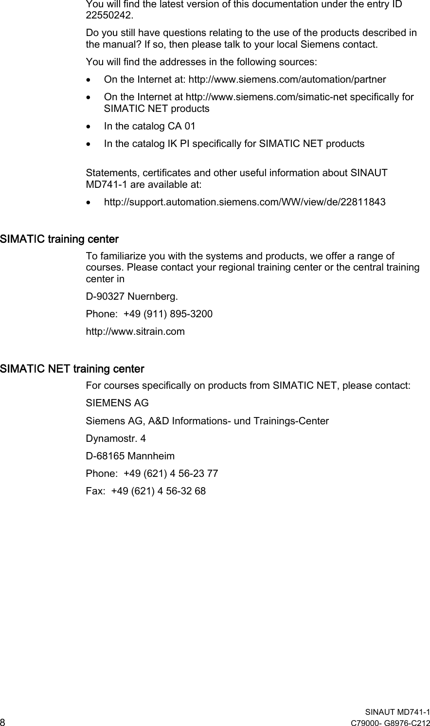
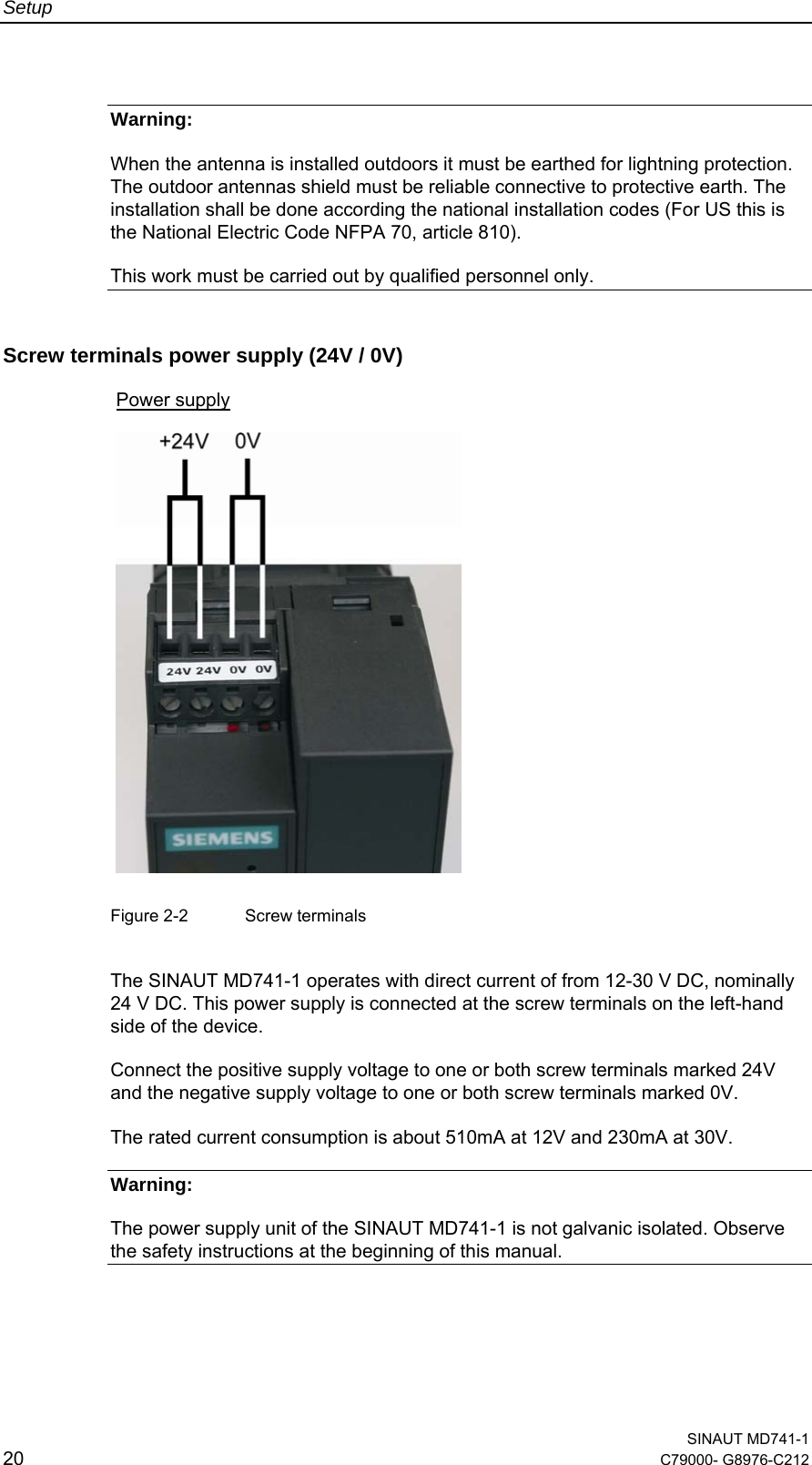
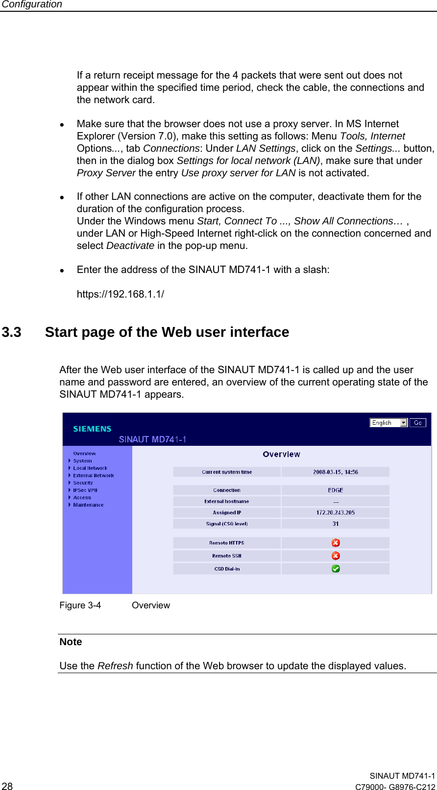
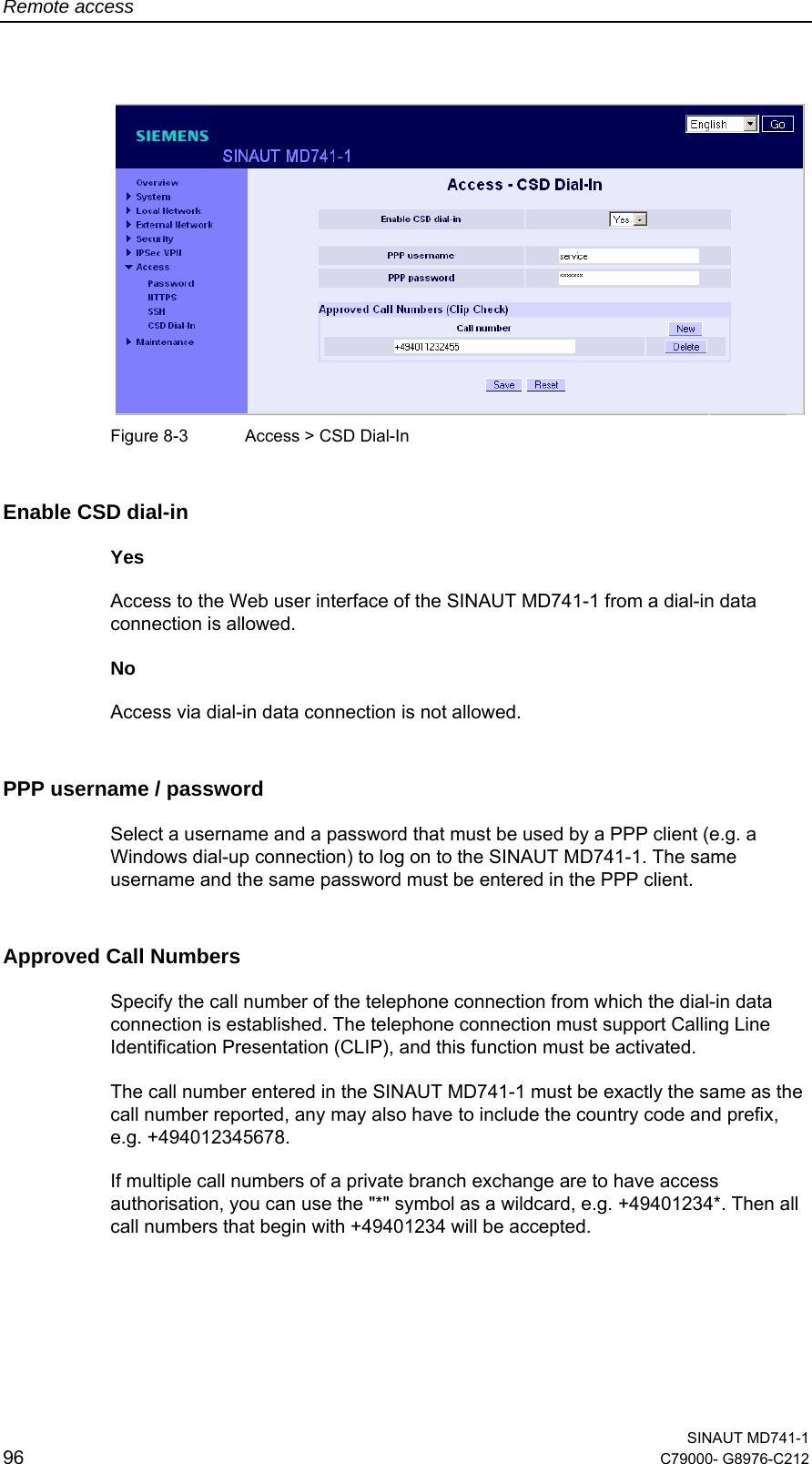


![Technical Data SINAUT MD741-1 116 C79000- G8976-C212 Max. transmitting power (acc. to output 99, V5) Class 4 (+33dBm ±2dB) for EGSM850 Class 4 (+33dBm ±2dB) for EGSM900 Class 1 (+30dBm ±2dB) for GSM1800 Class 1 (+30dBm ±2dB) for GSM1900 Class E2 (+27dBm ± 3dB) for GSM 850 8-PSK Class E2 (+27dBm ± 3dB) for GSM 900 8-PSK Class E2 (+26dBm +3 /-4dB) for GSM 1800 8-PSK Class E2 (+26dBm +3 /-4dB) for GSM 1900 8-PSK Antenna connection Nominal impedance: 50 ohms, jack: SMA Ambient conditions Temperature range Operation: -20 °C to +60 °C Storage: -40 °C to +70 °C Air humidity 0-95 %, non-condensing Housing Design Top-hat rail housing Material Plastic Protection class IP20 Dimensions 114 mm x 45 mm x 99 mm Weight approx. 280g DE CE Yes GSM/EGPRS module Conforms to GCF, PTCRB Environment The device complies with the European Directives RoHS and WEEE. Input voltage 12 - 30 V DC (24 V DC nominal) Input Current 510 – 230 mA DC Power input 4.4 W typical at 12 V 4.0 W typical at 24 V 4.5 W typical at 30 V Current consumption See table below. Power supply Input current characteristic 100020040060080012001400[mA][ms]10 20 30 40 50 7060 80 90 100IBurstat 12V4,62ms burst repeat rate 200400600800[mA][ms]10 20 30 40 50 7060 80 90 100IBurstat 24V4,62ms burst repeat rate](https://usermanual.wiki/Siemens/MD741-1.UserMan/User-Guide-941598-Page-116.png)
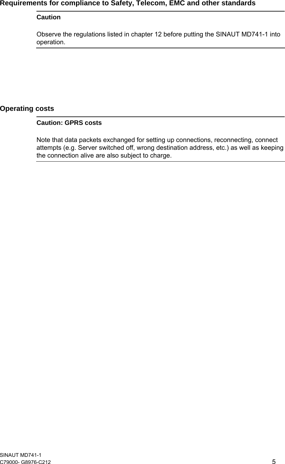
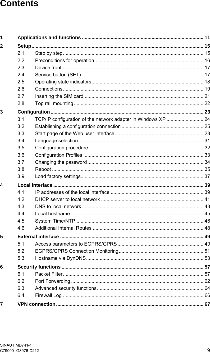
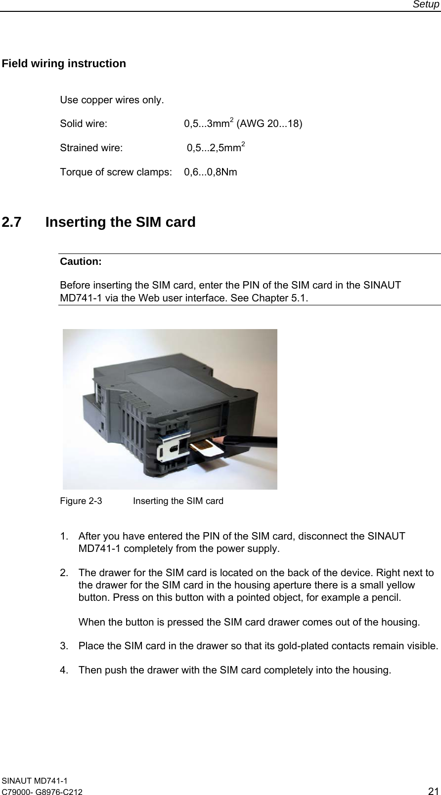
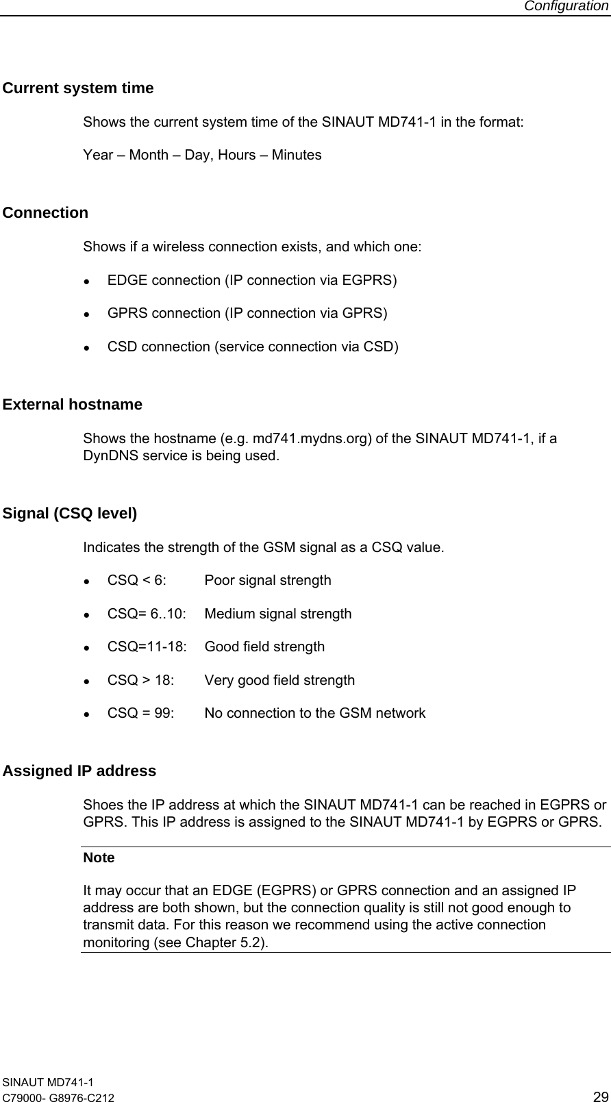
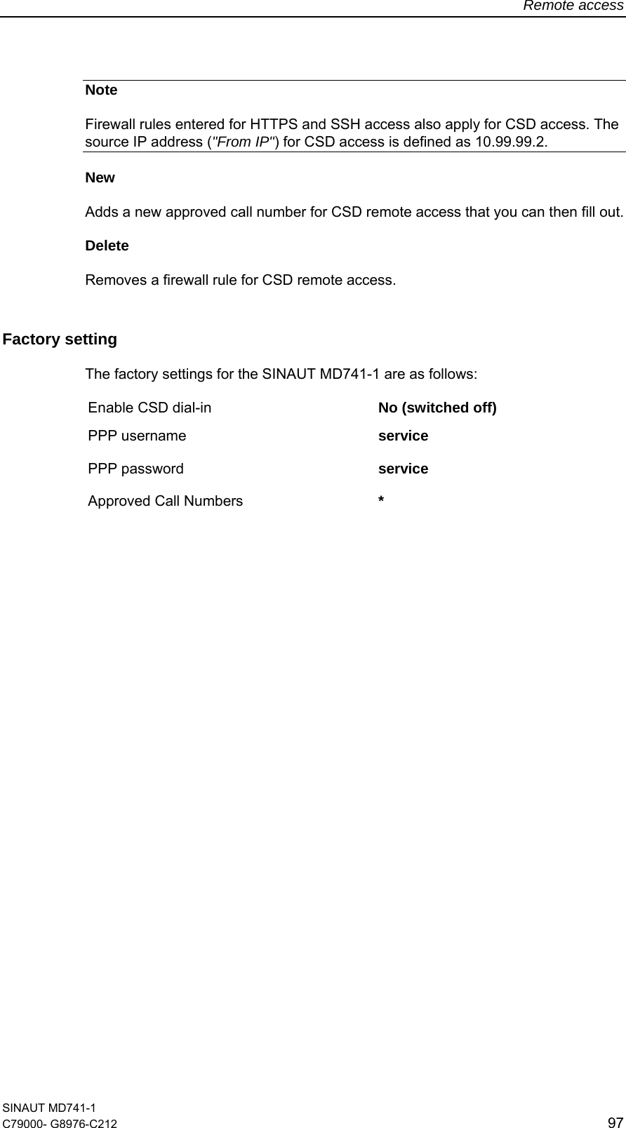
![Technical Data SINAUT MD741-1 C79000- G8976-C212 117 Current consumption (3) Input voltage Connected, no data transfer Continuous data transfer with low signal quality (1) Continuous data transfer with medium signal quality (2) Burst Operating mode [V] [mA] [mA] [mA] [mA] 12 174 315 263 1000 24 97 168 137 450 GSM-CSD 30 82 137 116 360 12 174 365 282 1260 24 97 182 147 550 EGPRS / GPRS 30 82 150 121 420 (1) Measured at GSM900 Power Level 5 (33dBm transmitting power) (2) Measured at GSM900 Power Level 10 (23dBm transmitting power) (3) USB port not used](https://usermanual.wiki/Siemens/MD741-1.UserMan/User-Guide-941598-Page-117.png)