Siemens RF350R02 RFID Reader 13.56 MHz User Manual SIMATIC RF300
Siemens AG RFID Reader 13.56 MHz SIMATIC RF300
UserManual.wiki
>
Siemens
>
RF350R02 User Manual
>
Users manual 2
Contents
1.
Users manual 1
2.
Users manual 2
3.
Users manual 3
4.
Users manual 4
5.
Users manual 5
6.
Users manual 1 of 3
7.
Users manual 2 of 3
8.
User manual 3 of 3
Users manual 2
Navigation menu
Upload a User Manual
Namespaces
Wiki Guide
HTML
PDF
Info
Views
User Manual
Discussion / Help
Navigation


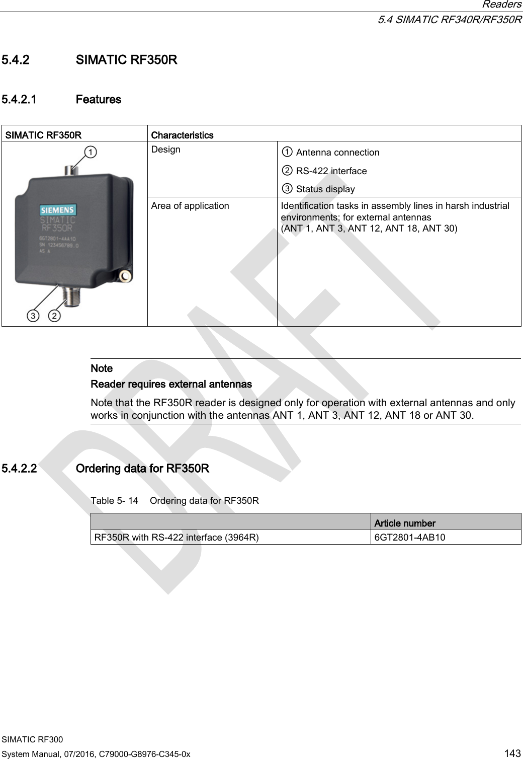
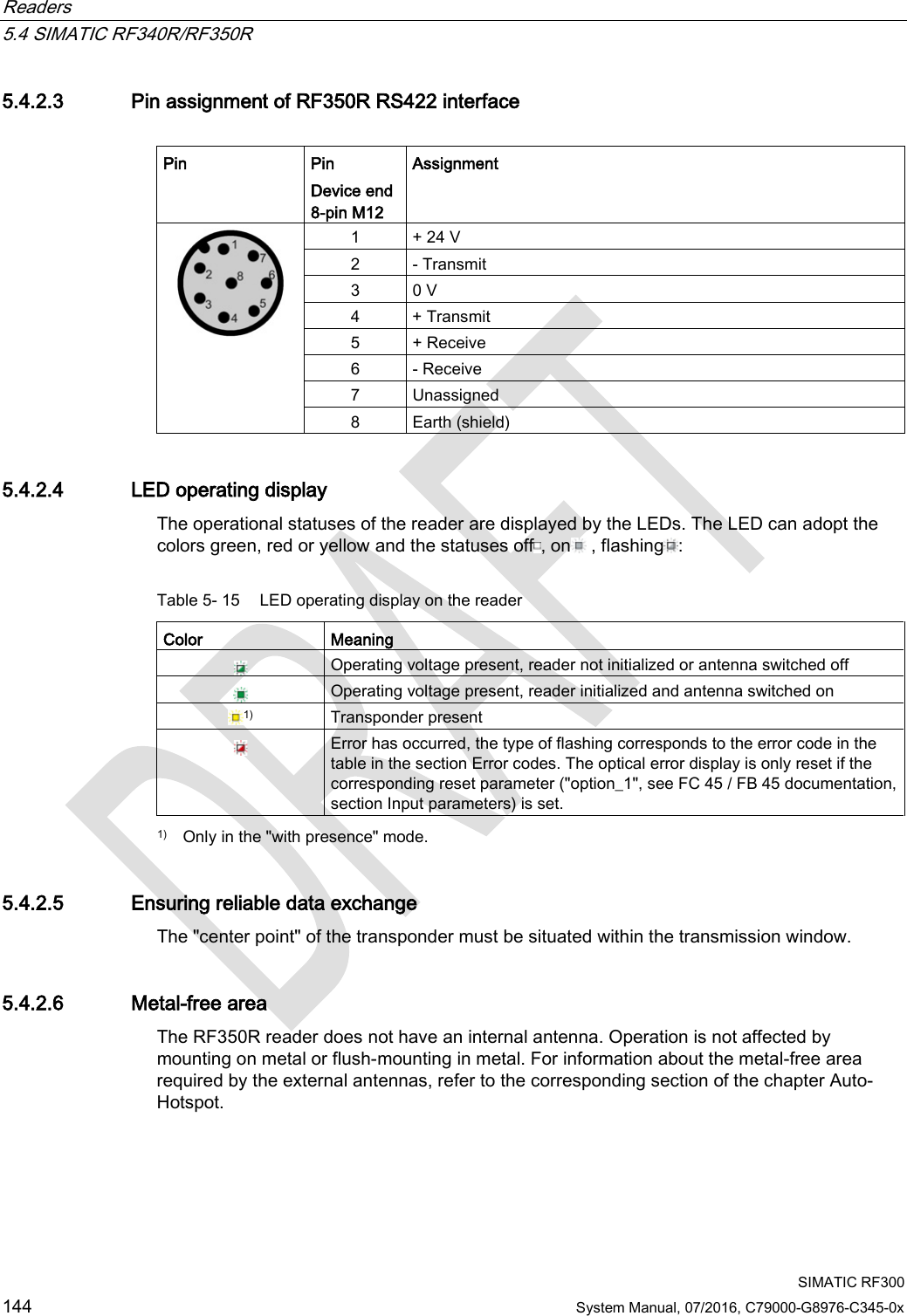
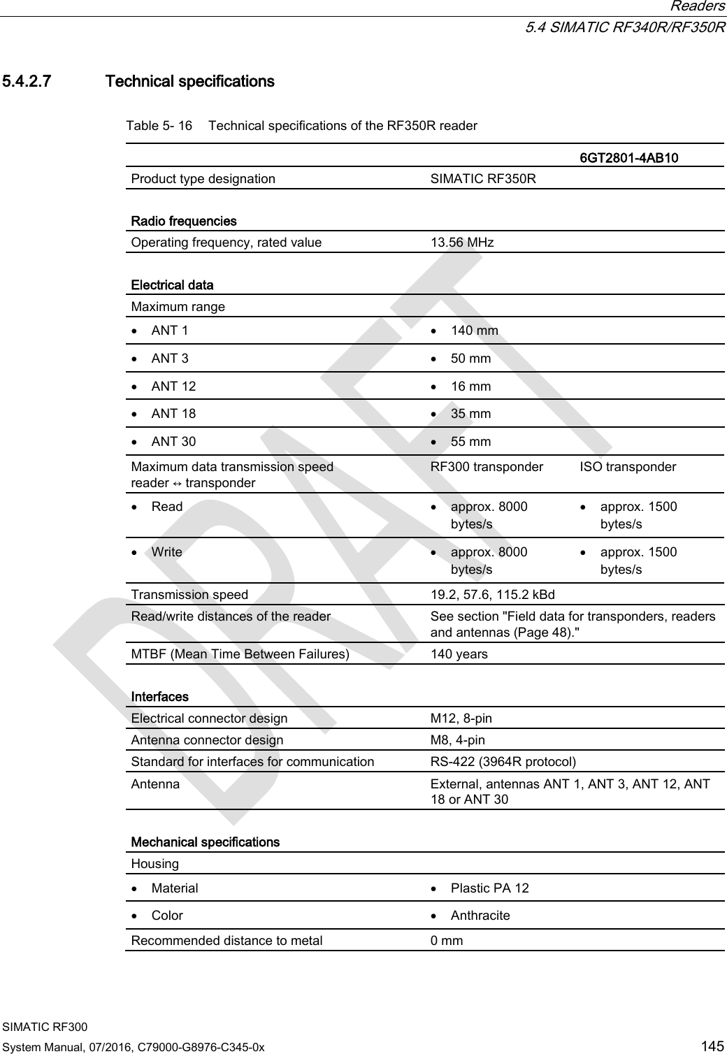

![Readers 5.4 SIMATIC RF340R/RF350R SIMATIC RF300 System Manual, 07/2016, C79000-G8976-C345-0x 149 5.4.3 Use of the reader in hazardous areas TÜV NORD CERT GmbH as accredited test center and certification body, no. 0044 as per Article 9 of the Directive 94/9/EC of the European Council of 23 March 1994, has confirmed the compliance with the essential health and safety requirements relating to the design and construction of equipment and protective systems intended for use in hazardous areas as per Annex II of the Directive. The essential health and safety requirements are satisfied in accordance with the following standards: Document Title EN 60079-0: 2006 Electrical equipment for hazardous gas atmospheres - Part 0: General requirements EN 60079-15: 2005 Electrical equipment for hazardous gas atmospheres - Part 15: Design, testing and identification of electrical equipment with type of protection "n" IEC 61241 -0: 2006 Electrical apparatus for use in the presence of combustible dust - Part 0: General requirements IEC 61241 -1: 2004 Electrical apparatus for use in the presence of combustible dust - Part 1: Protection through enclosure WARNING EXPLOSION HAZARD DO NOT CONNECT OR DISCONNECT EQUIPMENT WHEN A FLAMMABLE OR COMBUSTIBLE ATMOSPHERE IS PRESENT. Identification The identification of the electrical equipment as an enclosed unit is: II 3 G Ex nA nC IIB T5 II 3 D Ex tD A22 IP6x T80 °C -25 °C to +70 °C Un = 20 to 30 VDC The equipment also has the following additional markings: XXXYYYZZZ [= serial number, is assigned during production] TÜV 10 ATEX 556039 [= certificate number]](https://usermanual.wiki/Siemens/RF350R02.Users-manual-2/User-Guide-3127053-Page-37.png)


![Readers 5.6 SIMATIC RF380R SIMATIC RF300 172 System Manual, 07/2016, C79000-G8976-C345-0x 5.6.10 Use of the reader in hazardous areas The TÜV SÜD Automotive GmbH as approved test center as well as the TÜV SÜD Product Service GmbH as certification center, identification number 0123, as per Article 9 of the Directive of the European Council of 23 March 1994 (94/9/EC), has confirmed the compliance with the essential health and safety requirements relating to the design and construction of equipment and protective systems intended for use in hazardous areas as per Annex II of the Directive. The essential health and safety requirements are satisfied in accordance with the following standards: Document Title EN 60079-0: 2006 Electrical equipment for hazardous gas atmospheres - Part 0: General requirements EN 60079-15: 2005 Electrical equipment for hazardous gas atmospheres - Part 15: Design, testing and identification of electrical equipment with type of protection "n" DIN VDE 0848-5: 2001 (in parts) Safety in electrical, magnetic and electromagnetic fields - Part 5: Explosion protection ZLS SK 107.1 Central office of the states for safety; test components Identification The identification of the electrical equipment as an enclosed unit is: II 3G Ex nC IIB T5 -25 °C to +70 °C Um=30Vdc The equipment is assigned the following references: XXXYYYZZZ [= serial number, is assigned during production] TPS 09 ATEX 1 459 X [= certificate number] "No use of the equipment in the vicinity of processes generating high charges" "Do not disconnect plug on load"](https://usermanual.wiki/Siemens/RF350R02.Users-manual-2/User-Guide-3127053-Page-60.png)