Siemens RF350R02 RFID Reader 13.56 MHz User Manual SIMATIC RF300
Siemens AG RFID Reader 13.56 MHz SIMATIC RF300
UserManual.wiki
>
Siemens
>
RF350R02 User Manual
>
Users manual 3
Contents
1.
Users manual 1
2.
Users manual 2
3.
Users manual 3
4.
Users manual 4
5.
Users manual 5
6.
Users manual 1 of 3
7.
Users manual 2 of 3
8.
User manual 3 of 3
Users manual 3
Navigation menu
Upload a User Manual
Namespaces
Wiki Guide
HTML
PDF
Info
Views
User Manual
Discussion / Help
Navigation
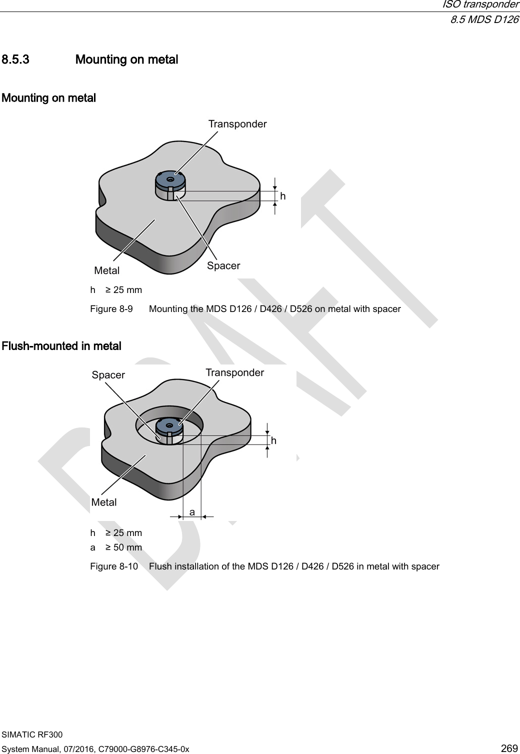
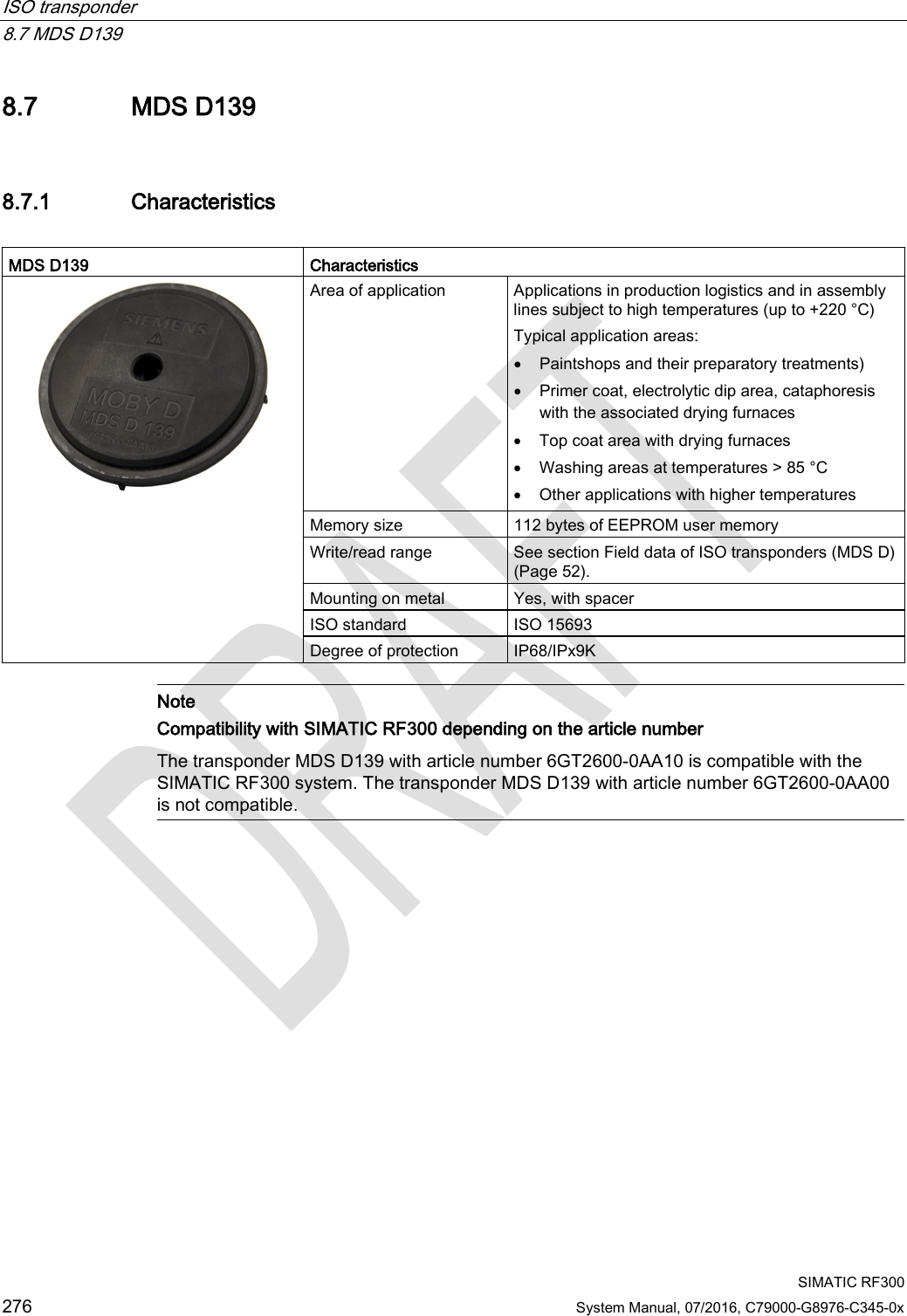
![Antennas 6.5 Minimum distance between antennas SIMATIC RF300 200 System Manual, 07/2016, C79000-G8976-C345-0x 6.5 Minimum distance between antennas Table 6- 3 Minimum distance between antennas Diagram (example) Minimum distance [mm] Antennas next to each other ANT 1 D ≥ 100 mm ANT 3 D ≥ 80 mm ANT 3S D ≥ 20 mm ANT 8 D ≥ 50 mm ANT 12 D ≥ 70 mm ANT 18 D ≥ 100 mm ANT 30 D ≥ 100 mm Antennas face to face ANT 1 D ≥ 500 mm ANT 3 D ≥ 100 mm ANT 3S D ≥ 50 mm ANT 8 D ≥ 50 mm ANT 12 D ≥ 100 mm ANT 18 D ≥ 100 mm ANT 30 D ≥ 200 mm The reader electronics can be mounted directly alongside each other.](https://usermanual.wiki/Siemens/RF350R02.Users-manual-3/User-Guide-3127054-Page-8.png)


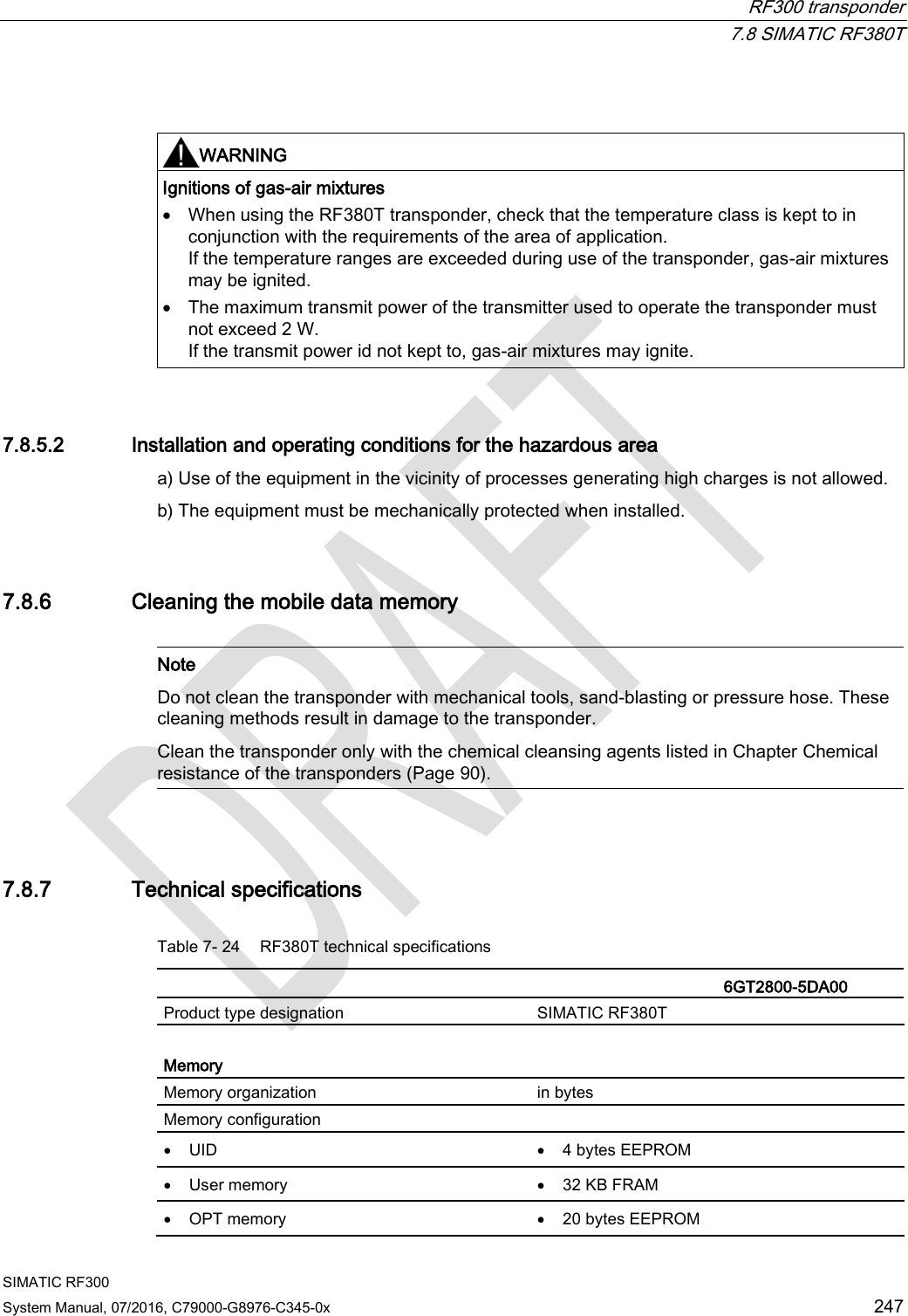
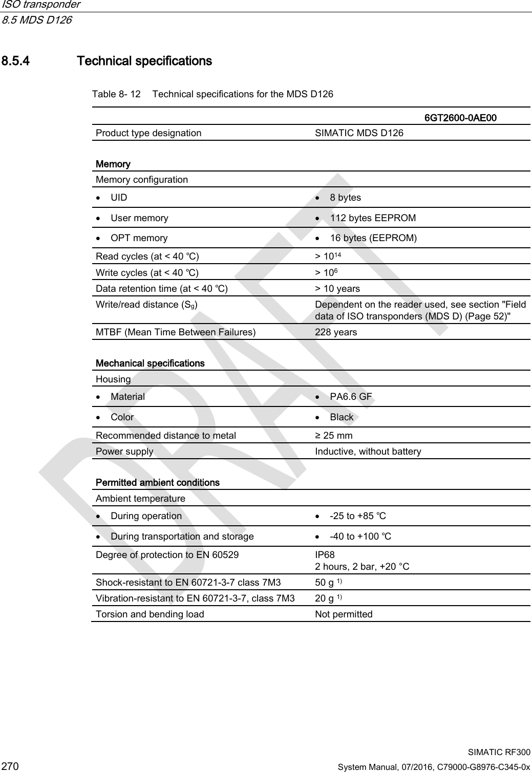
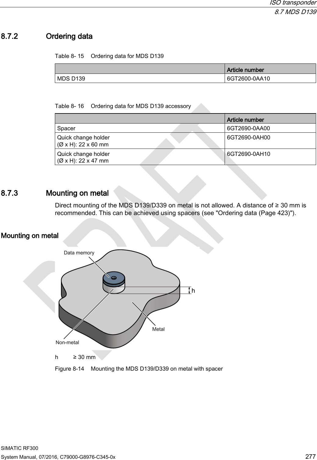
![RF300 transponder 7.8 SIMATIC RF380T SIMATIC RF300 246 System Manual, 07/2016, C79000-G8976-C345-0x 7.8.5 Use of the transponder in the Ex protection area The TÜV SÜD Automotive GmbH as approved test center as well as the TÜV SÜD Product Service GmbH as certification center, identification number 0123, as per Article 9 of the Directive of the European Council of 23 March 1994 (94/9/EC), has confirmed the compliance with the essential health and safety requirements relating to the design and construction of equipment and protective systems intended for use in hazardous areas as per Annex II of the Directive. The essential health and safety requirements are satisfied in accordance with the following standards: Table 7- 22 Approvals Document Title EN 60079-0: 2006 Electrical equipment for hazardous gas atmospheres - Part 0: General requirements EN 60079-15: 2005 Electrical equipment for hazardous gas atmospheres - Part 15: Design, testing and identification of electrical equipment with type of protection "n" DIN VDE 0848-5: 2001 (in parts) Safety in electrical, magnetic and electromagnetic fields - Part 5: Explosion protection ZLS SK 107.1 Central office of the states for safety; test components Identification Table 7- 23 The identification of the electrical equipment as an encapsulated unit II 3G Ex nC IIB T5 -25°C to +70°C Um=30Vdc The equipment is assigned the following references: XXXYYYZZZ [= serial number, is assigned during production] TPS 09 ATEX 1 459 X [= certificate number] "No use of the equipment in the vicinity of processes generating high charges" 7.8.5.1 Use of the transponder in hazardous areas for gases Temperature class delineation for gases The temperature class of the transponder for hazardous areas depends on the ambient temperature range: Ambient temperature range Temperature class -25 °C to +70 °C T5](https://usermanual.wiki/Siemens/RF350R02.Users-manual-3/User-Guide-3127054-Page-54.png)