Siemens RF350R02 RFID Reader 13.56 MHz User Manual SIMATIC RF300
Siemens AG RFID Reader 13.56 MHz SIMATIC RF300
UserManual.wiki
>
Siemens
>
RF350R02 User Manual
>
Users manual 4
Contents
1.
Users manual 1
2.
Users manual 2
3.
Users manual 3
4.
Users manual 4
5.
Users manual 5
6.
Users manual 1 of 3
7.
Users manual 2 of 3
8.
User manual 3 of 3
Users manual 4
Navigation menu
Upload a User Manual
Namespaces
Wiki Guide
HTML
PDF
Info
Views
User Manual
Discussion / Help
Navigation
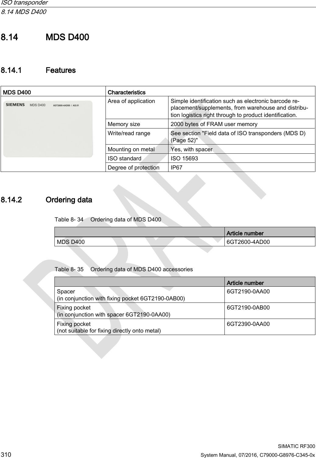


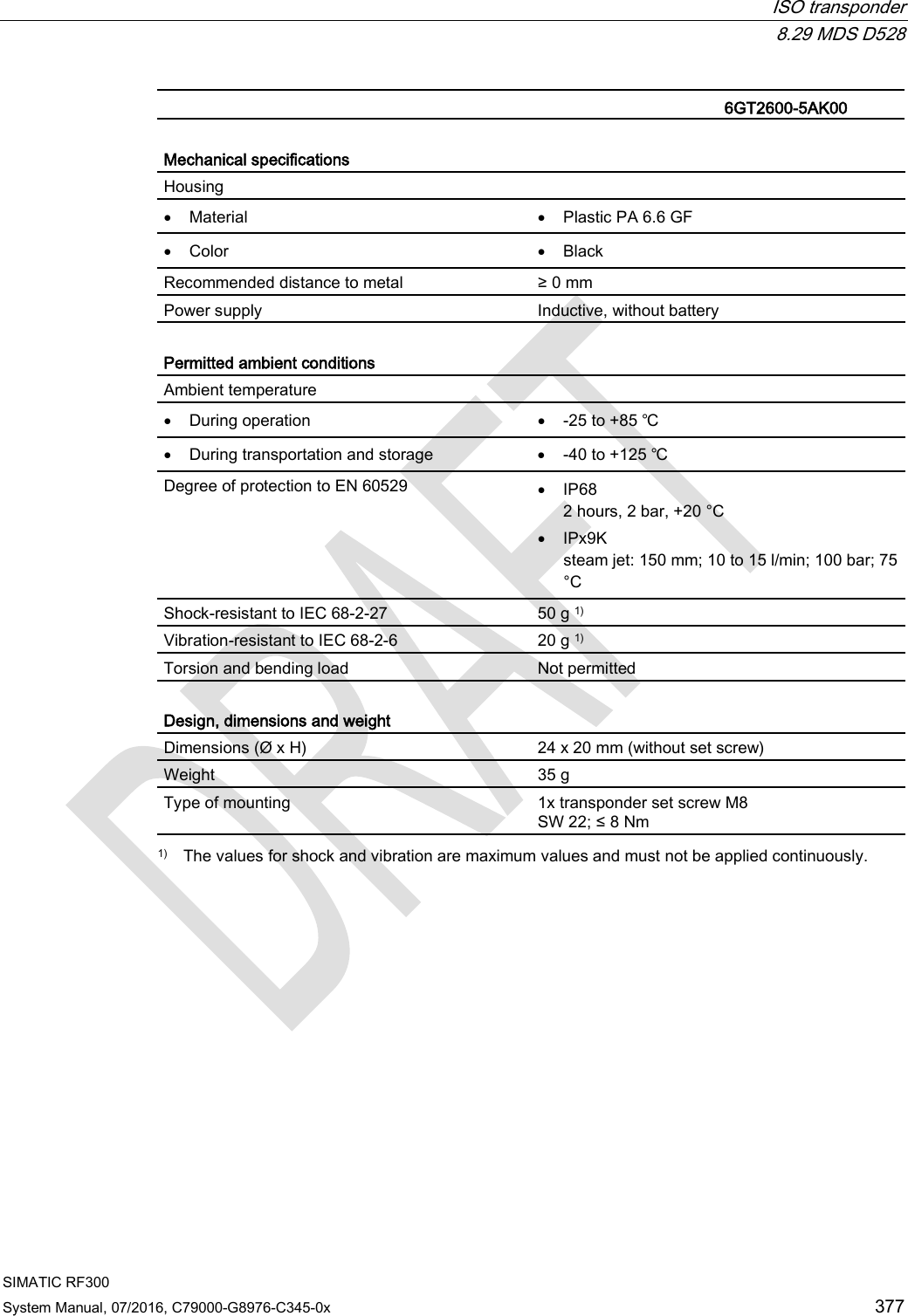
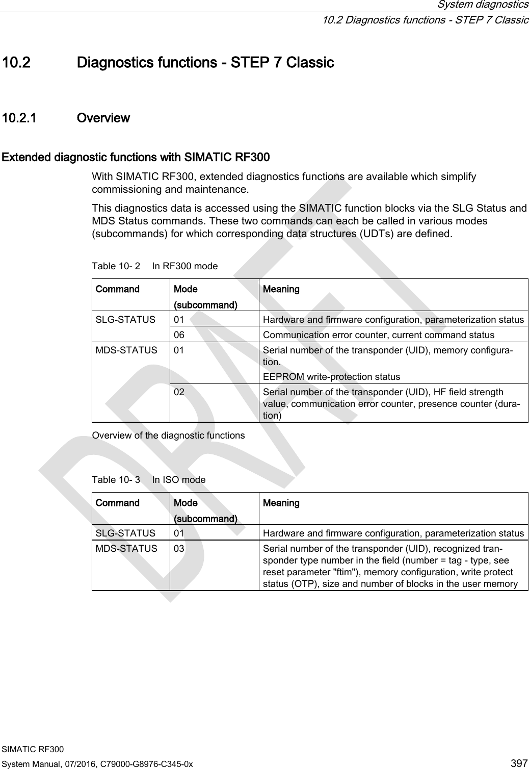
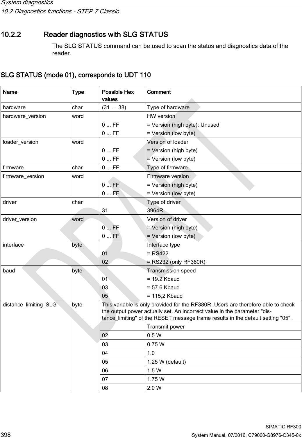
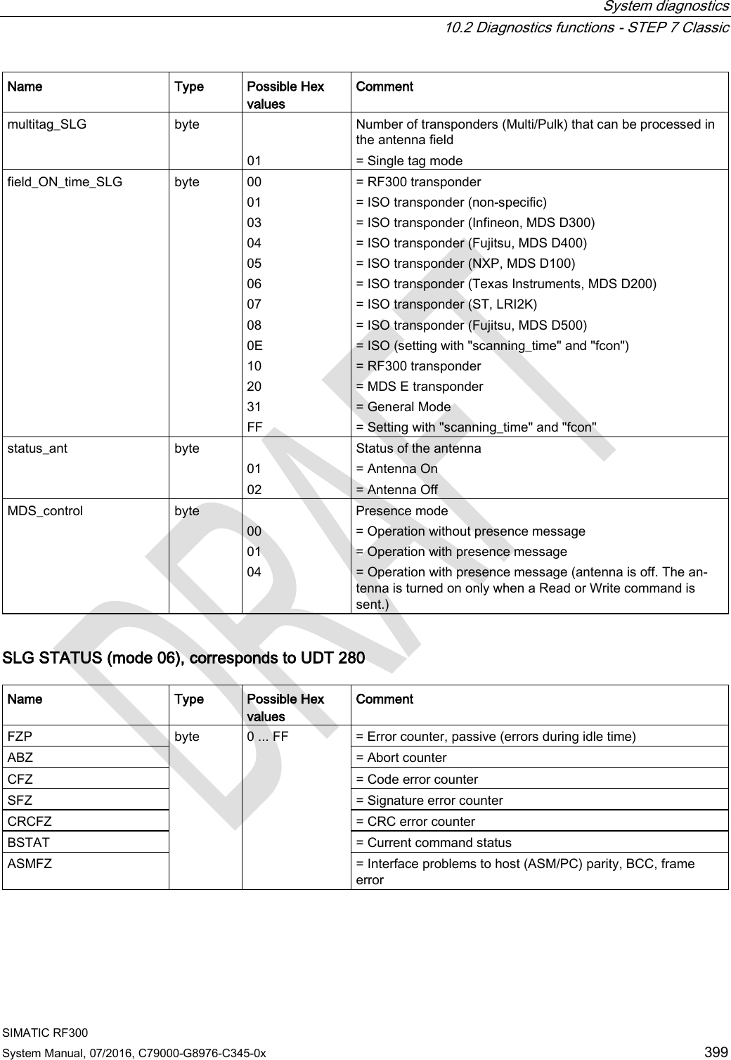
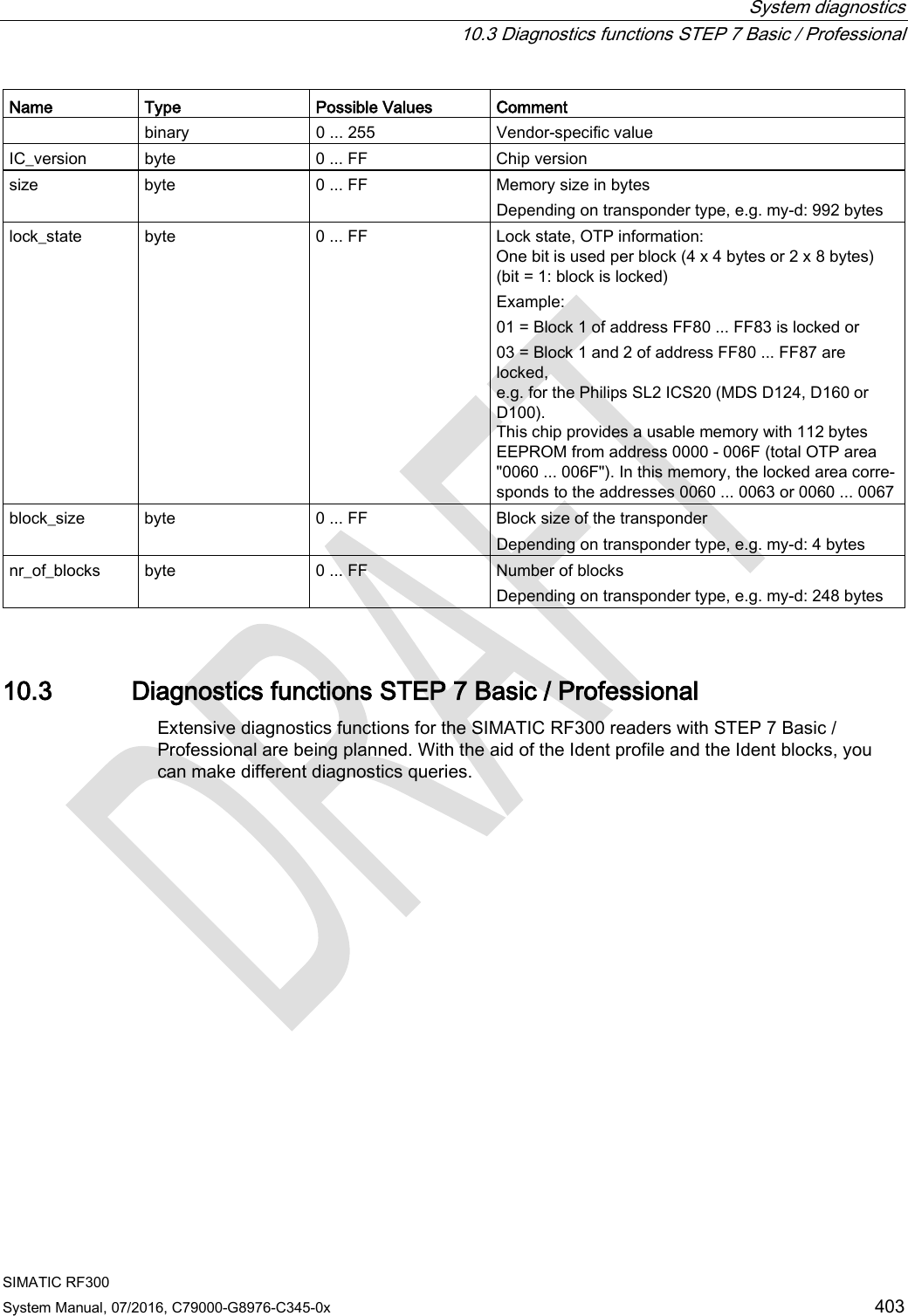
![System diagnostics 10.2 Diagnostics functions - STEP 7 Classic SIMATIC RF300 System Manual, 07/2016, C79000-G8976-C345-0x 401 10.2.3 Transponder diagnostics with MDS STATUS The MDS STATUS command can be used to scan the status and diagnostics data of the transponder that is located within the antenna field. MDS STATUS (mode 1), corresponds to UDT 260 (only for RF300 transponders) Name Type Possible Hex values Comment UID array[1…8] byte 000000005555555 ... 00000000FFFFFFFF Unique identifier = b0-31: 4 byte TAG ID, b32-63: 0 MDS_type byte 01 02 03 04 Transponder memory configuration = Transponder without FRAM = Transponder with FRAM 8 KB = Transponder with FRAM 32 KB = Transponder with FRAM 64 KB Lock_state byte 0 ... FF EEPROM write protection status MDS STATUS (mode 02), corresponds to UDT 270, only for RF300 transponders Name Type Possible Hex values Comment UID array[1…8] byte 0000000055555555 ... 00000000FFFFFFFF Unique identifier = b0-31: 4 byte TAG ID, b32-63: 0 LFD byte 0 ... FF = Value for field strength determined in the transponder FZP byte 0 ... FF = Error counter (passive) ➙ errors during idle time FZA byte 0 ... FF = Error counter (active) ANWZ byte 0 ... FF = Presence counter](https://usermanual.wiki/Siemens/RF350R02.Users-manual-4/User-Guide-3127055-Page-99.png)
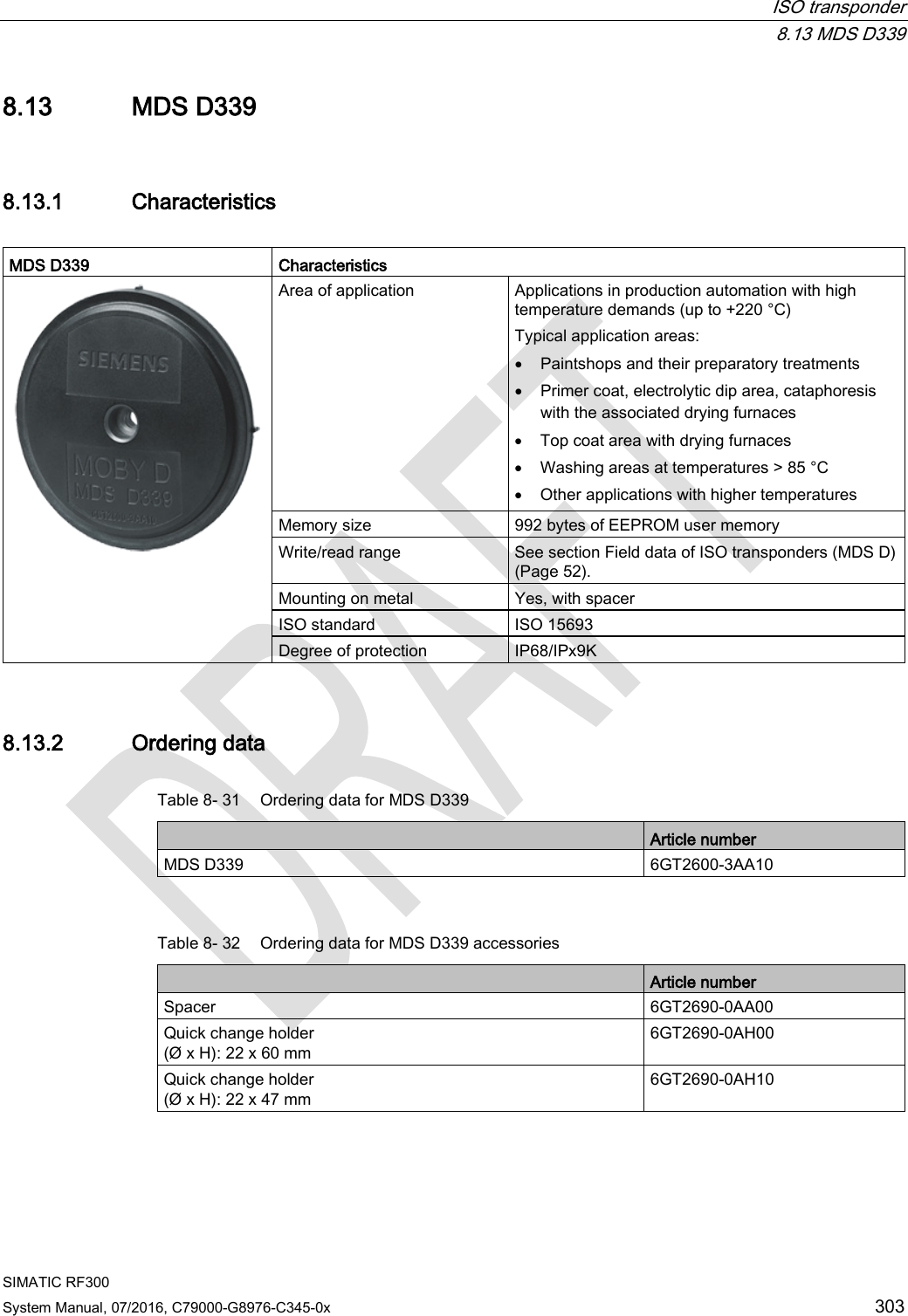
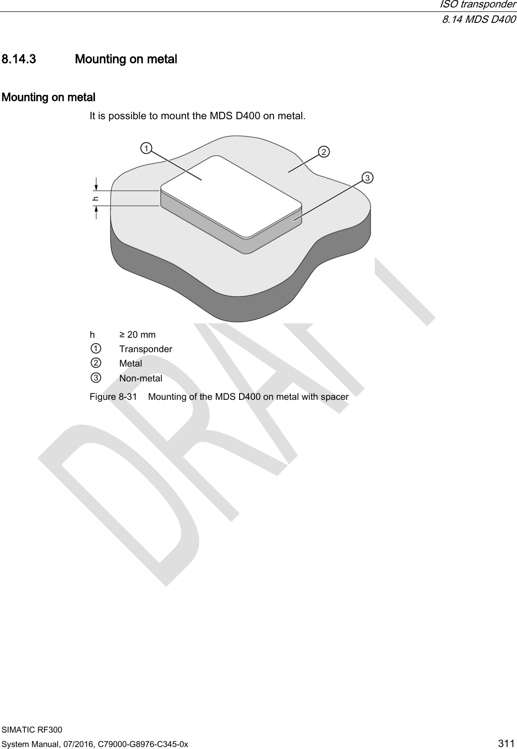
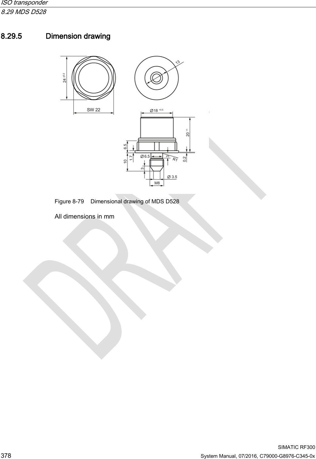
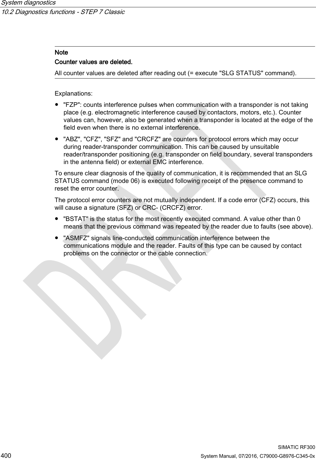
![System diagnostics 10.2 Diagnostics functions - STEP 7 Classic SIMATIC RF300 402 System Manual, 07/2016, C79000-G8976-C345-0x Note Counter values are deleted. All counter values are deleted when the transponder exits the antenna field or when the antenna is switched off. Explanations: ● "LFD" is a measured value for the field strength that is determined in the transponder. The lower the value, the higher the field strength. ● "FZP" counts interference pulses when communication with a transponder is not taking place (e.g. electromagnetic interference caused by contactors, motors, etc.). Counter values can also be generated when a transponder is located at the edge of the field even when there is no external interference. ● "FZA" counts errors that can occur during reader-to-transponder communication. This can be caused by unsuitable reader/transponder positioning (e.g. transponder on field boundary, several data carriers in the field) or external electromagnetic interference. ● "ANWZ" is the value for the time that the transponder remains in the field before the MDS STATUS command (mode 02) is executed. A time step is 10 ms. The maximum time that can be recorded is therefore 2.5 s. MDS STATUS (mode 03), corresponds to UDT 230 Name Type Possible Values Comment UID array[1…8] byte 0000000000000000 ... FFFFFFFFFFFFFFFF Unique identifier =8 byte UID, MSB first MDS_type byte 00 03 04 05 06 07 08 11 12 13 14 15 16 21 22 23 Transponder type (vendor, identification) = ISO transponder (non-specific) = ISO transponder (Infineon, MDS D300) = ISO transponder (Fujitsu, MDS D400) = ISO transponder (Philips, MDS D100) = ISO transponder (Texas Instruments, MDS D200) = ISO transponder (ST, LRI2K) = ISO transponder (Fujitsu, MDS D500) = RF300 transponder (0 kB) = RF300 transponder (8 kB) = RF300 transponder (32 kB) = RF300 transponder (64 kB) = RF300 transponder (128 kB) = RF300 transponder (256 kB) = ISO transponder (NXP, 1 kB, MDS E) = ISO transponder (Infineon, 1 kB, MDS E) = ISO transponder (NXP, 4 kB)](https://usermanual.wiki/Siemens/RF350R02.Users-manual-4/User-Guide-3127055-Page-100.png)