SmartPayTech PAYPLUS PAYMENT INDUSTRIAL PDA User Manual
SmartPayTech INC. PAYMENT INDUSTRIAL PDA Users Manual
UserManual.wiki
>
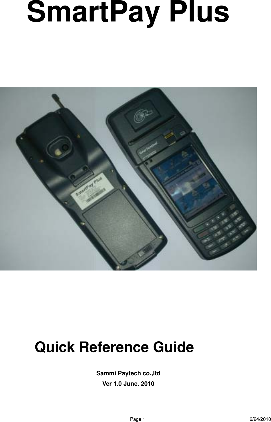
SmartPayTech
>
PAYPLUS User Manual
Users Manual
Navigation menu
Upload a User Manual
Namespaces
Wiki Guide
HTML
PDF
Info
Views
User Manual
Discussion / Help
Navigation

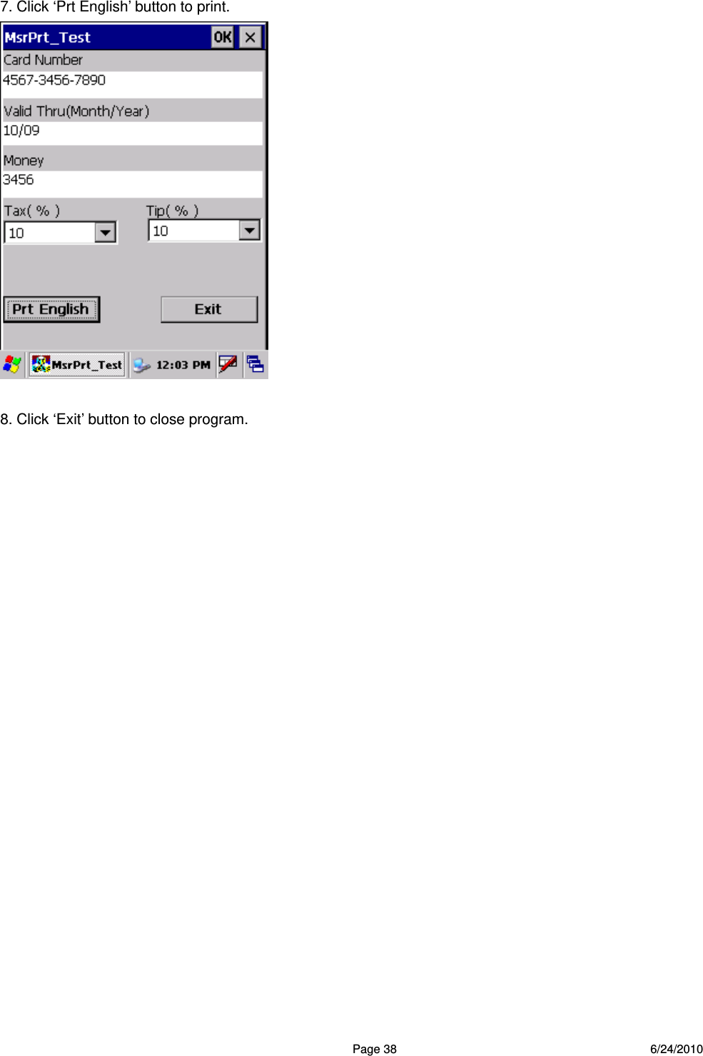
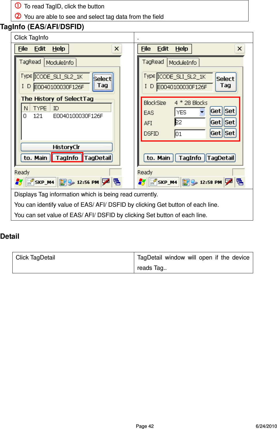
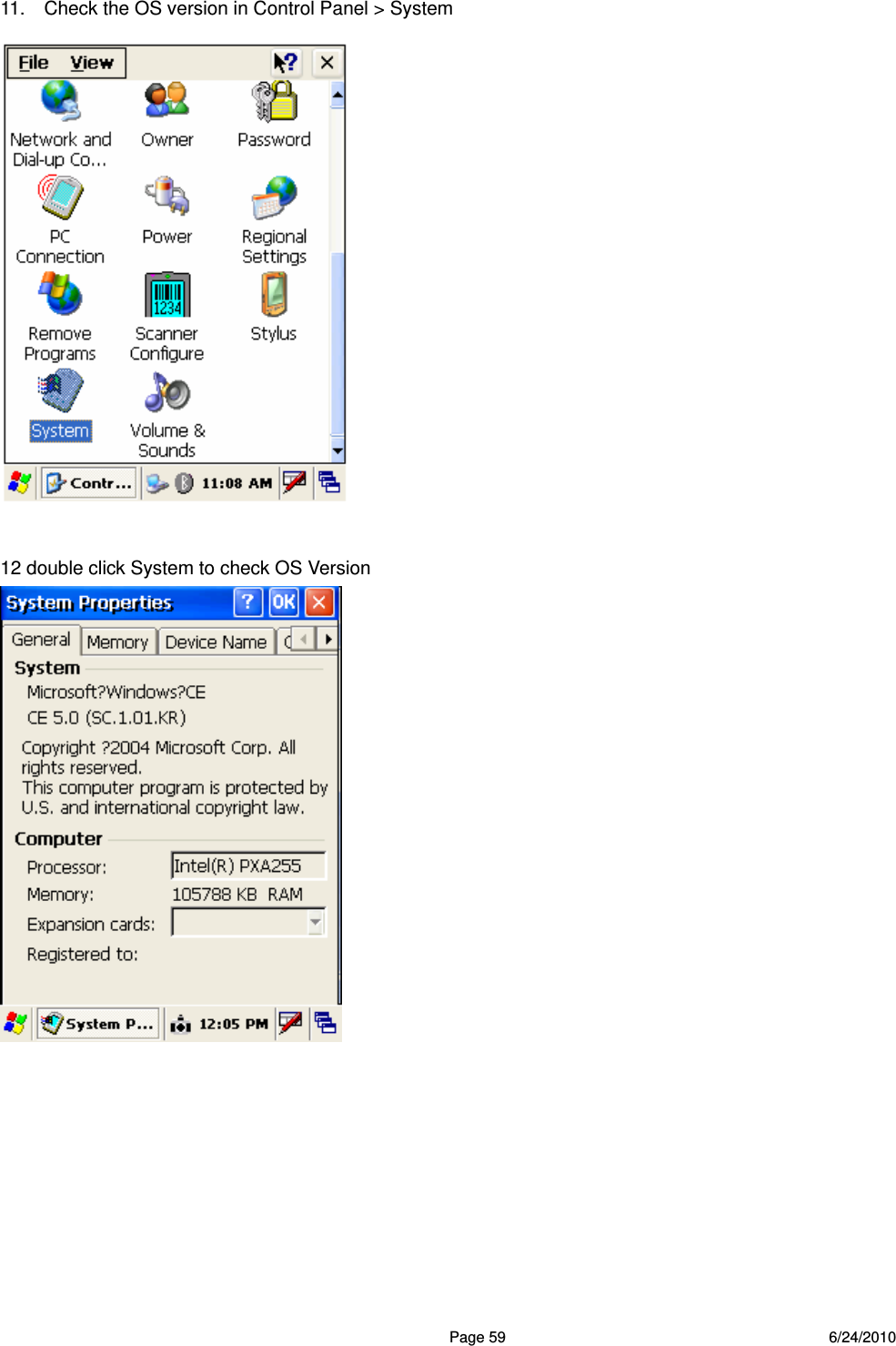
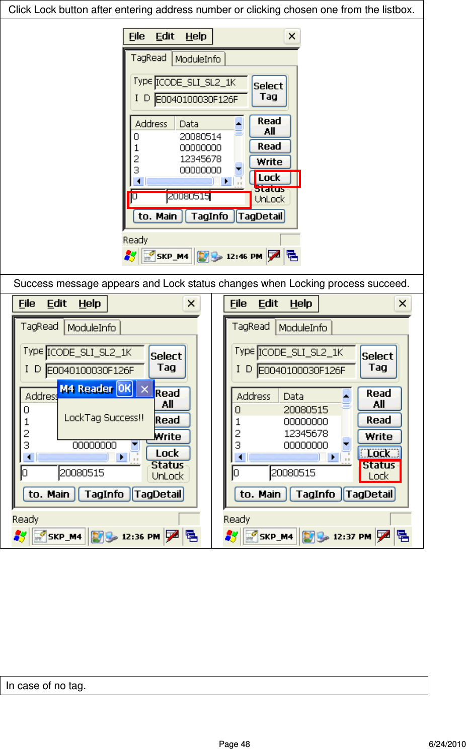
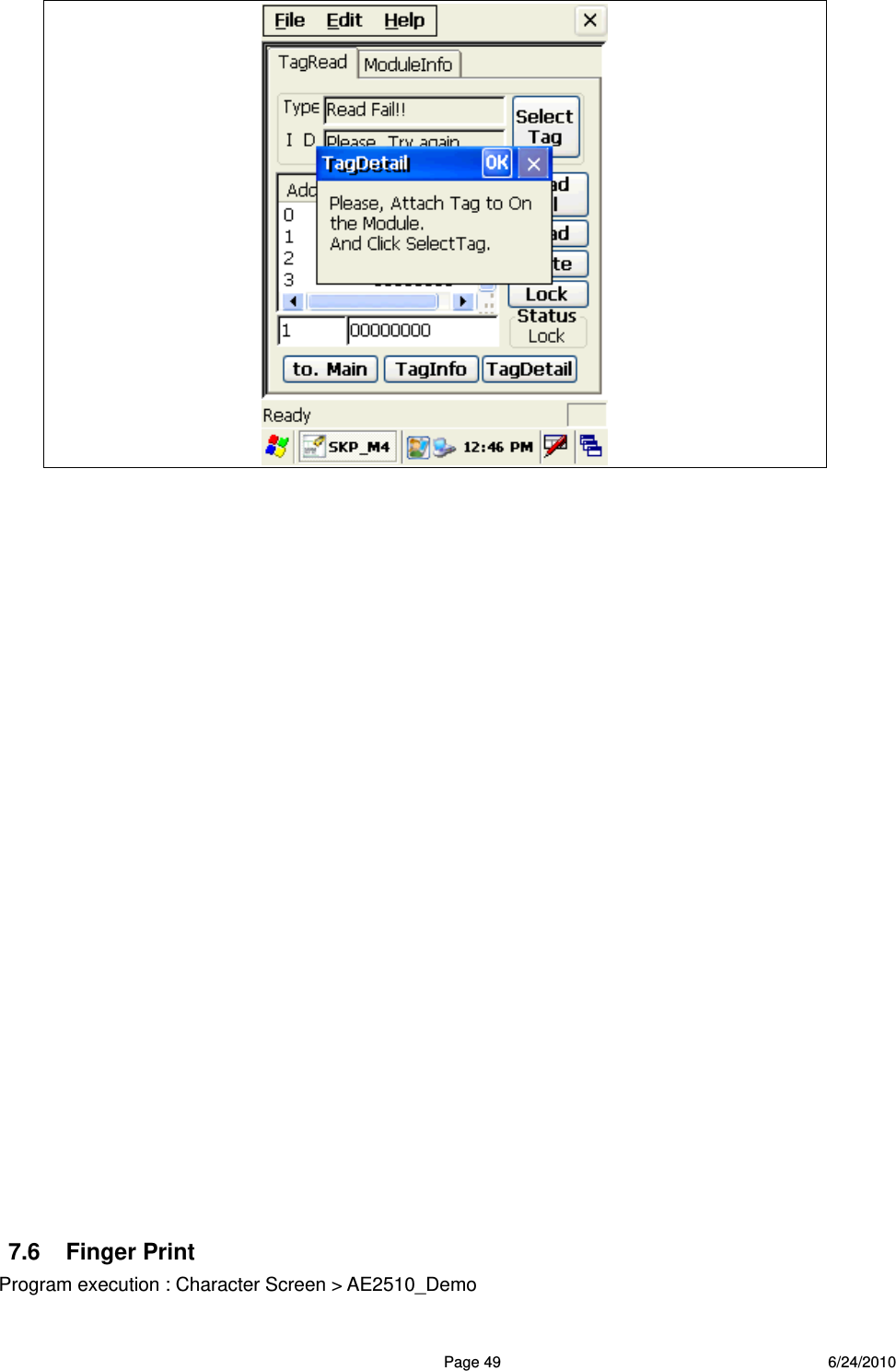
![Page 43 6/24/2010 ReadTagAll commend is automatically executed when TagDetail runs. To read whole memory of the tag To read data of address number which indicated on . Reading address 0 is default if there’s no selection Read data is indicated on To write data to address number which indicated on Refer to data on( digit numbers should be same as once read (To lock data not to be written on TagBlock. (You can see lock status of data on each address. ReadTagAll To read whole memory of the Tag [ReadTagAll] TagDetail Click If success data comes on the list box.. ](https://usermanual.wiki/SmartPayTech/PAYPLUS/User-Guide-1306792-Page-43.png)
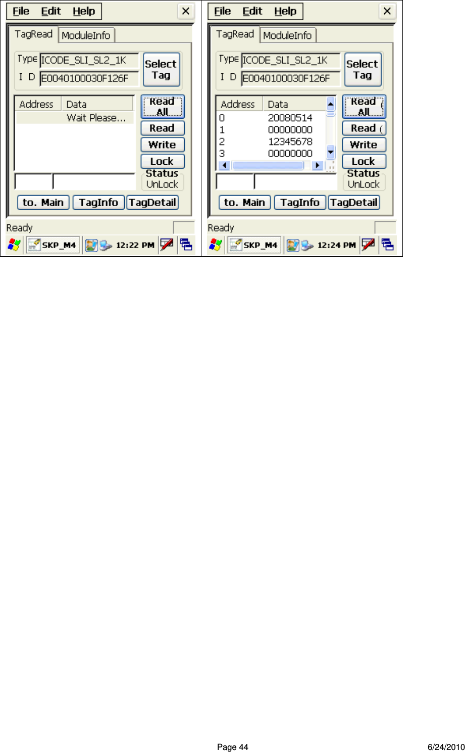
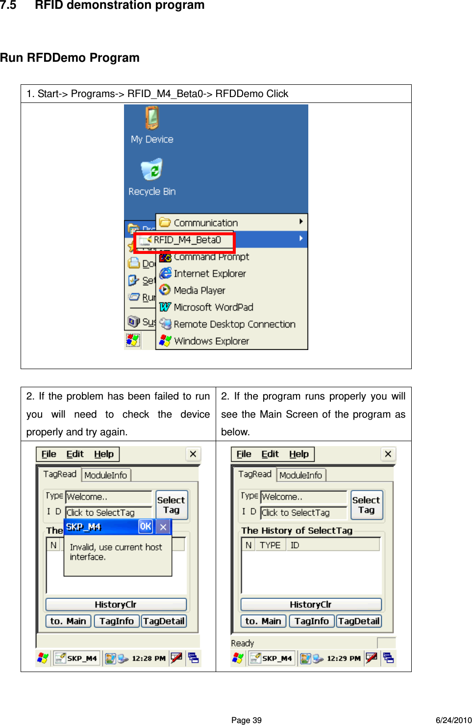
![Page 45 6/24/2010 OneReadTag To check one memory of the address from the tag [OneRead] Enter address number and click Read button. Or select it from ListBox. You’ll see the selected data on the box.](https://usermanual.wiki/SmartPayTech/PAYPLUS/User-Guide-1306792-Page-45.png)
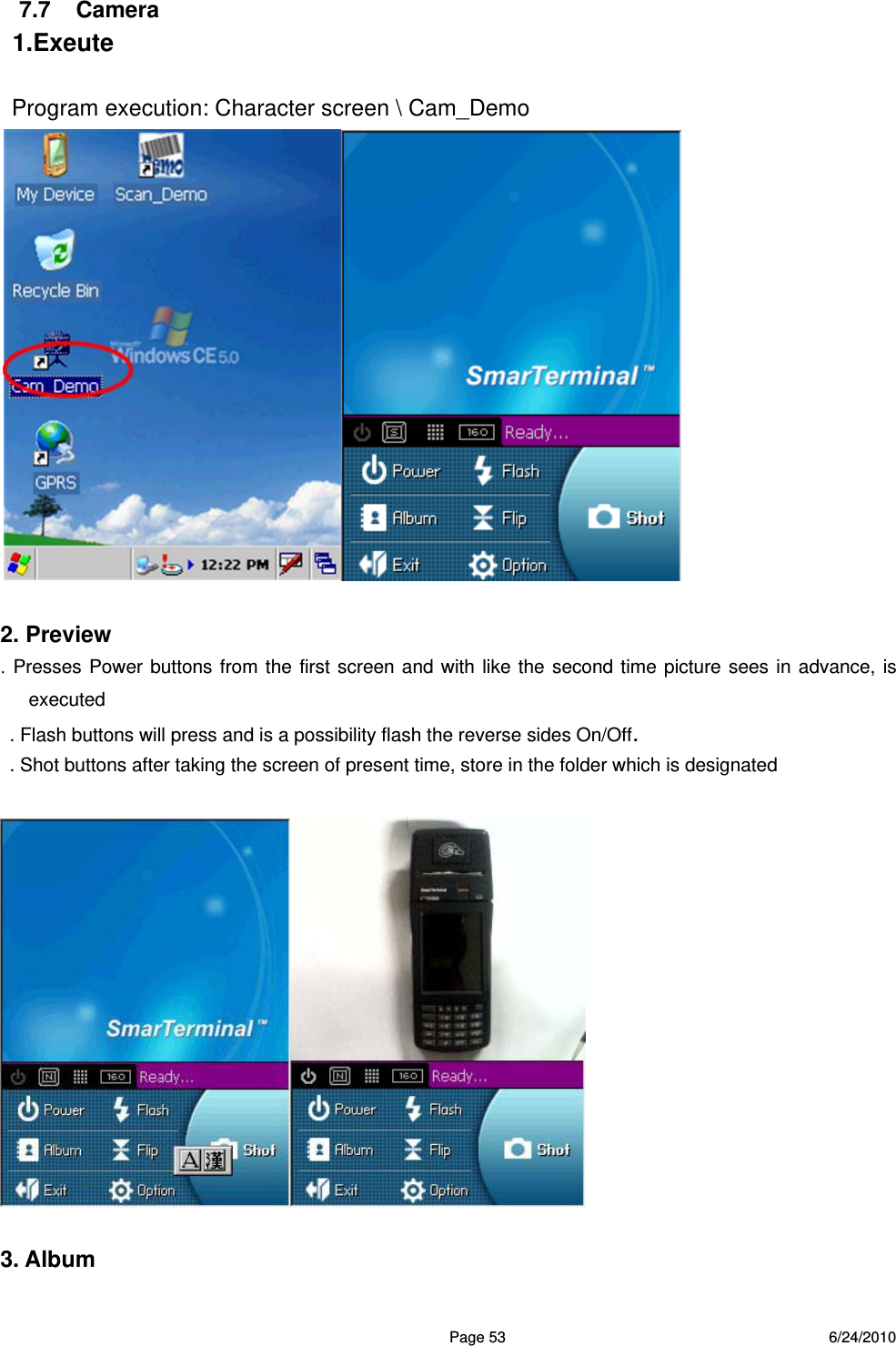
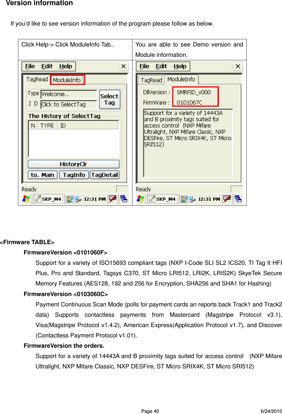
![Page 54 6/24/2010 The third picture will be able to select the format which sees from the album. The second time picture the fact that shows the image and three re-pictures are the screen which list shows the name of file especially from the format which sees. 4. Camera Option The second time picture when pressing Option, is the initial screen. Will select Save Directory and will be able to select the location which will be stored. The location which is set a default is [within system]. The remaining pictures are the items will be able to set this a white balance/picture size etc.](https://usermanual.wiki/SmartPayTech/PAYPLUS/User-Guide-1306792-Page-54.png)