Sony S480C Sony Remote Card System Reader/Writer User Manual
Sony Corporation Sony Remote Card System Reader/Writer
UserManual.wiki
>
Sony
>
S480C User Manual
User Manual
Navigation menu
Upload a User Manual
Namespaces
Wiki Guide
HTML
PDF
Info
Views
User Manual
Discussion / Help
Navigation
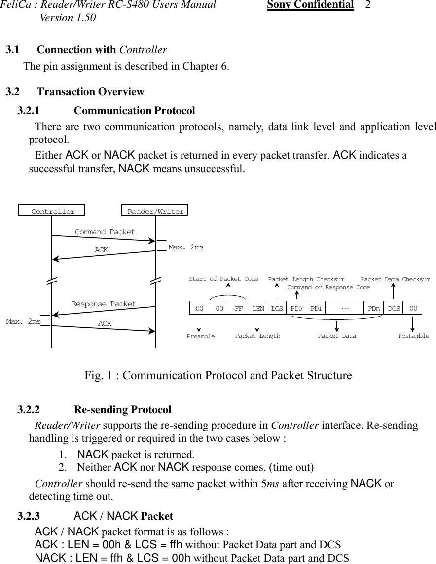
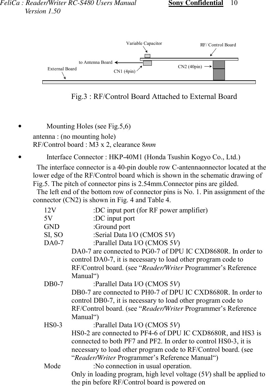
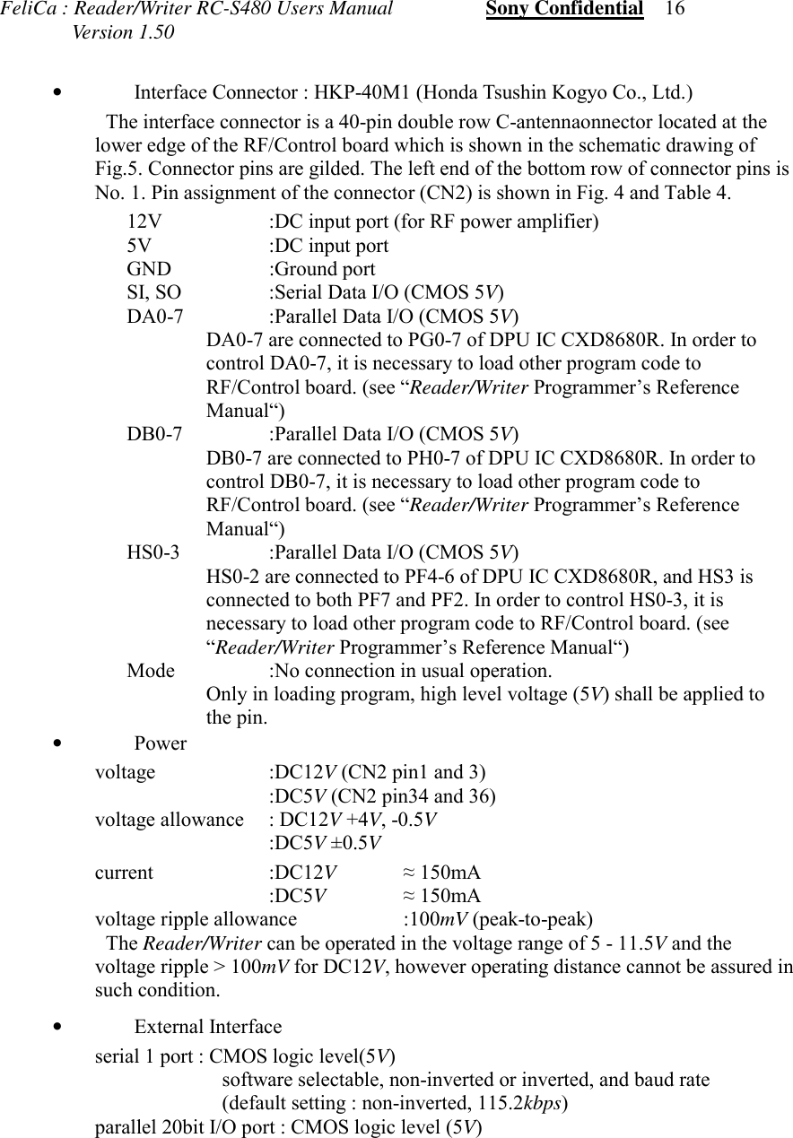
![FeliCa : Reader/Writer RC-S480 Users Manual Sony Confidential 11 Version 1.50 Fig.4 : Pin Assignment of Connectors CN1-2Pin No. Pin Assignment Pin Assignment Pin No.1 12V No Connection 23 12V No Connection 45 No Connection GND 67 No Connection GND 89 DA0 SI 1011 DA1 SO 1213 DA2 No Connection 1415 DA3 MODE 1617 DA4 DB0 1819 DA5 DB1 2021 DA6 DB2 2223 DA7 DB3 2425 HS0 DB4 2627 HS1 DB5 2829 HS2 DB6 3031 HS3 DB7 3233 No Connection 5V 3435 No Connection 5V 3637 GND No Connection 3839 GND No Connection 40Table 4 : Pin Assignment of Interface Connector CN2Modu., Demodu. & Power Amp.*R/WRD*WDGND5VCARRIER*CARRIER12VRFIN+RFIN-RFOUT+RFOUT-EN/*INHController*WD*R/WCARRIER*CARRIEREN/*INHRD SISOMODEDA[0-7]DB[0-7]HS[0-3]GND5Vto AntennaHS[0-3]DA[0-7]SI12VSO12VGNDGNDGNDHS0HS3HS1HS25V5VGNDDA3DA1DA0DA4DA6DA2DA7DA5MODEDB2DB4DB7DB[0-7]DB0DB3DB6DB1DB5CN11234CN2CON40A13579111315171921232527293133353739246810121416182022242628303234363840](https://usermanual.wiki/Sony/S480C/User-Guide-86124-Page-14.png)