Southern Avionics SD100 Non Directional Radiobeacon (NDB) User Manual fcc short
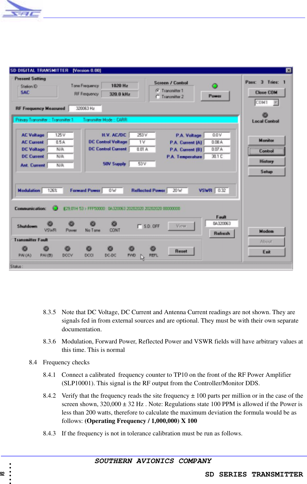
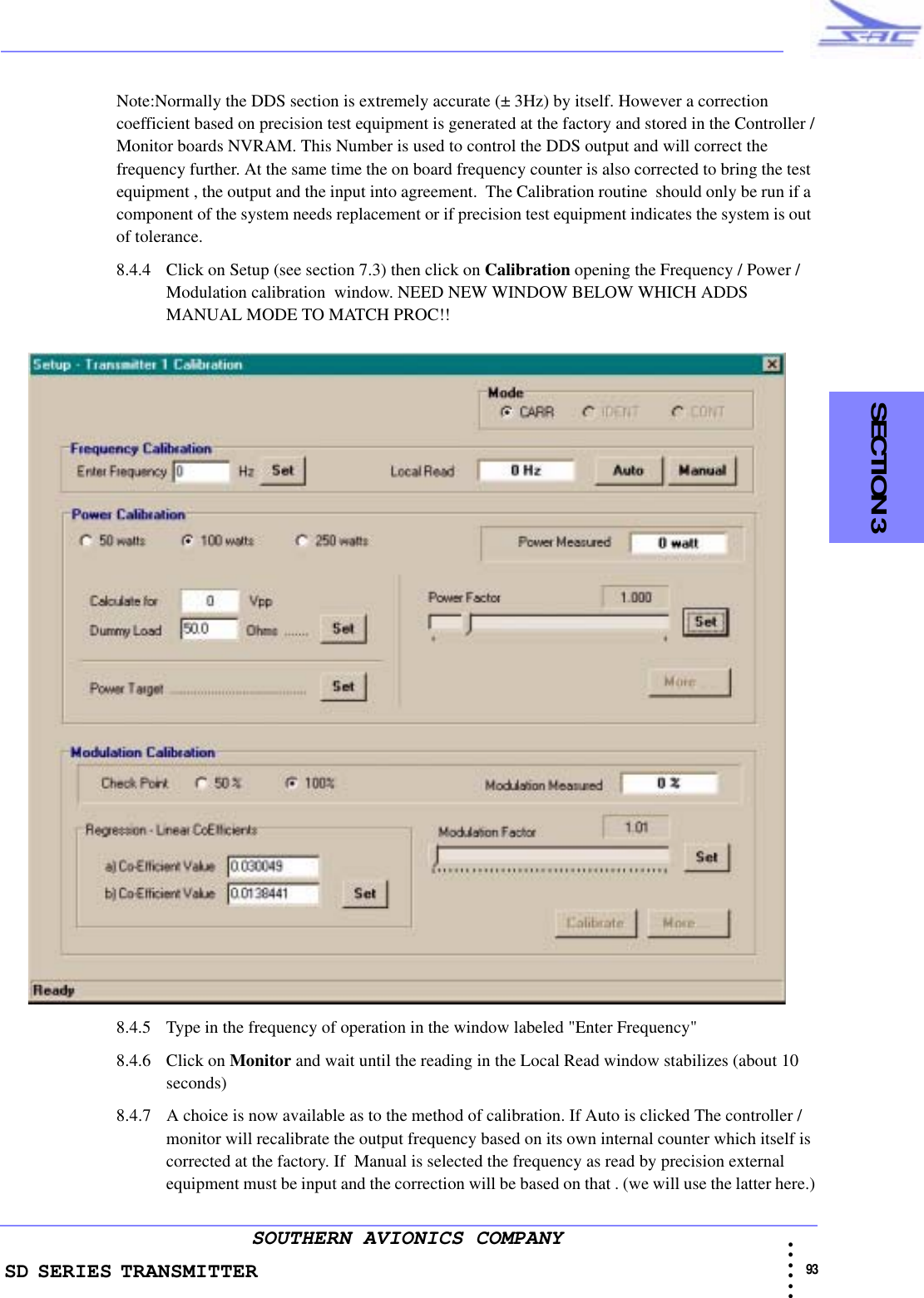
Southern Avionics Company Non Directional Radiobeacon (NDB) fcc short
UserManual.wiki
>
Southern Avionics
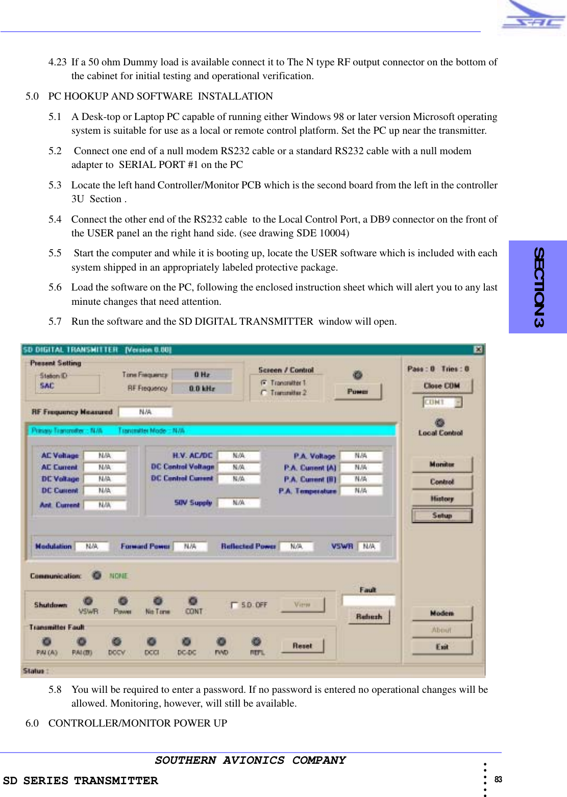
>
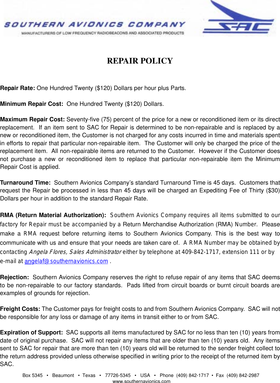
SD100 User Manual
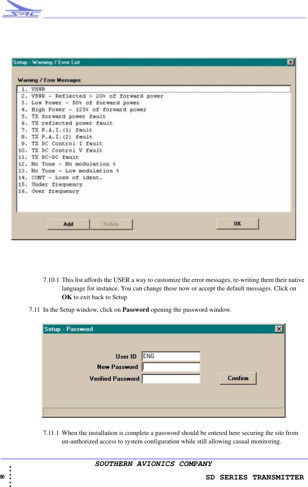
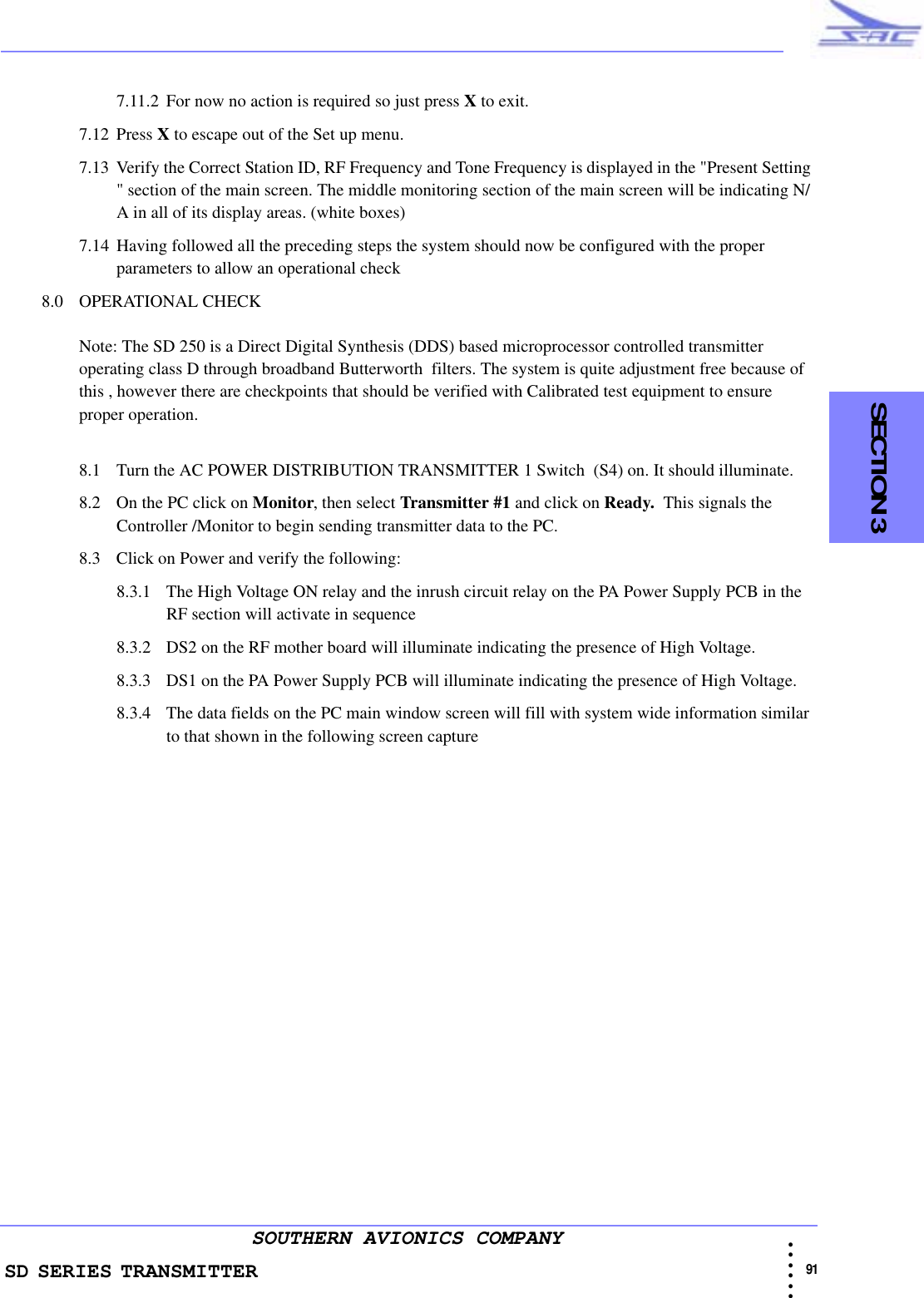
SD100 Manual
Navigation menu
Upload a User Manual
Namespaces
Wiki Guide
HTML
PDF
Info
Views
User Manual
Discussion / Help
Navigation