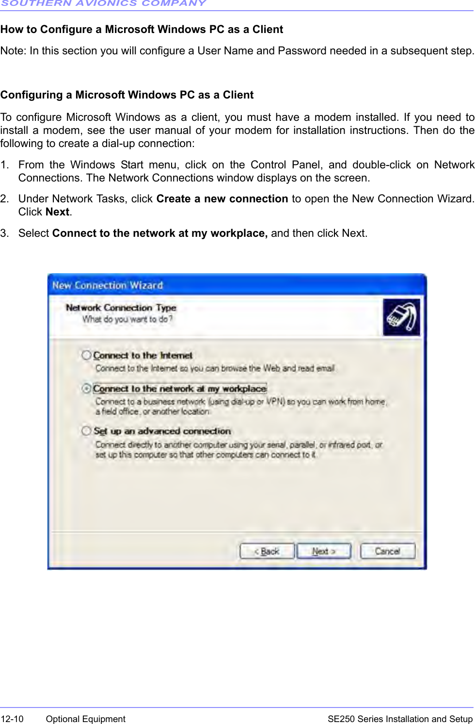
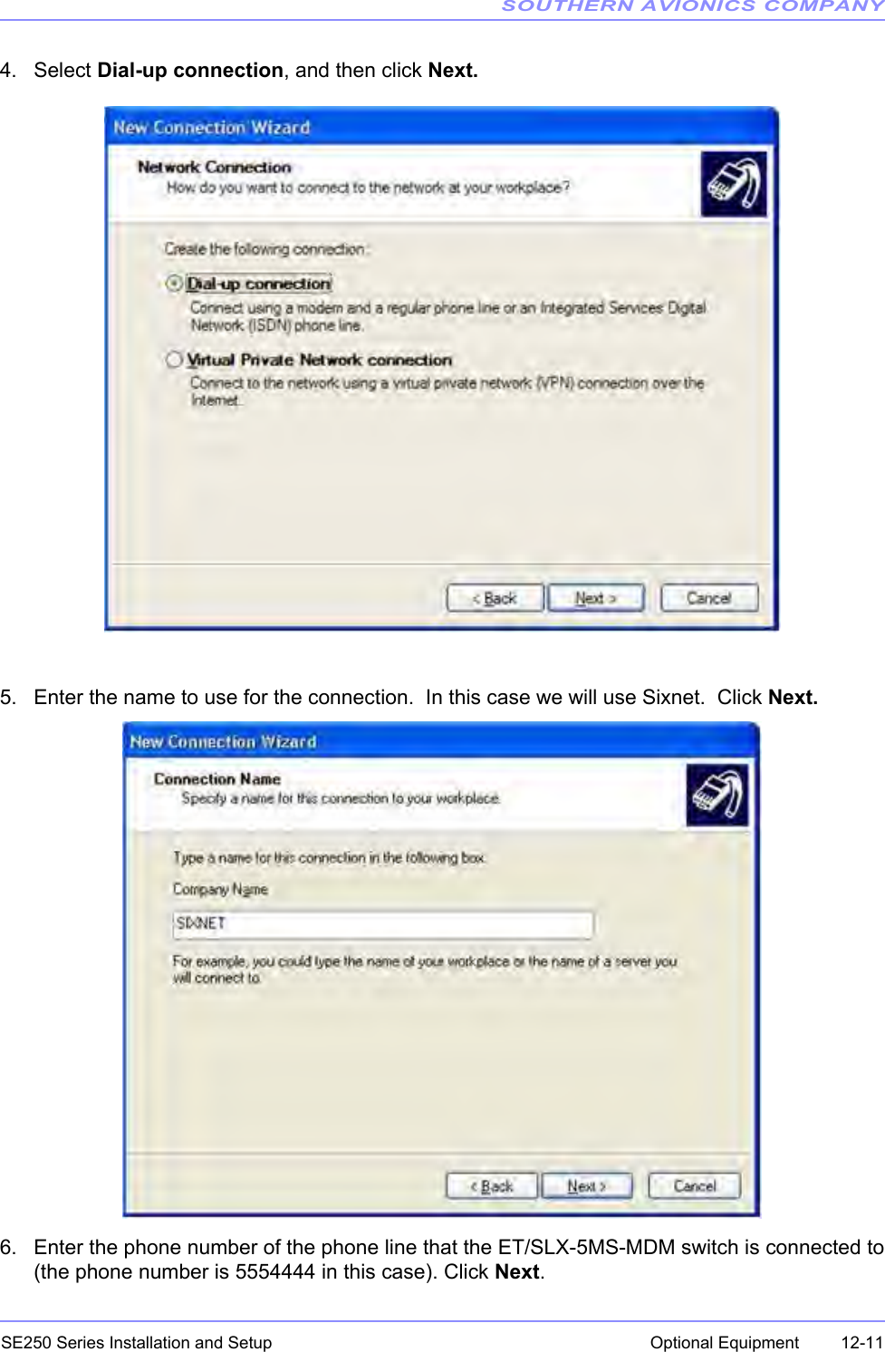
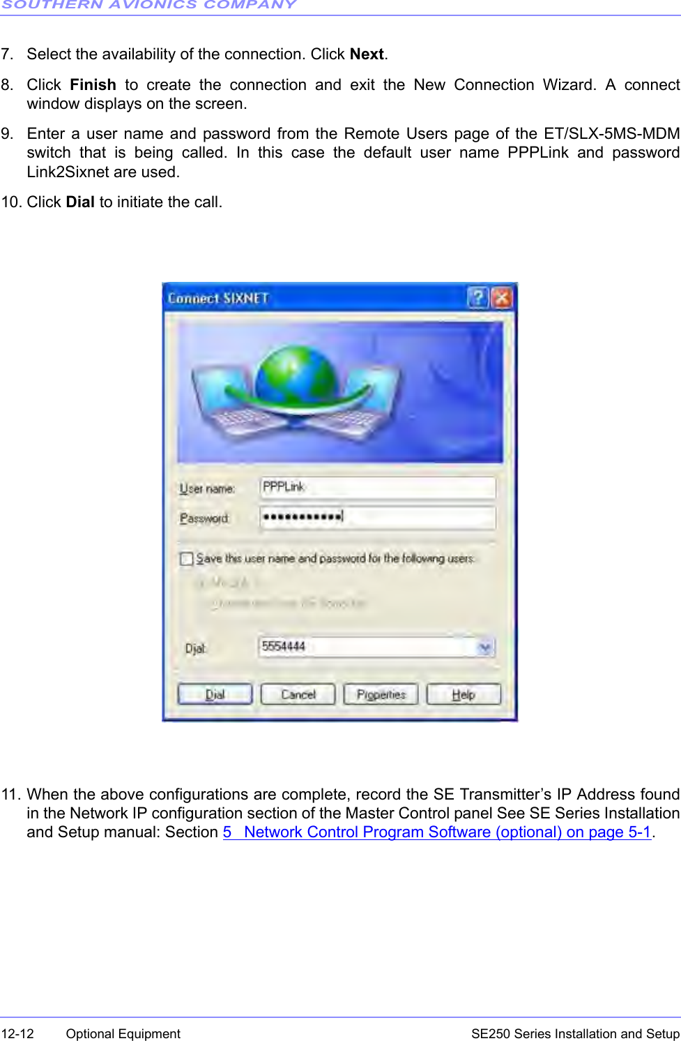
Southern Avionics SE250 Non-Directional Beacon User Manual SE250 Installation and Setup
Southern Avionics Company Non-Directional Beacon SE250 Installation and Setup
UserManual.wiki
>
Southern Avionics
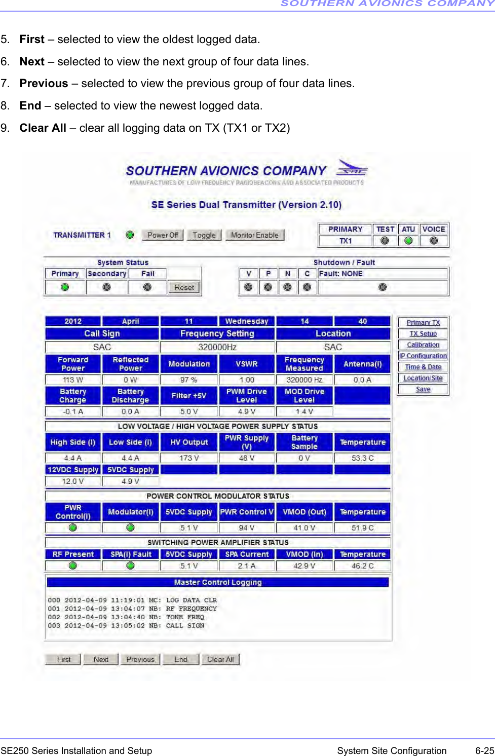
>
SE250 User Manual
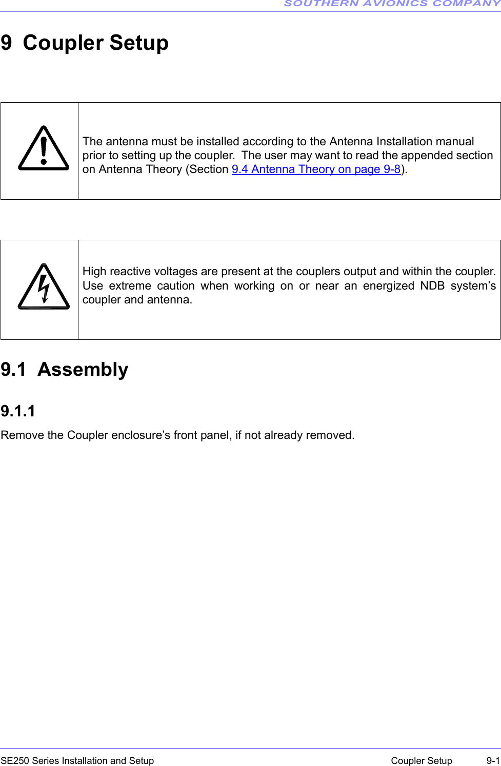
SE250 Installation and Setup Manual
Navigation menu
Upload a User Manual
Namespaces
Wiki Guide
HTML
PDF
Info
Views
User Manual
Discussion / Help
Navigation

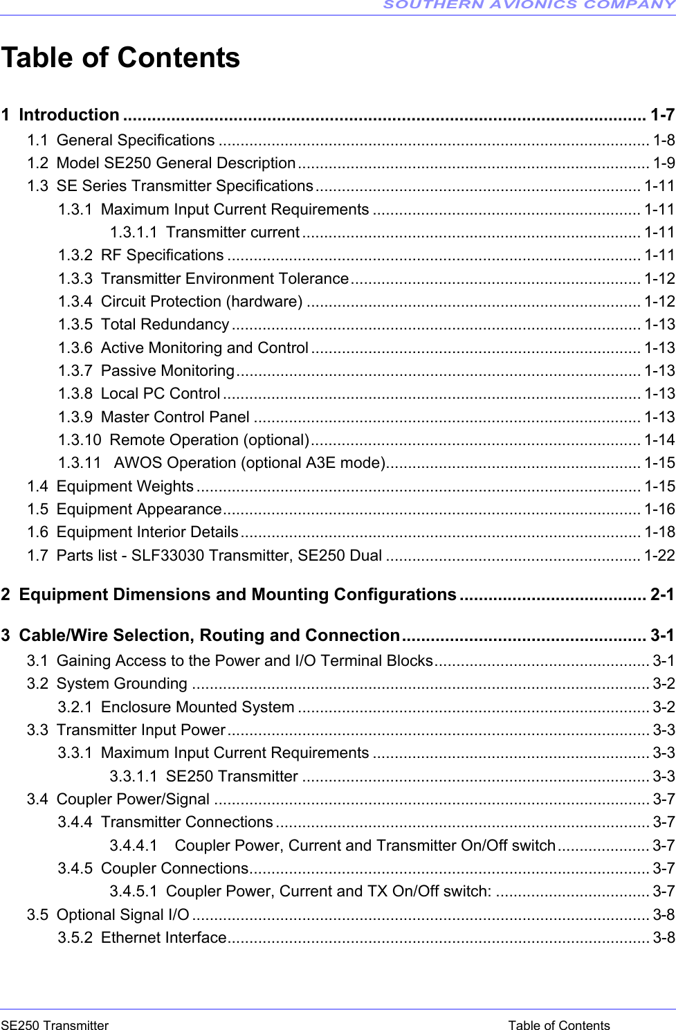
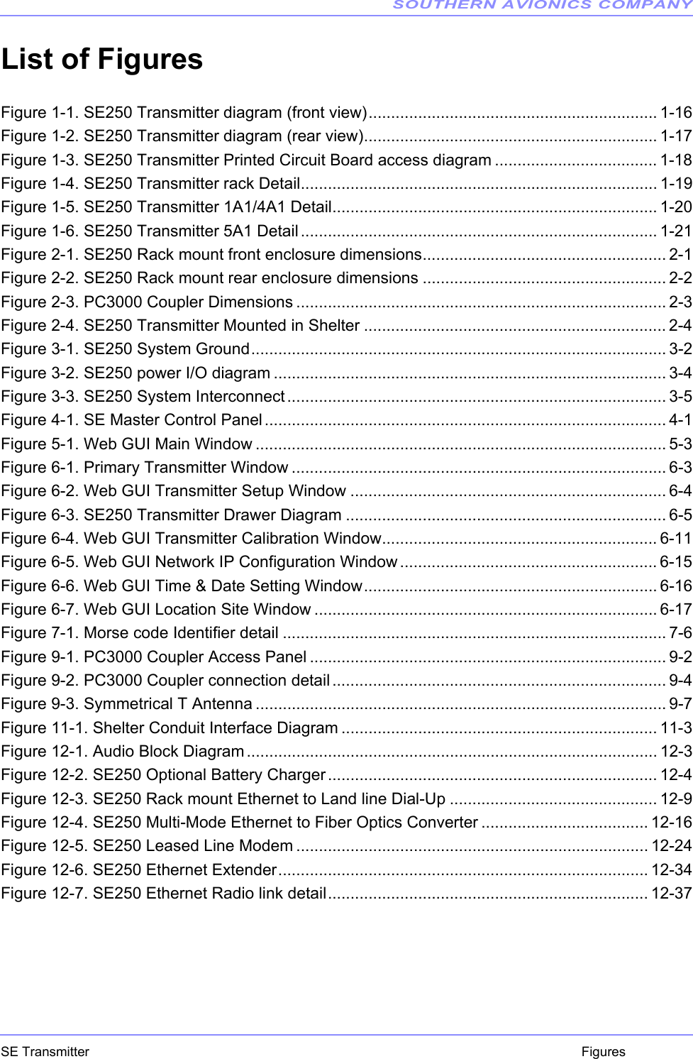


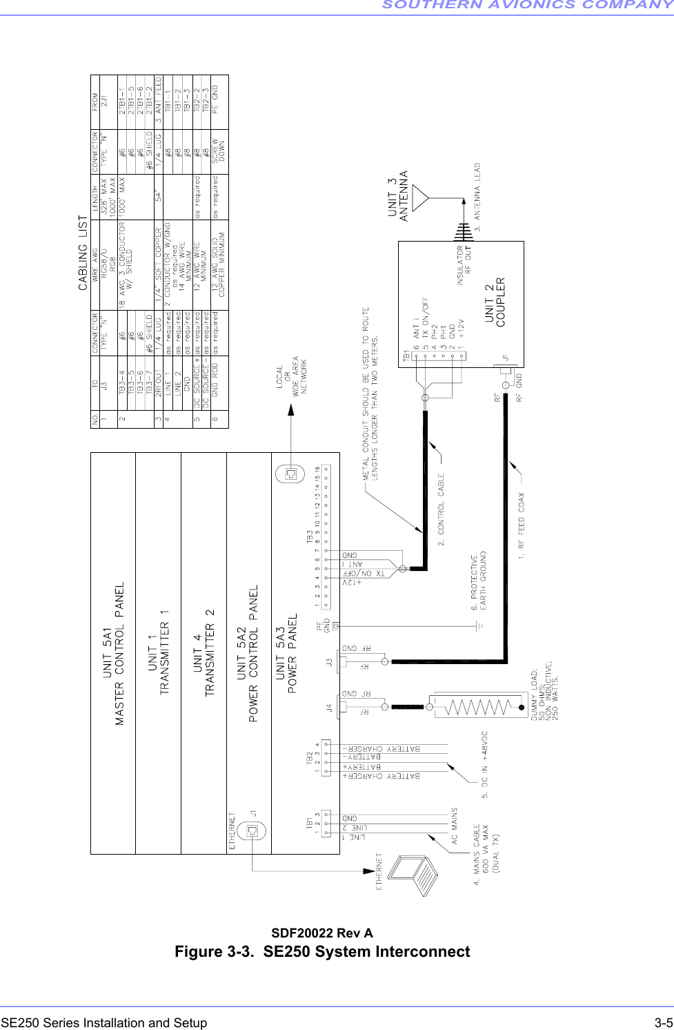
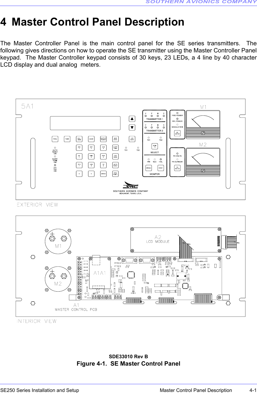
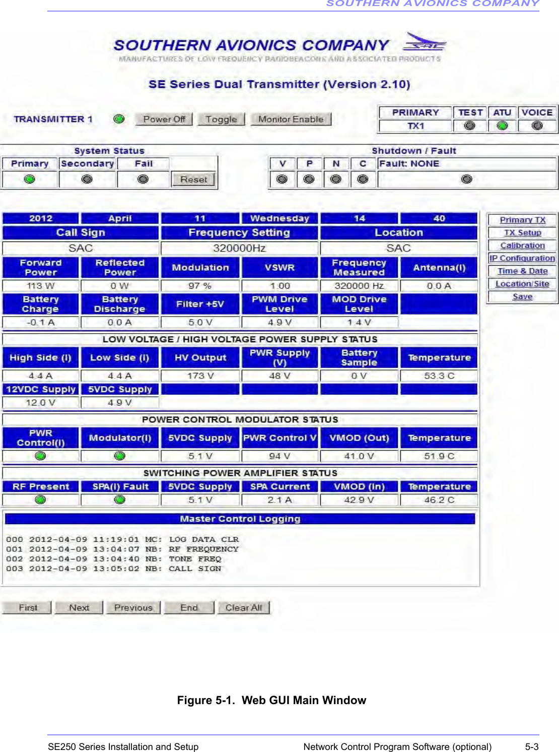
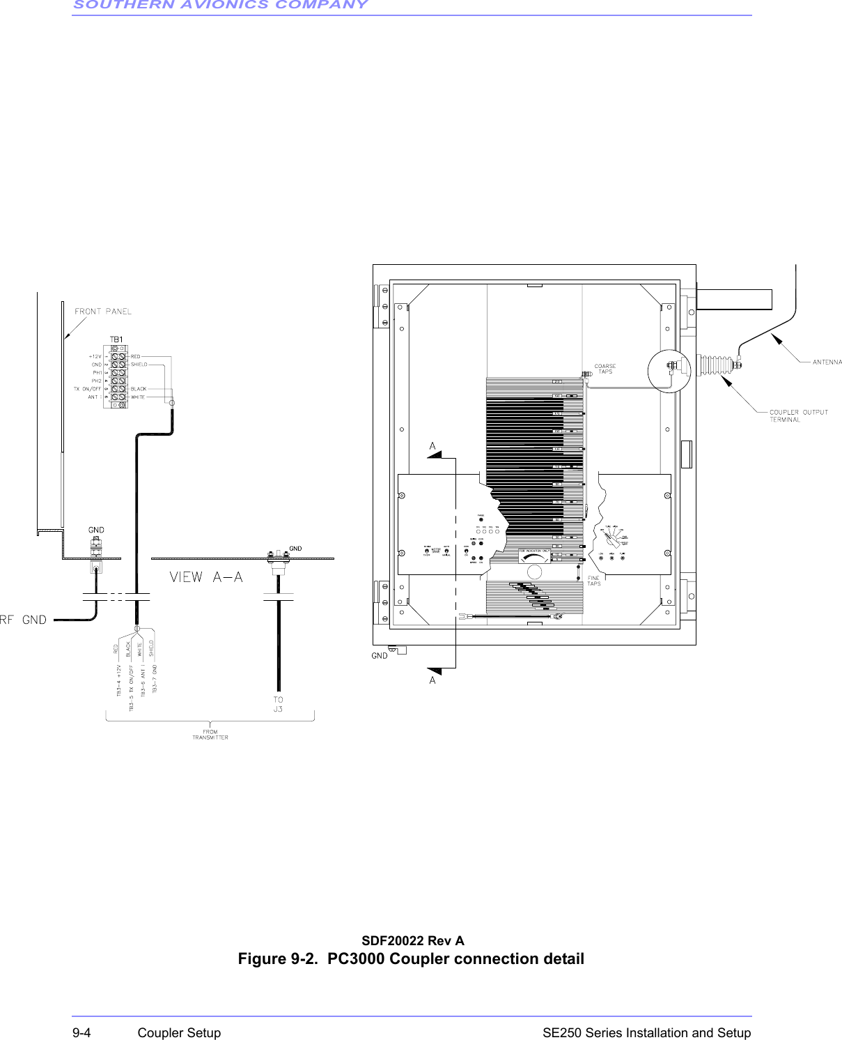
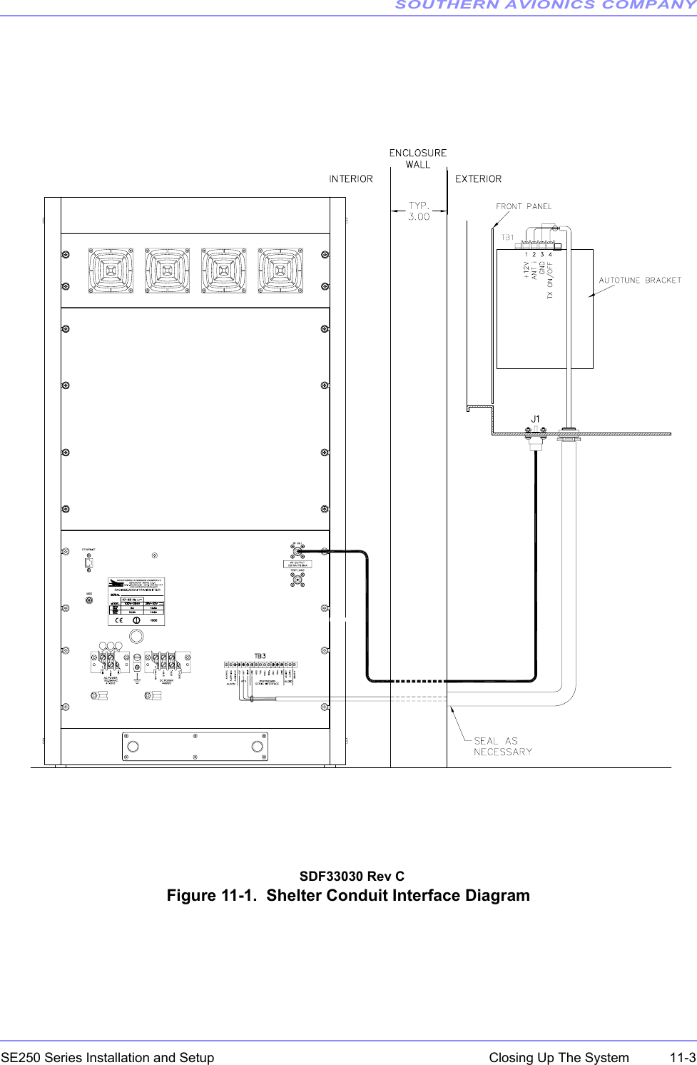
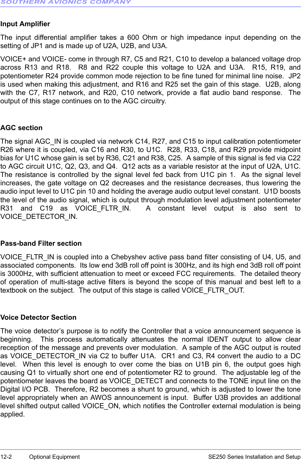
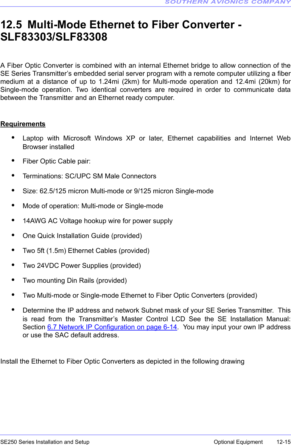
![SOUTHERN AVIONICS COMPANYSE250 Series Installation and Setup 6-1System Site Configuration6 System Site Configuration6.1 Control Program InitializationOnce the SE250 has been installed, the system is ready for operation. The unit is powered on bythe AC main breaker switch located on the Power Control Panel. Actuating this breaker beginsthe initialization process. The SE250 will proceed through two initialization screens on the LCDindicating which version of firmware is being used. When communicating with the factory, pleasehave the version available. The system will default to transmitter 1 as the primary transmitter;LCD data on TX1, Monitor Enabled, FWD POWER meter, PA VOLTS meter, and System Statusare also primary. All other functions are turned OFF. The initialization screens are as follows:SE250 Southern Avionics Company Beaumont Texas USA Firmware Version X.XX © 2011 SE250 Initialization System Please wait … MM-DD-YYYY SE250 8-bit;1-stop;ODD-parity;19200 NO XON/XOFF RCU ID: 0 SE SERIES [DUAL] Fault: NONE RF Frequency Setting ........ 320000 Hz Tone Frequency Setting ........ 400 Hz Call Sign: SAC TX Mode:IDENT](https://usermanual.wiki/Southern-Avionics/SE250/User-Guide-2164388-Page-67.png)
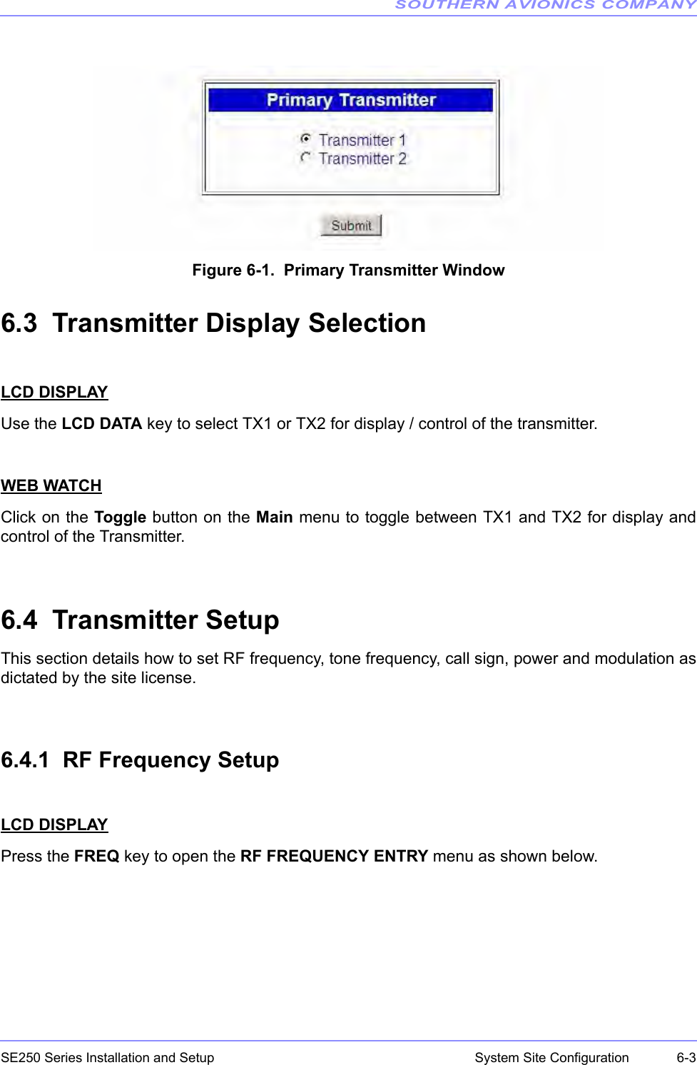
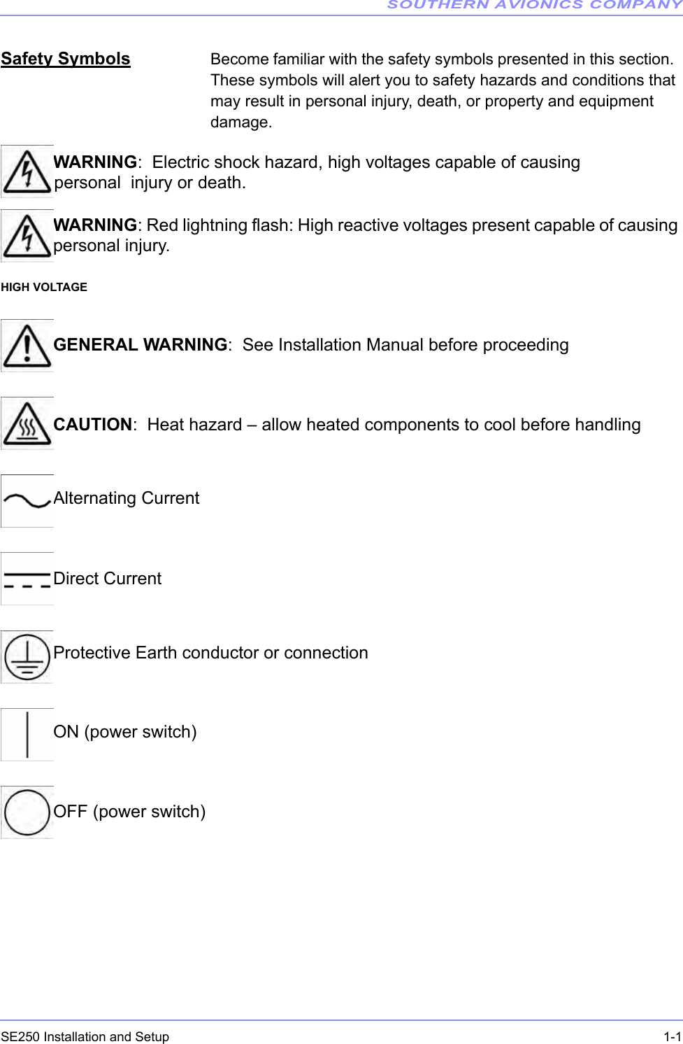
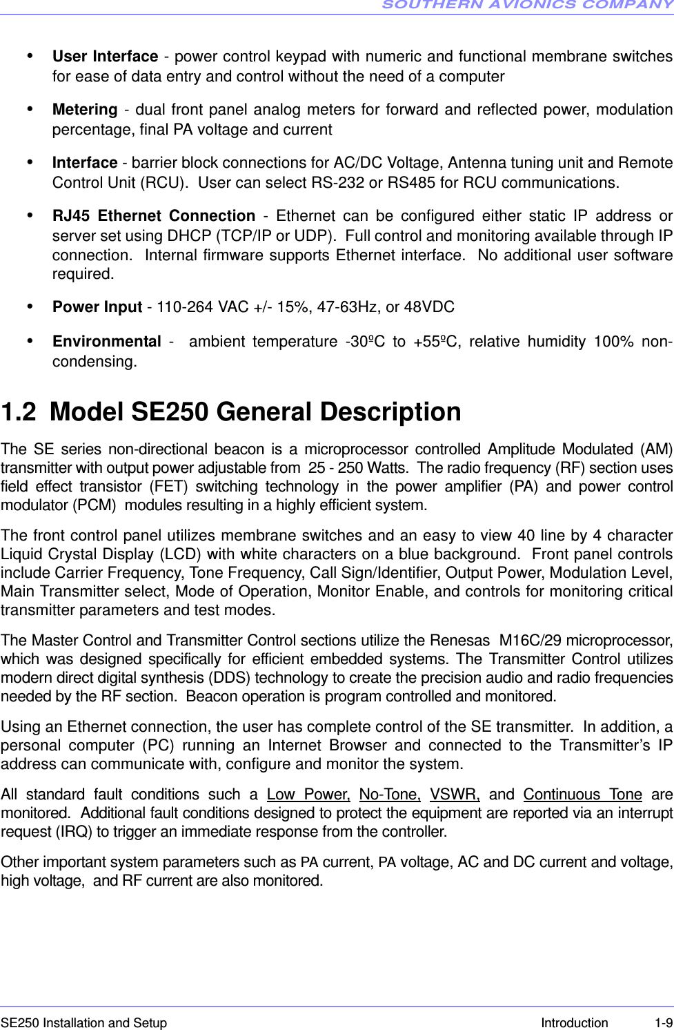
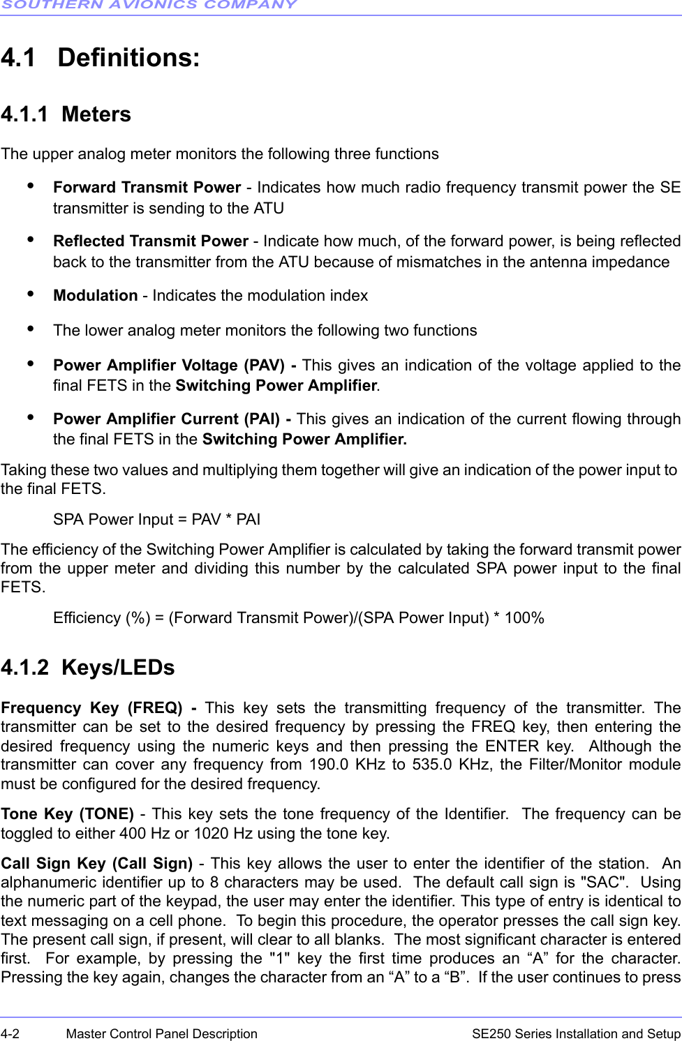
![SOUTHERN AVIONICS COMPANYSE250 Series Installation and Setup6-4 System Site ConfigurationRepeat pressing the FREQ key to clear then enter the desired frequency in the field. When the ENTER key is pressed, the RF power level will be set to 0 Watts immediately to protectthe transmitter.Press SPCL FCTN then 1 to store any changes.WEB WATCHIn the SE SERIES TRANSMITTER Web Watch window, click on Setup in the right column boxon the Main window to open the Transmitter 1/2 : Setup window shown in Figure 6-2. WebGUI Transmitter Setup Window on Page 6-4.Figure 6-2. Web GUI Transmitter Setup WindowAfter making changes, click the Set button to send the value to Transmitter Control boardmemory.Click the Back button to close the Transmitter Setup window and return to the Main window.RF FREQUENCY ENTRY FREQ should be between 190K and 535K Hz Enter RF Frequency: [ 320000] Hz](https://usermanual.wiki/Southern-Avionics/SE250/User-Guide-2164388-Page-70.png)
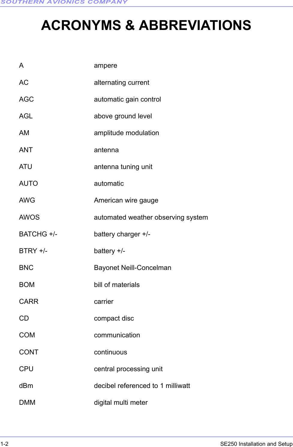
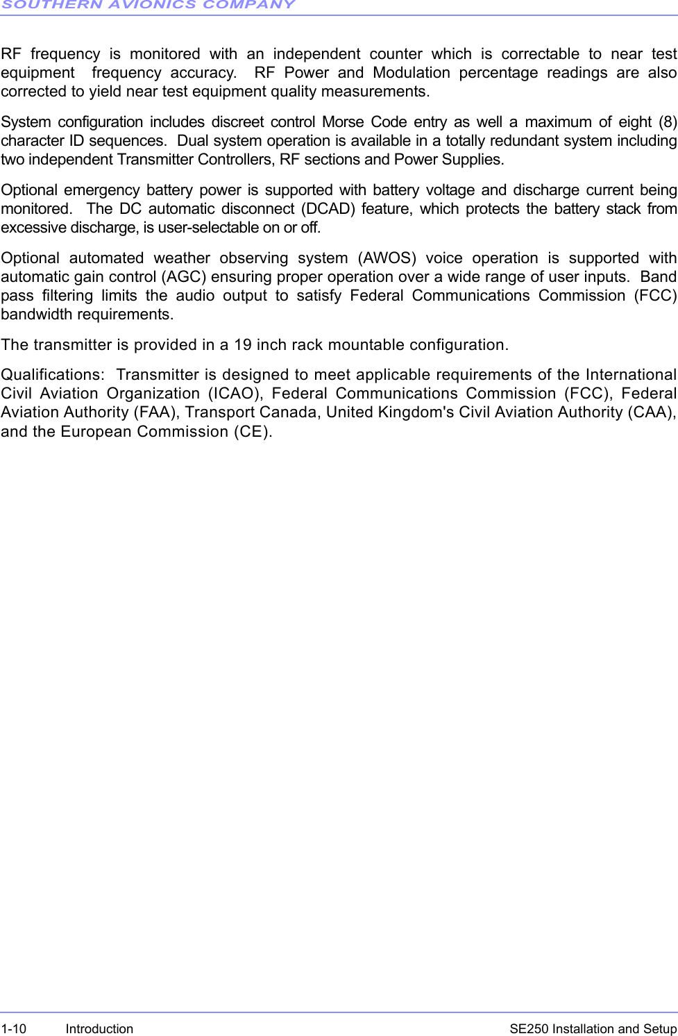
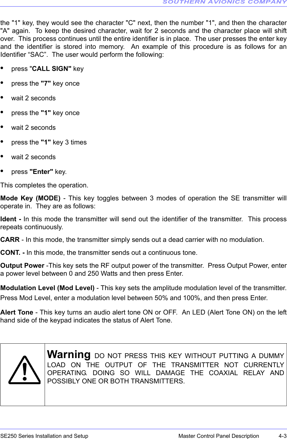
![SOUTHERN AVIONICS COMPANYSE250 Series Installation and Setup6-8 System Site Configuration6.4.4 Transmitter Mode SetupThere are three options CARR, CONT, IDENT.LCD DISPLAYPress the MODE key to toggle the CARR, CONT, IDENT Example: change from IDENT to CARR by pressing the MODE key on the LCD screen as shownbelowWEB WATCHSelect the desired mode from the pulldown menu and click on Set to send the mode to theTransmitter Control board memory.6.4.5 RF Power Level SetupLCD DISPLAYPress the OUTPUT POWER key to open the RF POWER SETTING menu, as shown belowCaution Ensure that the RF Frequency setting corresponds to that of theFilter PCB. SE SERIES [DUAL] Fault: NONE RF Frequency Setting ......... 320000 Hz Tone Frequency Setting ....... 400 Hz Call Sign: SAC TX Mode: CARR](https://usermanual.wiki/Southern-Avionics/SE250/User-Guide-2164388-Page-74.png)
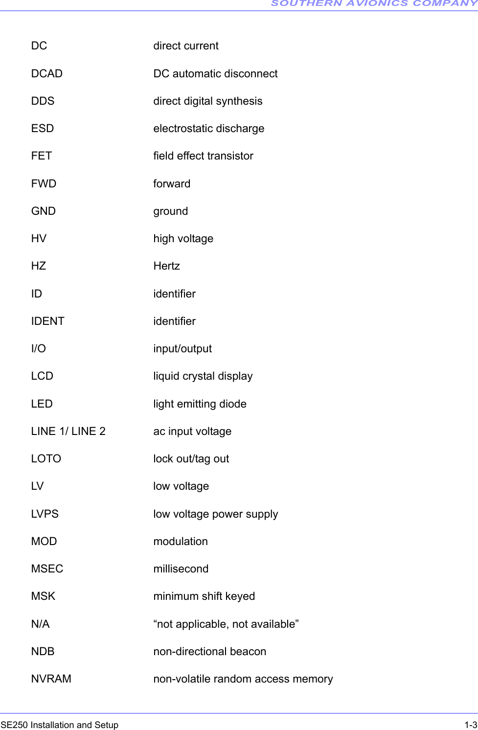
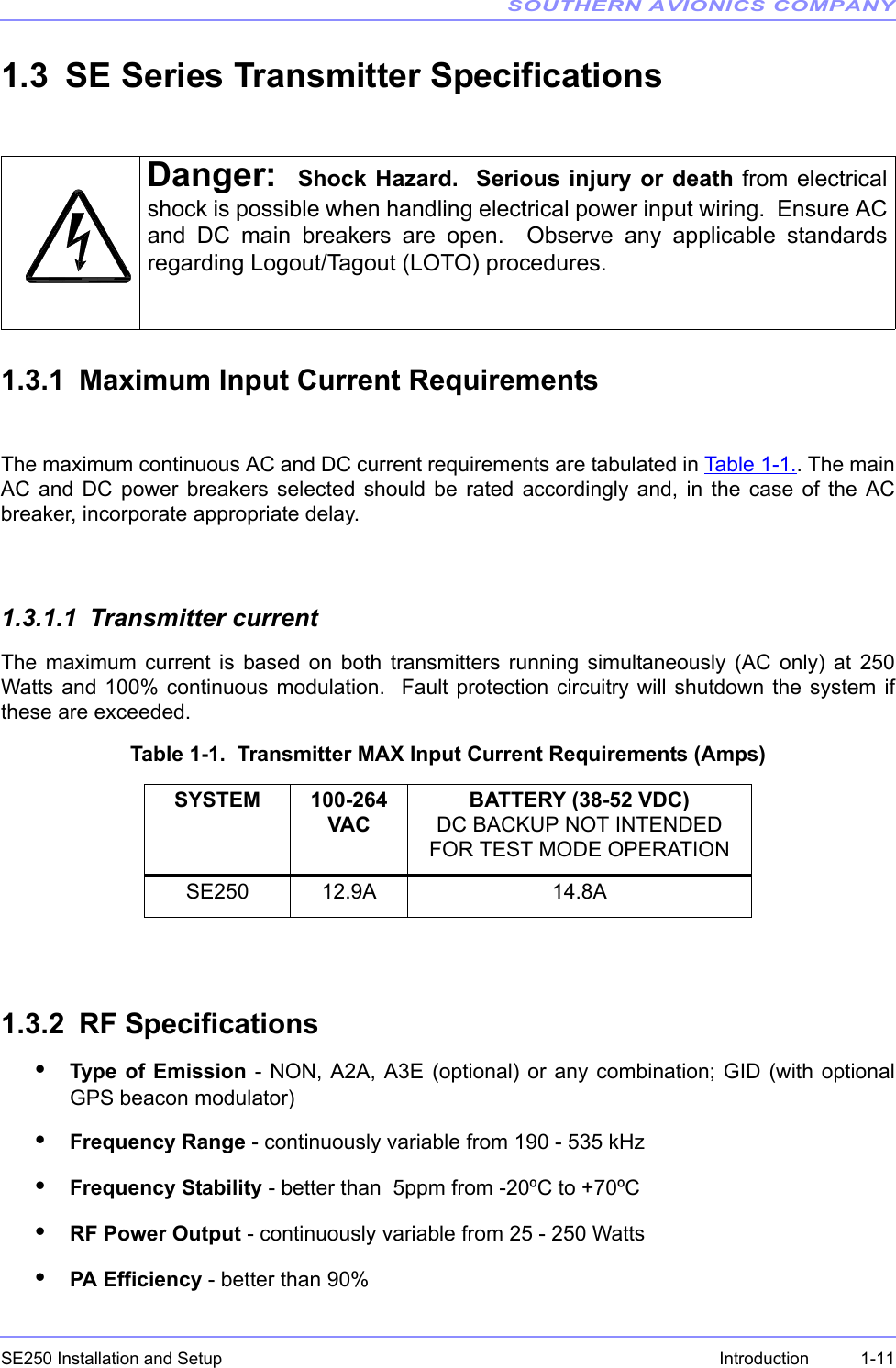
![SOUTHERN AVIONICS COMPANYSE250 Series Installation and Setup 6-9System Site ConfigurationRepeat pressing the OUTPUT POWER key to clear the RF power level in the field box. Enter thedesired power using the keypad.When the ENTER key is pressed, the Master Control will send the desired level to TransmitterControl board memory.WEB WATCHOperates similarly to the LCD DISPLAY above.6.4.6 Modulation Level SetupLCD DISPLAYPress the MOD LEVEL key to open the MODULATION SETTING menu, as shown belowRepeat pressing the MOD LEVEL key to clear the modulation level in the field box.Enter the mod level desired using the keypad.WEB WATCHOperates similar to the LCD DISPLAY above. ---------- RF POWER SETTING ---------- POWER should be between 0 and 250. Enter RF Power Level: [250] watts ---------- MODULATION SETTING --------- MOD Level should be between 0% and 100%. Enter Modulation Level: [ 95]%](https://usermanual.wiki/Southern-Avionics/SE250/User-Guide-2164388-Page-75.png)
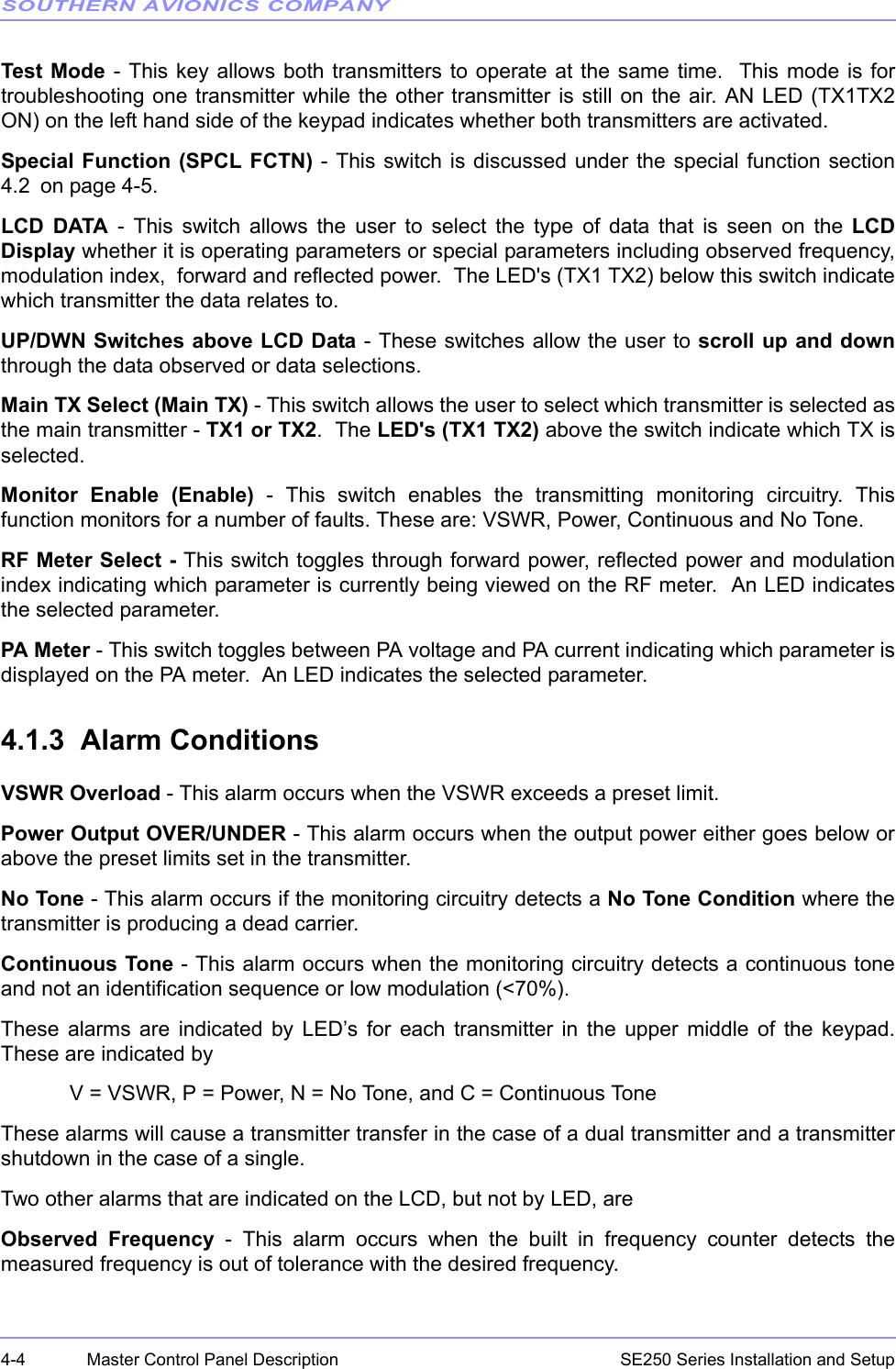
![SOUTHERN AVIONICS COMPANYSE250 Series Installation and Setup6-10 System Site Configuration6.5 Transmitter CalibrationThis section details how to calibrate the RF Frequency output, the RF output power, theModulator output and the RF power displayed.Using the SPCL FCTN key to open the special function menu as shown belowSelect the 8 key to open the calibration menu as shown below6.5.1 (Power factor) Calibration (output adjustment)Transmitters are factory calibrated at 250W for an operating range of 25-250 Watts. Powercalibration should only be done locally with the system connected to a 50 Ohm dummy load, orincorrect readings could result.LCD DISPLAYPress the 1 key to open the POWER FACTOR CALIBRATION menu, as shown below. 1=STORE 7=PWR TEST 2=LOGGING 8=CALIBRATE 5=RCU 9=SYSTEM 6=ID TEST Select the following key --------------- 1.Power Factor Cal 4.Power Display Error 2.MOD Factor Cal 3.Frequency Calibration ------ POWER FACTOR CALIBRATION ------- Power Factor should be between 5 and 250. Enter power factor: [100]](https://usermanual.wiki/Southern-Avionics/SE250/User-Guide-2164388-Page-76.png)
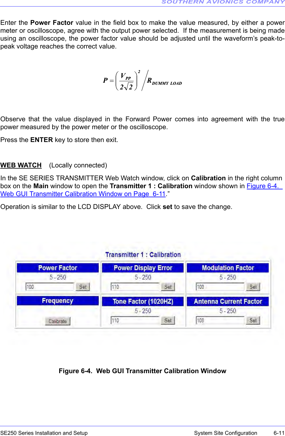
![SOUTHERN AVIONICS COMPANYSE250 Series Installation and Setup6-12 System Site Configuration6.5.2 Modulation Factor Calibration (display adjustment)LCD DISPLAYPress the 2 key to open the MODULATION CALIBRATION menu, as shown below.Set the modulation level to 100%. Verify that this is actually 100% modulation by monitoring theRF waveform envelope on the dummy load. Vary the MOD Factor and press enter. Do this untilthe displayed modulation is 95%WEB WATCH (Locally connected)Operates similar to the LCD DISPLAY above. See Figure 6-4. Web GUI Transmitter CalibrationWindow on Page 6-11.6.5.3 Frequency Calibration (display adjustment)LCD DISPLAYPress the 3 key to open the FREQUENCY CALIBRATION menu, as shown below.Enter the measurement from the test frequency counter and press the ENTER key. After a fewmoments, the measured frequency displayed on the LCD screen should agree with the testequipment measurement. After a few seconds, the screen returns to the home menuautomatically. ---- MODULATION FACTOR CALIBRATION ---- MOD Factor should be between 5 and 250. Enter modulation factor: [100] -------- FREQUENCY CALIBRATION ------- Setting: 320000HZ Measured:320000HZ ENTER = Calibrate](https://usermanual.wiki/Southern-Avionics/SE250/User-Guide-2164388-Page-78.png)
![SOUTHERN AVIONICS COMPANYSE250 Series Installation and Setup 6-13System Site ConfigurationWEB WATCH (Locally connected)Operates similar as LCD DISPLAY above. See Figure 6-4. Web GUI Transmitter CalibrationWindow on Page 6-116.5.4 Power Display Error Calibration (display adjustment)Note: Scope connected to 50 Ohm dummy load to read true ouput power.LCD DISPLAYPress the 4 key to open the POWER TARGET CALIBRATION menu, as shown below.Change the factor number and press return to achieve the proper LCD RF power readoutagreeing with the scope.WEB WATCHNONE6.5.5 Antenna CalibrationLCD DISPLAYNONEWEB WATCH See Figure 6-4. Web GUI Transmitter Calibration Window on Page 6-11•Under Calibration, verify the antenna factor is set to 10 (default).•The displayed value of antenna current should be made to agree with the value on theATU meter by adjusting the factor until identical readings are achieved. --- POWER DISPLAY ERROR CALIBRATION --- P.D.E Factor should be between 5 and 250 Enter power target factor: [100]](https://usermanual.wiki/Southern-Avionics/SE250/User-Guide-2164388-Page-79.png)
![SOUTHERN AVIONICS COMPANYSE250 Series Installation and Setup6-14 System Site ConfigurationWhen the transmitter calibration is complete, click the Back button to close the TransmitterCalibration window and return to the Main window.6.6 DCAD (DC Automatic Disconnect)LCD DISPLAYPress the SPCL FCTN key, then the 9 key to open the SE SYSTEM menu, as shown below.Press the 1 key repeat to toggle “ON” or “OFF” on the LCD screen, then the ENTER key to exit.ENTER must be pressed to store the selection. WEB WATCHOperates similar to the LCD DISPLAY above.6.7 Network IP ConfigurationLCD DISPLAYPress the SPCL FCTN key, then the 9 key to open the SE SYSTEM menu, as shown below. -------------- SE SYSTEM ------------- 1. DCAD . . . . . . . . . . . . . . [OFF] 2. Network Press ENTER key to confirm, then exit. -------------- SE SYSTEM ------------- 1. DCAD . . . . . . . . . . . . . . [OFF] 2. Network Press ENTER key to confirm, then exit.](https://usermanual.wiki/Southern-Avionics/SE250/User-Guide-2164388-Page-80.png)
![SOUTHERN AVIONICS COMPANYSE250 Series Installation and Setup 6-15System Site ConfigurationPress the 2 key to open the Network IP on the LCD screen, then select one of the followingnumbers:1 DHCP2 IP Address3Netmask4 GatewayPress the Enter key to confirm the Network IP settings.WEB WATCH (Read Only)In the SE SERIES TRANSMITTER Web Watch window, click on the IP Configuration from theright column box on the Main menu to open the Network : IP Configuration window, shown inFigure 6-5. Web GUI Network IP Configuration Window on Page 6-15.Figure 6-5. Web GUI Network IP Configuration Window 1. DHCP: [ENABLED] 2. IP Address: 192.168.1.122 3. Netmask: 255.255.255.0 Press ENTER 4. Gateway: 192.168.1.1 to confirm](https://usermanual.wiki/Southern-Avionics/SE250/User-Guide-2164388-Page-81.png)
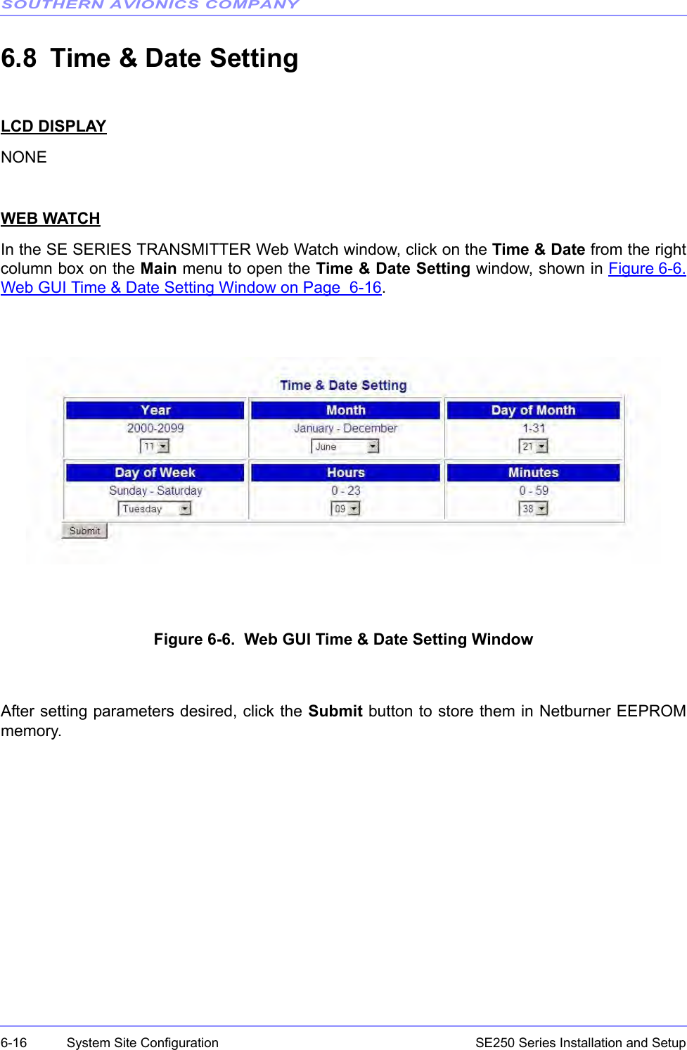
![SOUTHERN AVIONICS COMPANYSE250 Series Installation and Setup 6-17System Site Configuration6.9 Location Site SettingLCD DISPLAYNONEWEB WATCHIn the SE SERIES TRANSMITTER Web Watch window, click on the Location Site in the rightcolumn box on the Main window to open the Location Site window, shown in Figure 6-7. WebGUI Location Site Window on Page 6-17.Figure 6-7. Web GUI Location Site WindowA maximum of 30 characters are allowed for the location site name. Click the Submit button tostore in (EEPROM) memory on the NETBURN board.6.10 Monitor EnableLCD DISPLAYPress the ENABLE key to open the MONITOR menu, as shown below (transmitter 1 is selected).Press ENABLE to toggle “ENABLED” or “DISABLED” on the LCD screen, then the ENTER keyto exit. ENTER must be pressed to store the selection. ------------ TRANSMITTER 1 ----------- MONITOR . . . . . . . . . . . . [ENABLED] Press ENTER key to confirm, then exit.](https://usermanual.wiki/Southern-Avionics/SE250/User-Guide-2164388-Page-83.png)
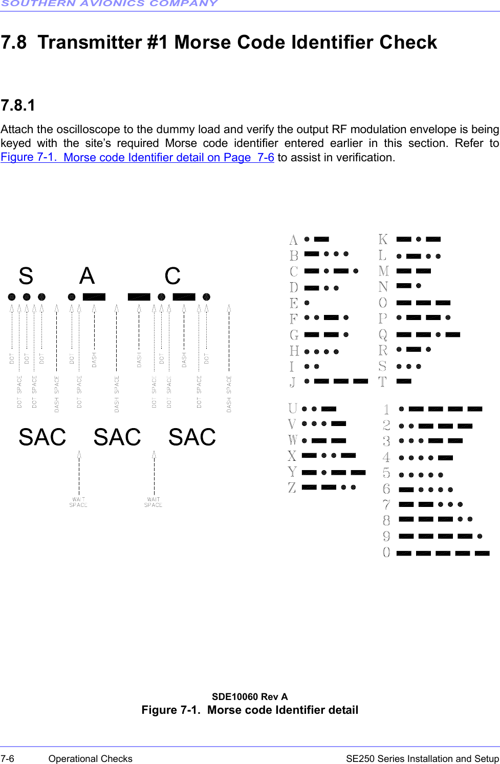
![SOUTHERN AVIONICS COMPANYSE250 Series Installation and Setup7-2 Operational Checks7.5 Transmitter #1 RF Power Level Checks7.5.1Connect an oscilloscope or a calibrated power meter to the system's RF output at the dummy load.7.5.2Use the MAIN TX key to select TX1 as primary transmitter. Green LED’s will illuminate indicatingwhich TX is Primary. Select TX1 as Primary.7.5.3Use the LCD DATA key to select TX1 as the display / control transmitter data.7.5.4In the Monitor section press the ENABLE key until “Disabled” is displayed on the LCD. PressENTER to store this condition. This action will be necessary until shutdown testing is performedlater in this section.7.5.5Press the FREQ key to open the RF FREQUENCY ENTRY menu, as shown below. SE250 Initialization System Please wait … MM-DD-YYYY SE SERIES [DUAL] Fault: NONE RF Frequency Setting ......... 320000 Hz Tone Frequency Setting ....... 1020 Hz Call Sign: SAC TX Mode:IDENT](https://usermanual.wiki/Southern-Avionics/SE250/User-Guide-2164388-Page-98.png)
![SOUTHERN AVIONICS COMPANYSE250 Series Installation and Setup 7-3Operational Checks7.5.6Enter the desired frequency of operation using the numeric keypads then press ENTER to storethe selection. (If necessary press the FREQ key repeatedly to clear the RF frequency field). 7.5.7Press the TONE key to toggle between 400 Hz and 1020 Hz modulation frequency.7.5.8Enter the desired call-sign using the numeric keypads then press ENTER to store the selection.Press the CALL SIGN key to open the CALL SIGN ENTRY menu, as shown below. (If necessarypress the CALL SIGN key repeatedly to clear the call sign field). 7.5.9Press the MODE key to toggle the CARR, IDENT, CONT., to Carrier Mode (CARR).7.5.10Press the OUTPUT POWER key to open the RF POWER SETTING menu, as shown below.RF FREQUENCY ENTRY FREQ should be between 190K and 535K Hz Enter RF Frequency: [ 320000] Hz CAL SIGN ENTRY Enter 1 to 8 Characters Entry Call Sign: SAC](https://usermanual.wiki/Southern-Avionics/SE250/User-Guide-2164388-Page-99.png)
![SOUTHERN AVIONICS COMPANYSE250 Series Installation and Setup7-4 Operational Checks7.5.11Key in the desired power level for the site and press ENTER to store and activate that level. In afew seconds, the power output level selected should register on the meter and voltage on the PAmeter should be indicated. Record the readings for PA voltage and PA current for reference data to be used in Section10 for proper Antenna tuning and matching. 7.5.12Verify the output RF power level measured at the dummy load agrees (within 5%) with the valuedisplayed on the LCD in the Transmitter 1 section.7.6 Transmitter #1 Modulation Level Check7.6.1Press the MOD LEVEL key to open the MODULATION SETTING menu, as shown below.Press the MOD LEVEL key repeatedly to clear the modulation level box.Enter 95% modulation and press ENTER to store that level. ---------- RF POWER SETTING ---------- POWER should be between 0 and 250. Enter RF Power Level: [250] watts ---------- MODULATION SETTING --------- MOD Level should be between 0% and 100%. Enter Modulation Level: [ 95]%](https://usermanual.wiki/Southern-Avionics/SE250/User-Guide-2164388-Page-100.png)
![SOUTHERN AVIONICS COMPANYSE250 Series Installation and Setup 7-7Operational Checks7.8.2This completes general operational tests of transmitter #1.7.9 Transmitter #2 RF Power Level Checks 7.9.1Connect an oscilloscope or a calibrated power meter to the system's RF output at the dummy load.7.9.2Use the MAIN TX key to select TX2 as primary transmitter. Green LED’s will illuminate indicatingwhich TX is Primary. Select TX2 as Primary.7.9.3Use the LCD DATA key to select TX2 as the display / control transmitter data.7.9.4In the Monitor section press the ENABLE key until “Disabled” is displayed on the LCD. PressENTER to store this condition. This will be necessary until shutdown testing is performed later inthis section.7.9.5Press the FREQ key to open the RF FREQUENCY ENTRY menu, as shown below.7.9.6Enter the desired frequency of operation using the numeric keypads then press ENTER to storethe selection. (If necessary press the FREQ key repeatedly to clear the RF frequency field). RF FREQUENCY ENTRY FREQ should be between 190K and 535K Hz Enter RF Frequency: [ 320000] Hz](https://usermanual.wiki/Southern-Avionics/SE250/User-Guide-2164388-Page-103.png)
![SOUTHERN AVIONICS COMPANYSE250 Series Installation and Setup7-8 Operational Checks7.9.7Press the TONE key to toggle between 400 HZ and 1020 HZ modulation frequency.7.9.8Enter the desired call-sign using the numeric keypads then press ENTER to store the selection.Press the CALL SIGN key to open the CALL SIGN ENTRY menu, as shown below. 7.9.9Press the MODE key to toggle the CARR, IDENT, CONT. to Carrier Mode (CARR).7.9.10Press the OUTPUT POWER key to open the RF POWER SETTING menu, as shown below.7.9.11Key in the desired power level for the site and press ENTER to store and activate that level. In afew seconds, the power output level selected should register on the meter and voltage on the PAmeter should be indicated.7.9.12Verify the output RF power level measured at the dummy load agrees (within 5%) with the valuedisplayed on the LCD in the Transmitter 2 section. CAL SIGN ENTRY Enter 1 to 8 Characters Entry Call Sign: SAC ---------- RF POWER SETTING ---------- POWER should be between 0 and 250. Enter RF Power Level: [250] watts](https://usermanual.wiki/Southern-Avionics/SE250/User-Guide-2164388-Page-104.png)
![SOUTHERN AVIONICS COMPANYSE250 Series Installation and Setup 7-9Operational Checks7.10 Transmitter #2 Modulation Level Check7.10.1Press the MOD LEVEL key to open the MODULATION SETTING menu, as shown below.Press the MOD LEVEL key repeatedly to clear the modulation level box.Enter 95% modulation and press ENTER to store that level.7.10.2Scope the modulation waveform and record the max/min envelope values to calculate themodulation percentage. (vmax-vmin)/(vmax+vmin)=mod%7.10.3Verify the set modulation percentage (displayed on the LCD) and the calculated modulationpercentage agree to within 5%.7.11 Transmitter #2 Frequency Checks7.11.1As an example, when calibrating RF output frequency, International Civil Aviation Organization(ICAO) regulations state a maximum variance of + 100 parts per million (ppm) Hertz is allowedprovided the ouput frequency is less than 1606.5 kHz. ---------- MODULATION SETTING --------- MOD Level should be between 0% and 100%. Enter Modulation Level: [ 95]%](https://usermanual.wiki/Southern-Avionics/SE250/User-Guide-2164388-Page-105.png)