Spotwave Wireless SPOTCELL0001 Indoor unit (SCU unit) User Manual SpotCell100
Spotwave Wireless Ltd. Indoor unit (SCU unit) SpotCell100
UserManual.wiki
>
Spotwave Wireless
>
SPOTCELL0001 User Manual
>
Users manual
Contents
1.
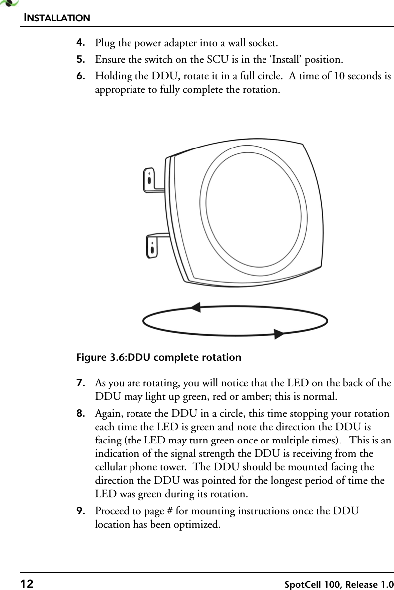
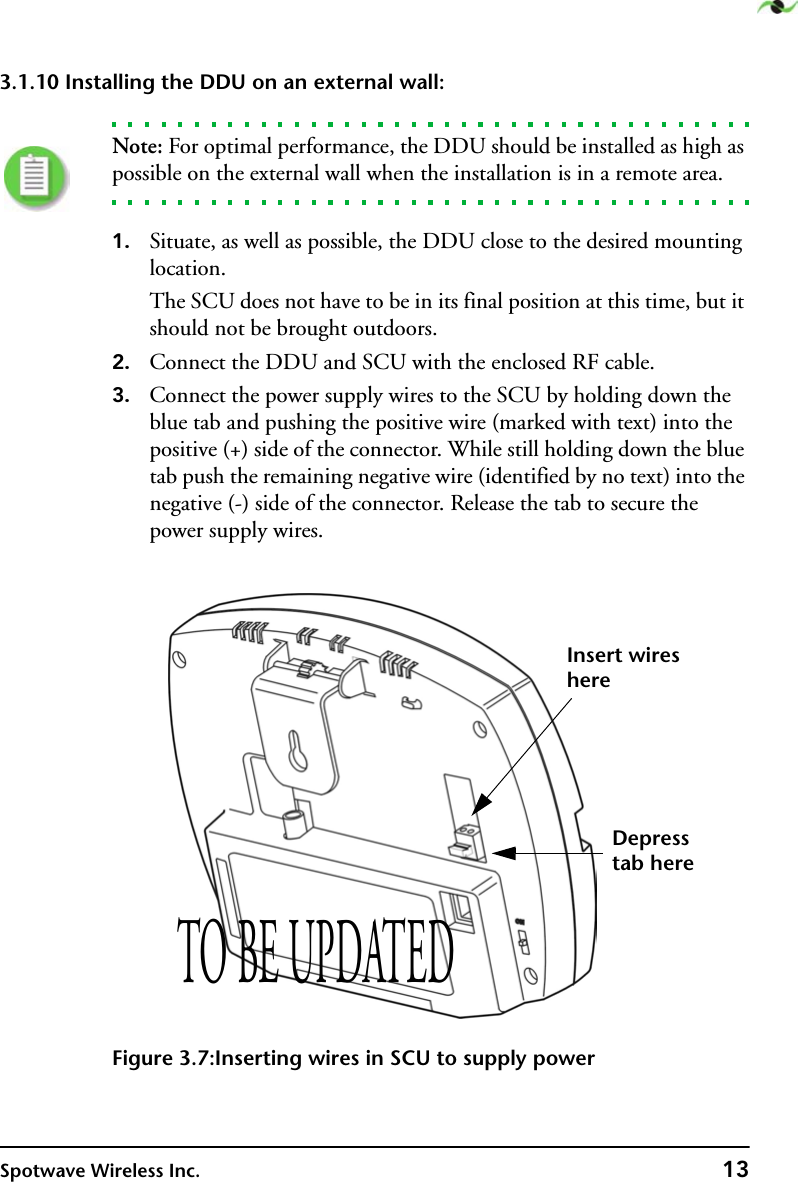
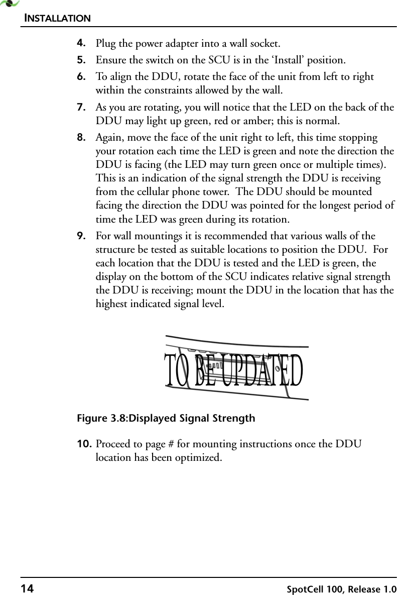
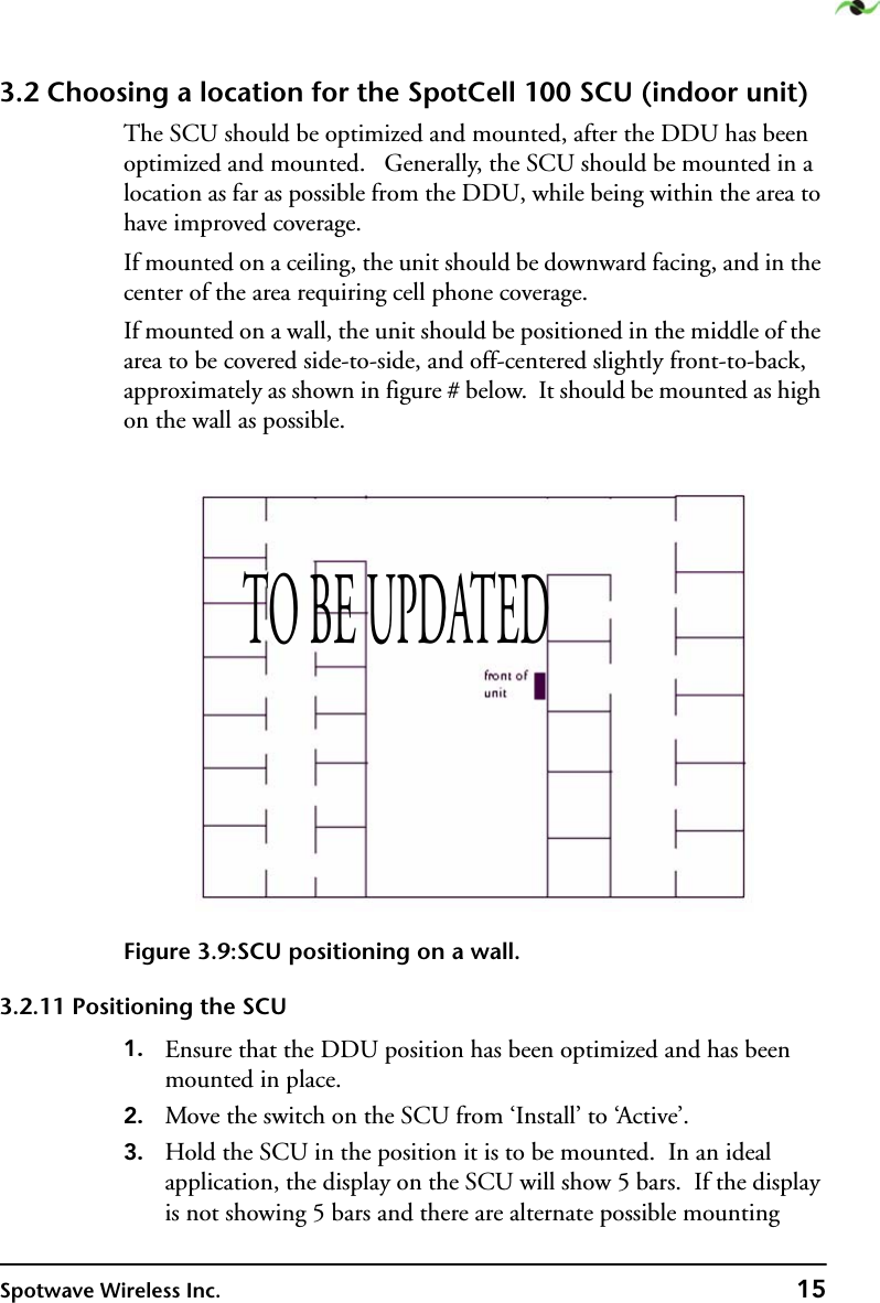
Installation manual
2.
Users manual
3.
Revised manual with safety notice
Users manual
Navigation menu
Upload a User Manual
Namespaces
Wiki Guide
HTML
PDF
Info
Views
User Manual
Discussion / Help
Navigation