St Jude Medical SJMRFB RF implantable medical device User Manual
St. Jude Medical RF implantable medical device
UserManual.wiki
>
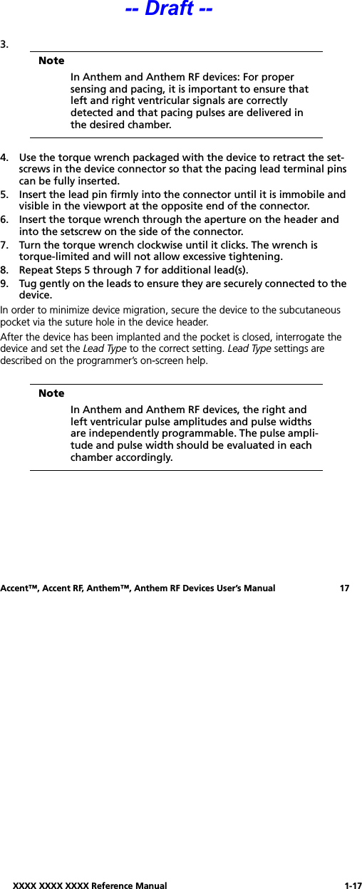
St Jude Medical
>
SJMRFB User Manual
Users Manual
Navigation menu
Upload a User Manual
Namespaces
Wiki Guide
HTML
PDF
Info
Views
User Manual
Discussion / Help
Navigation

![1-4 Warnings and Precautions4 Warnings and PrecautionsBackup VVI Operation. In rare instances, the device may revert to Backup VVI operation at the programmed settings listed in Table 2. These values are not programmable. When the device has reverted to Backup VVI operation, the programmer dis-plays a pop-up message indicating that the device is operating at the Backup VVI values. Press [Continue] and follow the on-screen instructions.Elective Replacement Indicator (ERI). At ERI, the nominal life of the device is three months. When the device exhibits signs of ERI, described on page 18, it should be replaced expeditiously.Patient follow-up visits should be scheduled at an appropriate frequency so that ERI can be detected well before End-of-Life (EOL).Noninvasive Programmed Stimulation (NIPS). Life-threatening ventricular tachycardia or fibrillation may occur during NIPS, therefore: (1) closely monitor the patient, and (2) make defibrillation and resuscitation equipment, and trained personnel, readily available during testing. Only physicians trained in tachycardia induction and reversion protocols should use NIPS. For more infor-mation on NIPS, refer to the programmer’s on-screen help.Ventricular Support Pacing during NIPS testing (Accent Model PM2110, Accent RF Model PM2210, Anthem, and Anthem RF devices only) is delivered Parameter ValueAccent™ Anthem™Mode VVI VVIBase Rate 67.5 ppm 67.5 ppmVentricular Pacing Chamber NA LV —> RVPulse Configuration Unipolar RV Unipolar TipLV Unipolar TipSense Configuration Unipolar Tip RV Unipolar TipPulse Amplitude 5.0 V 5.0 VPulse Width 0.6 ms 0.6 msRefractory Period 337 ms 337 msSensitivity 2.0 mV 2.0 mVInterventricular Delay NA 16 msTable 2. Backup VVI Settings-- Draft --](https://usermanual.wiki/St-Jude-Medical/SJMRFB/User-Guide-1093070-Page-6.png)