Star Solutions 1-05-00-02-1 CELLULAR BASESTATION User Manual mm2000 bssIIC
Star Solutions International Inc CELLULAR BASESTATION mm2000 bssIIC
UserManual.wiki
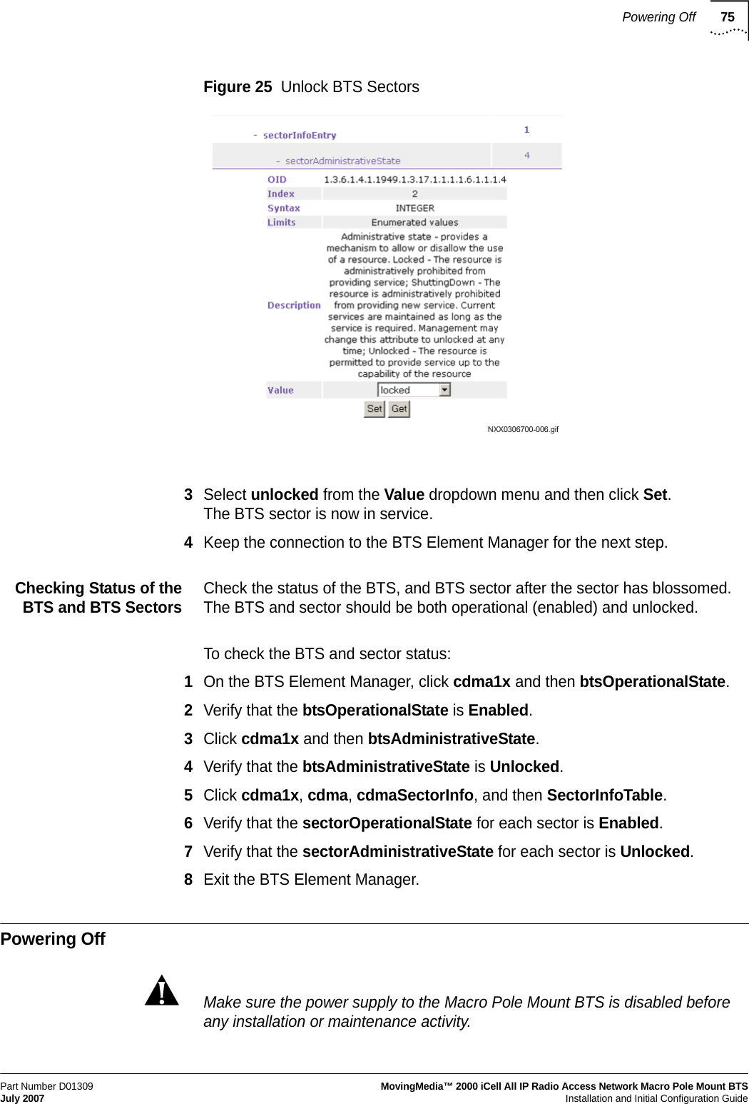
>
Star Solutions
>
1 05 00 02 1 User Manual
USERS MANUAL
Navigation menu
Upload a User Manual
Namespaces
Wiki Guide
HTML
PDF
Info
Views
User Manual
Discussion / Help
Navigation


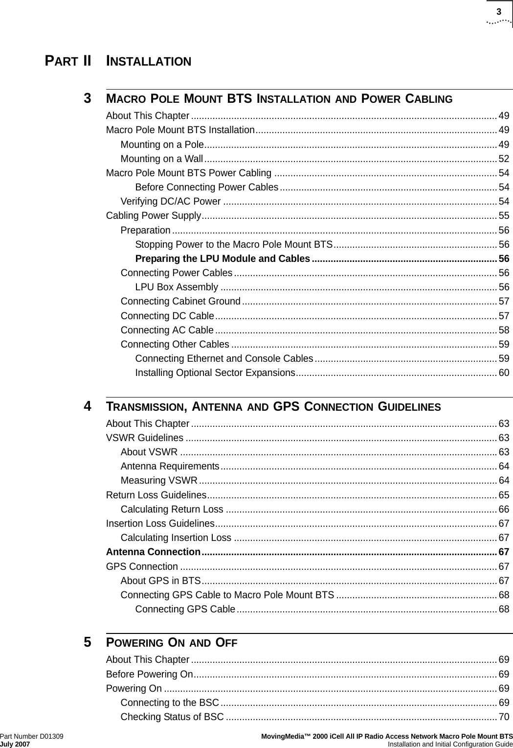
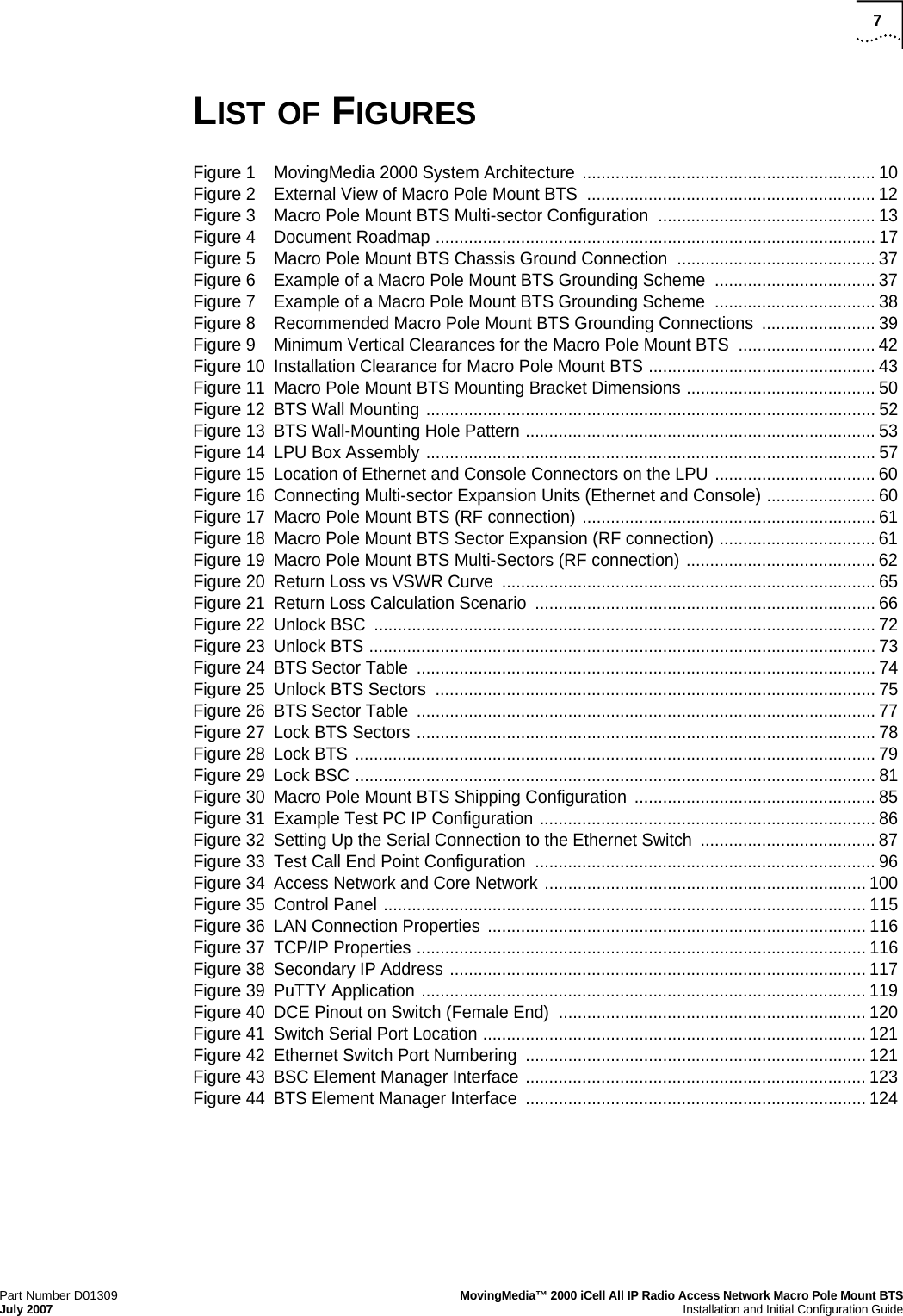
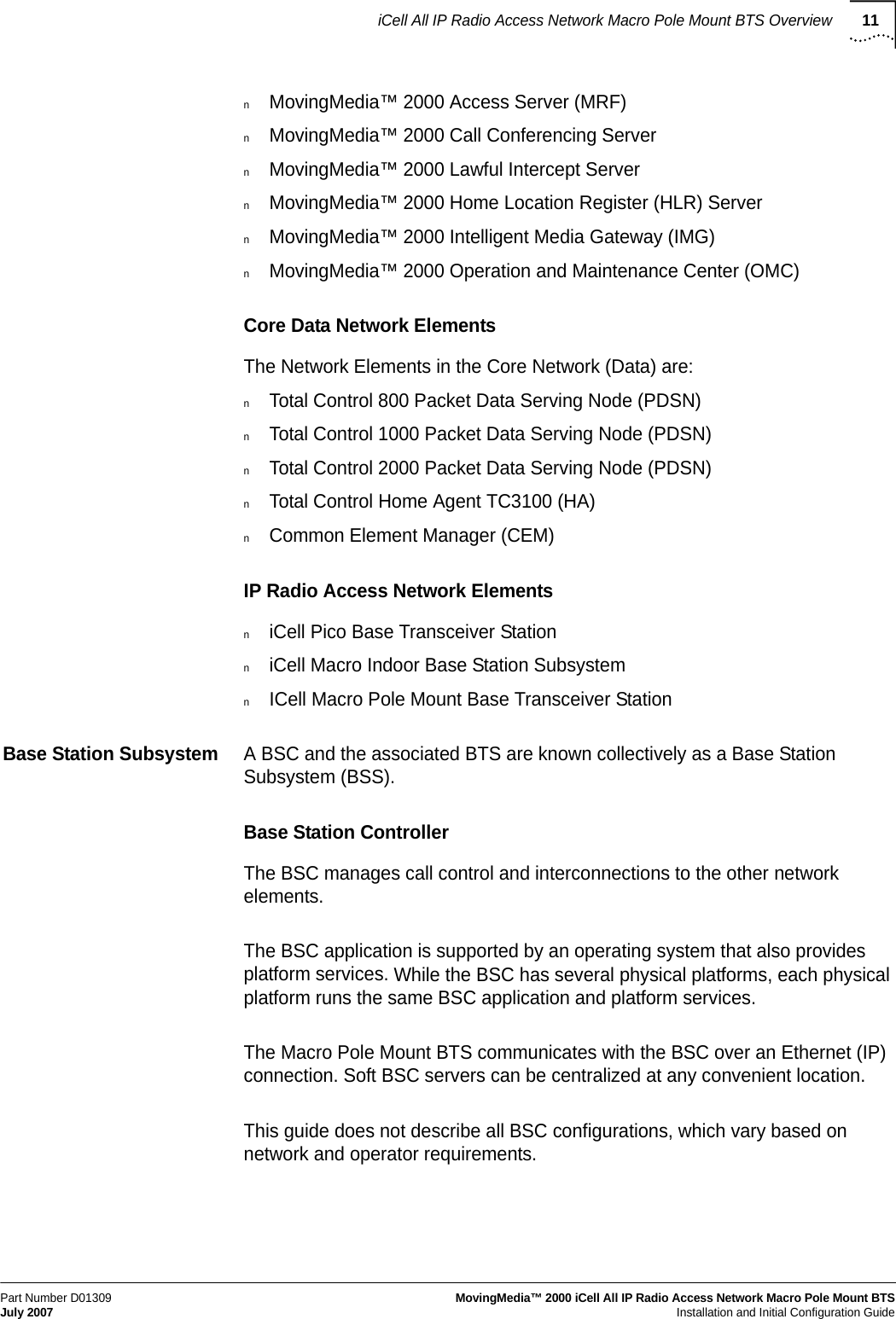
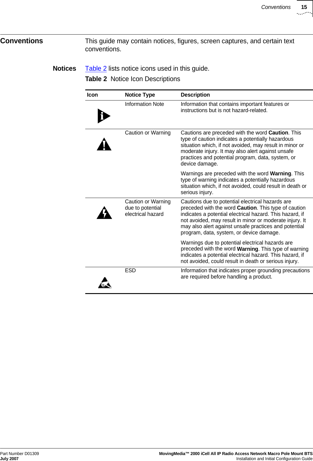

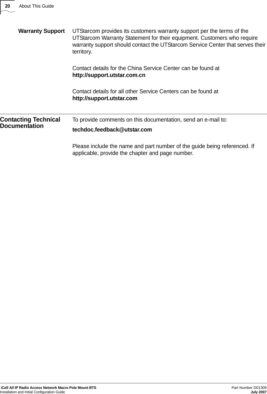
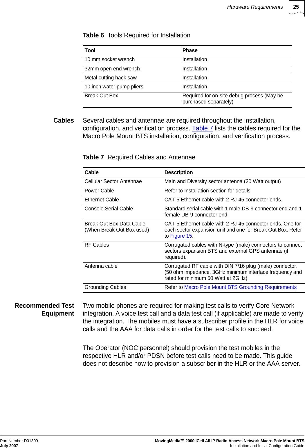
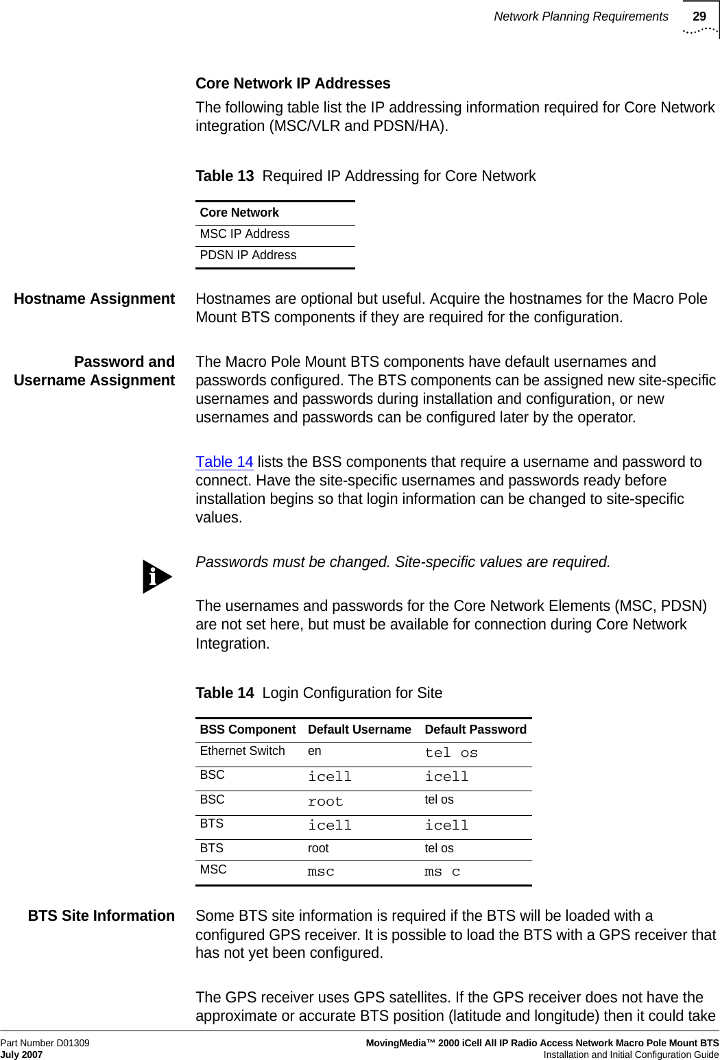

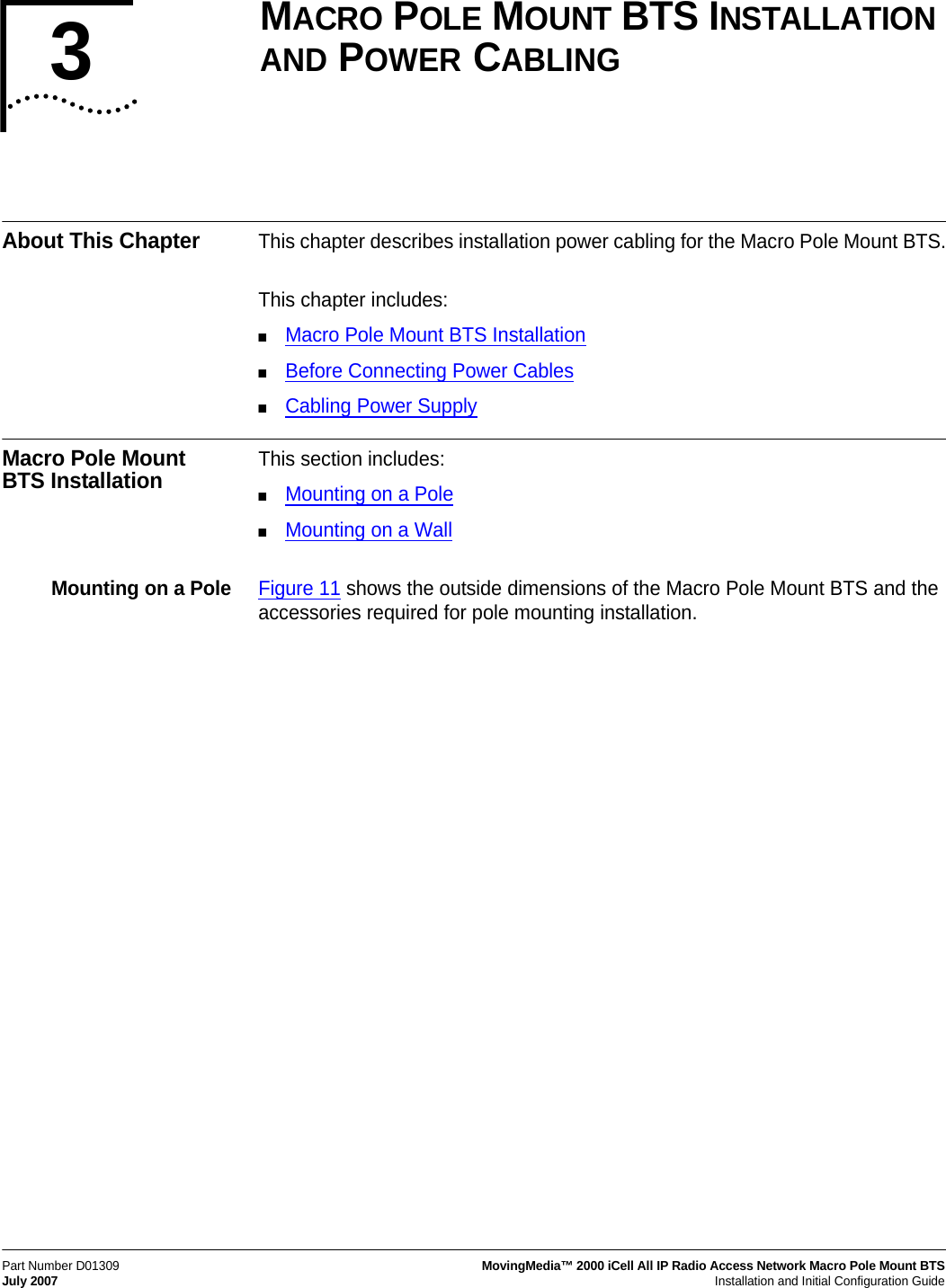
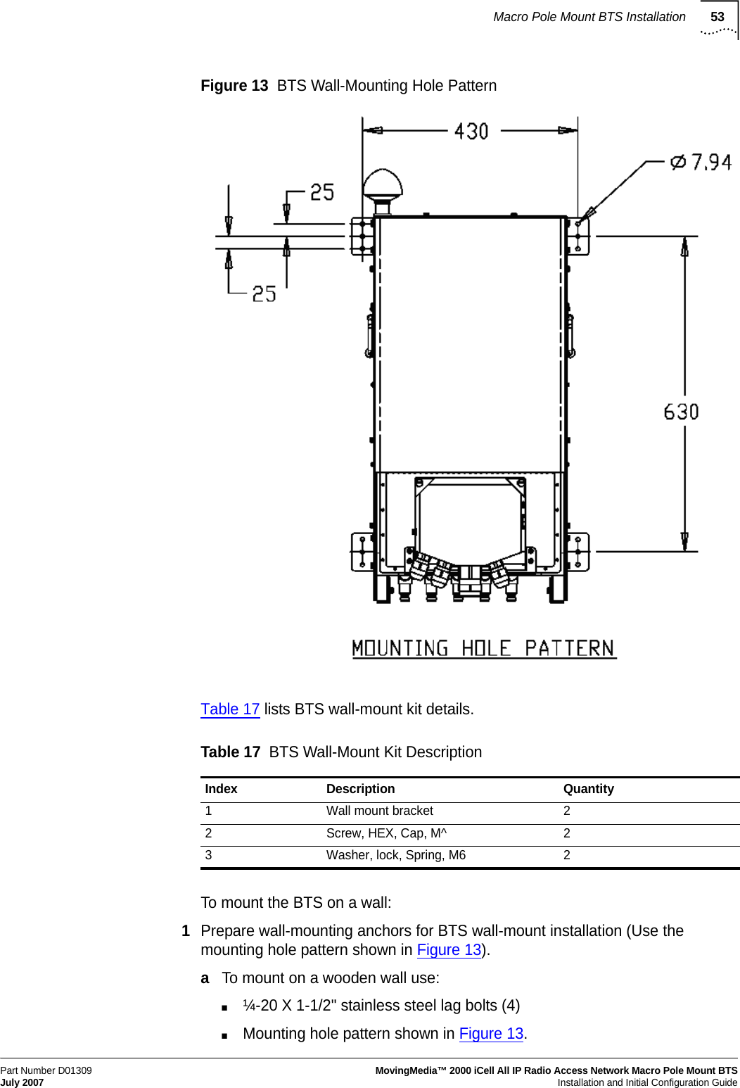
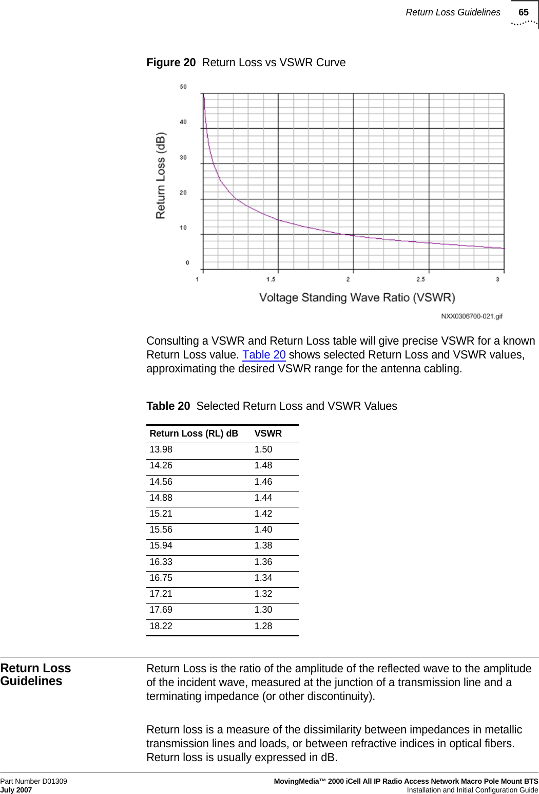
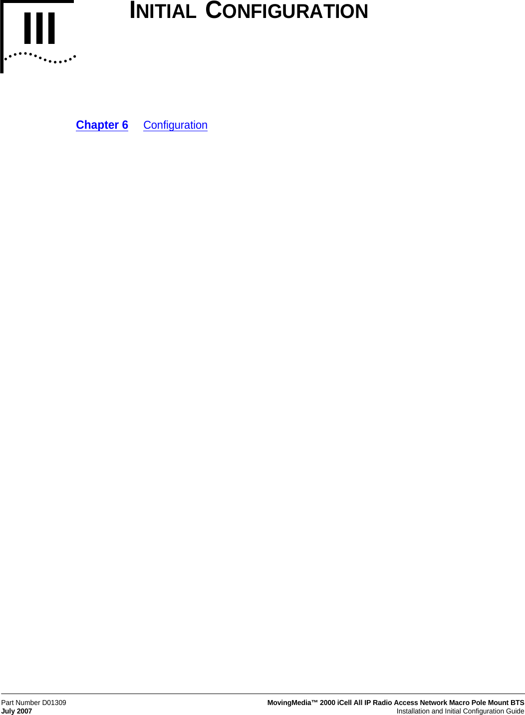
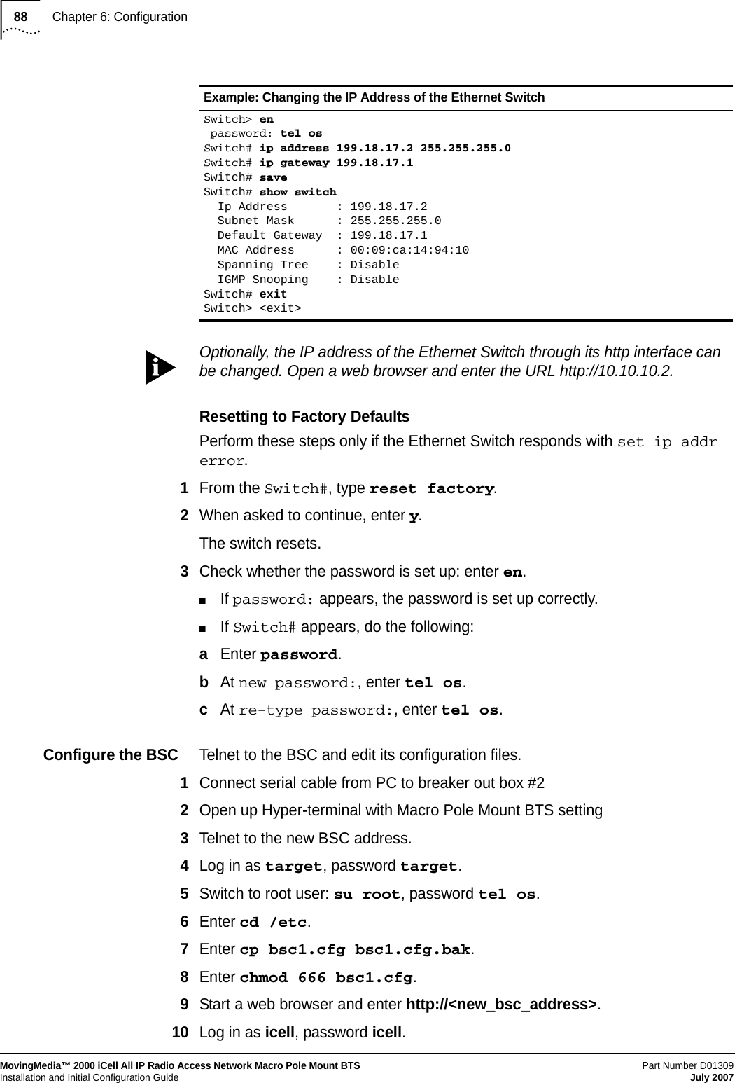
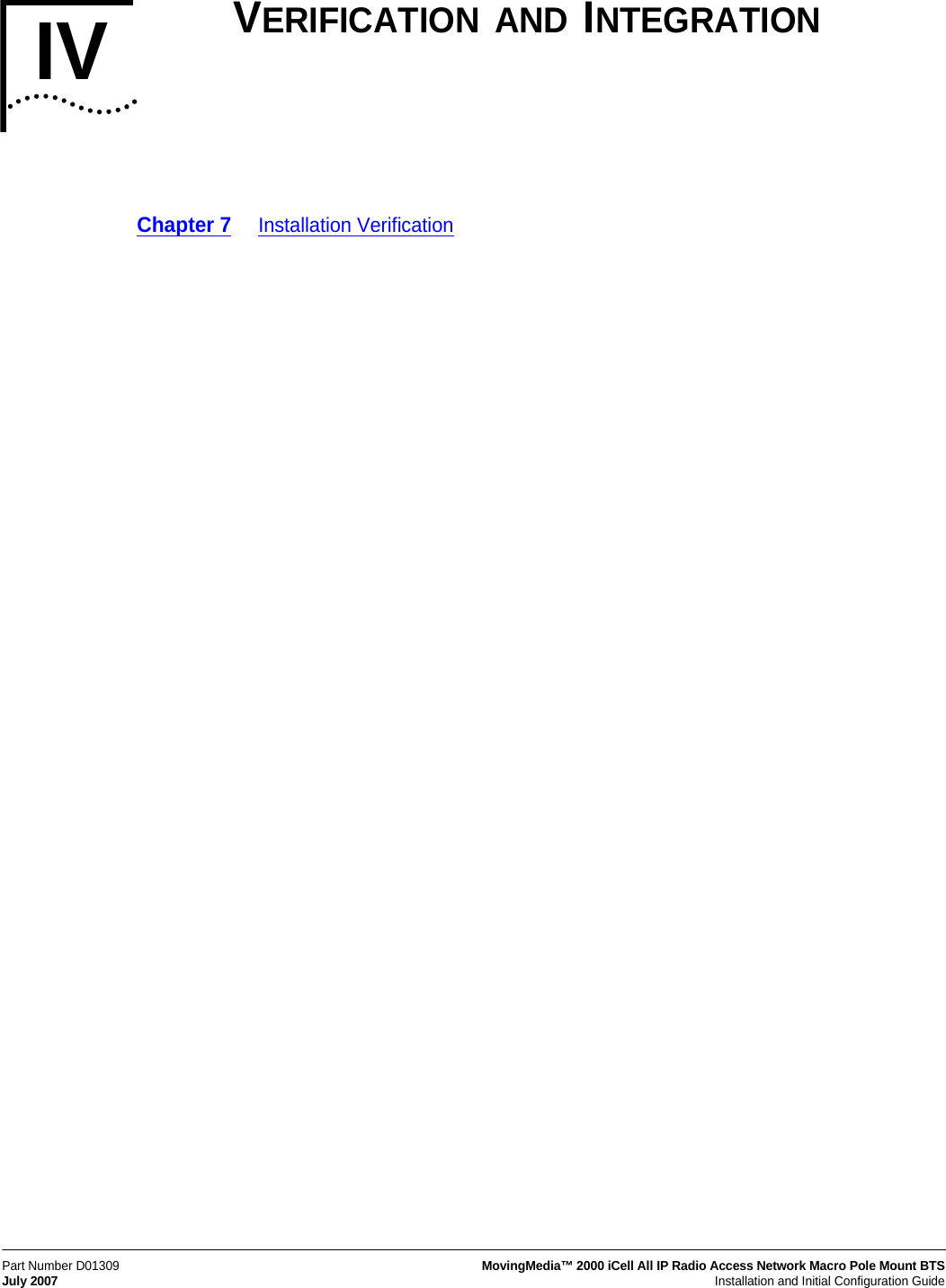
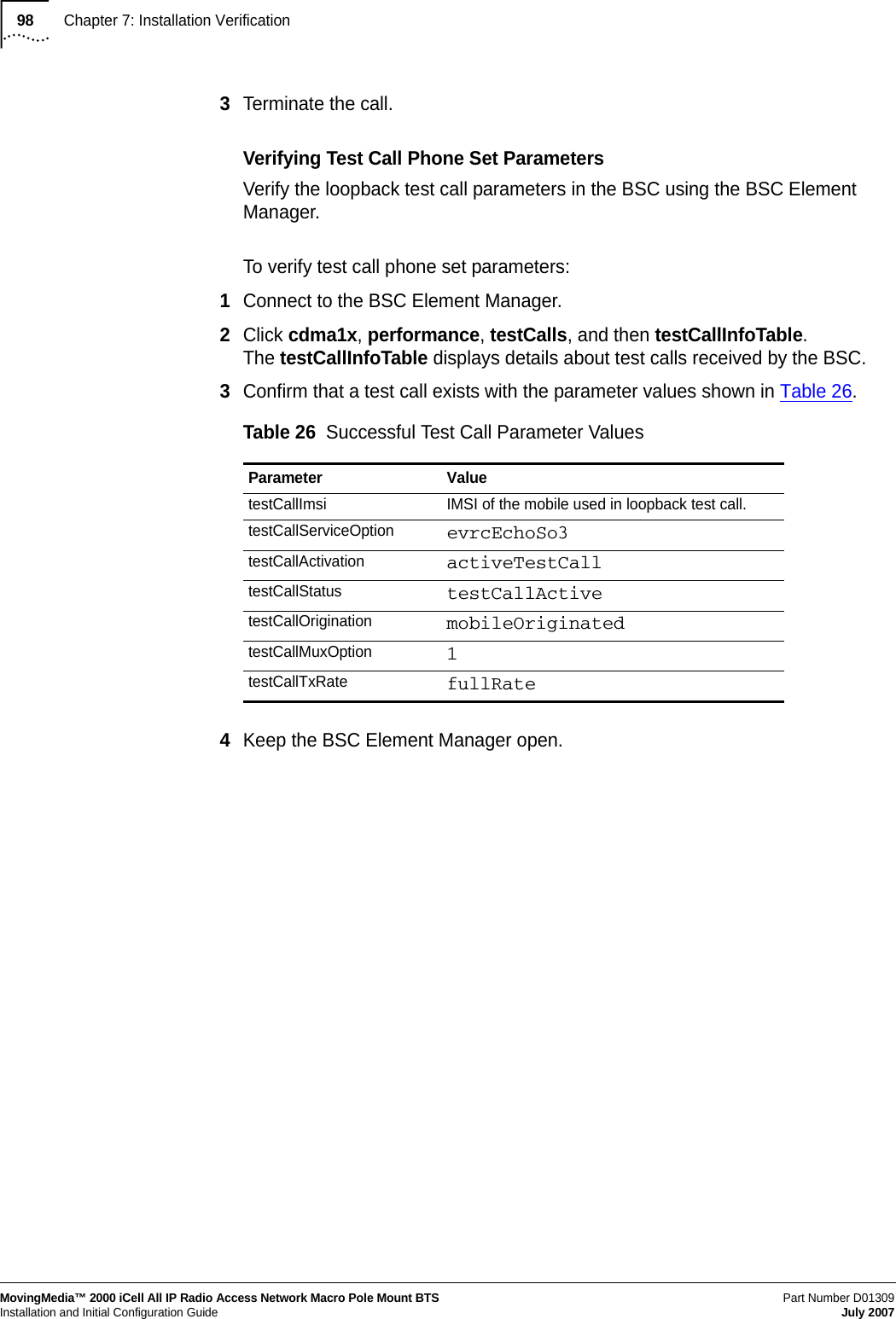
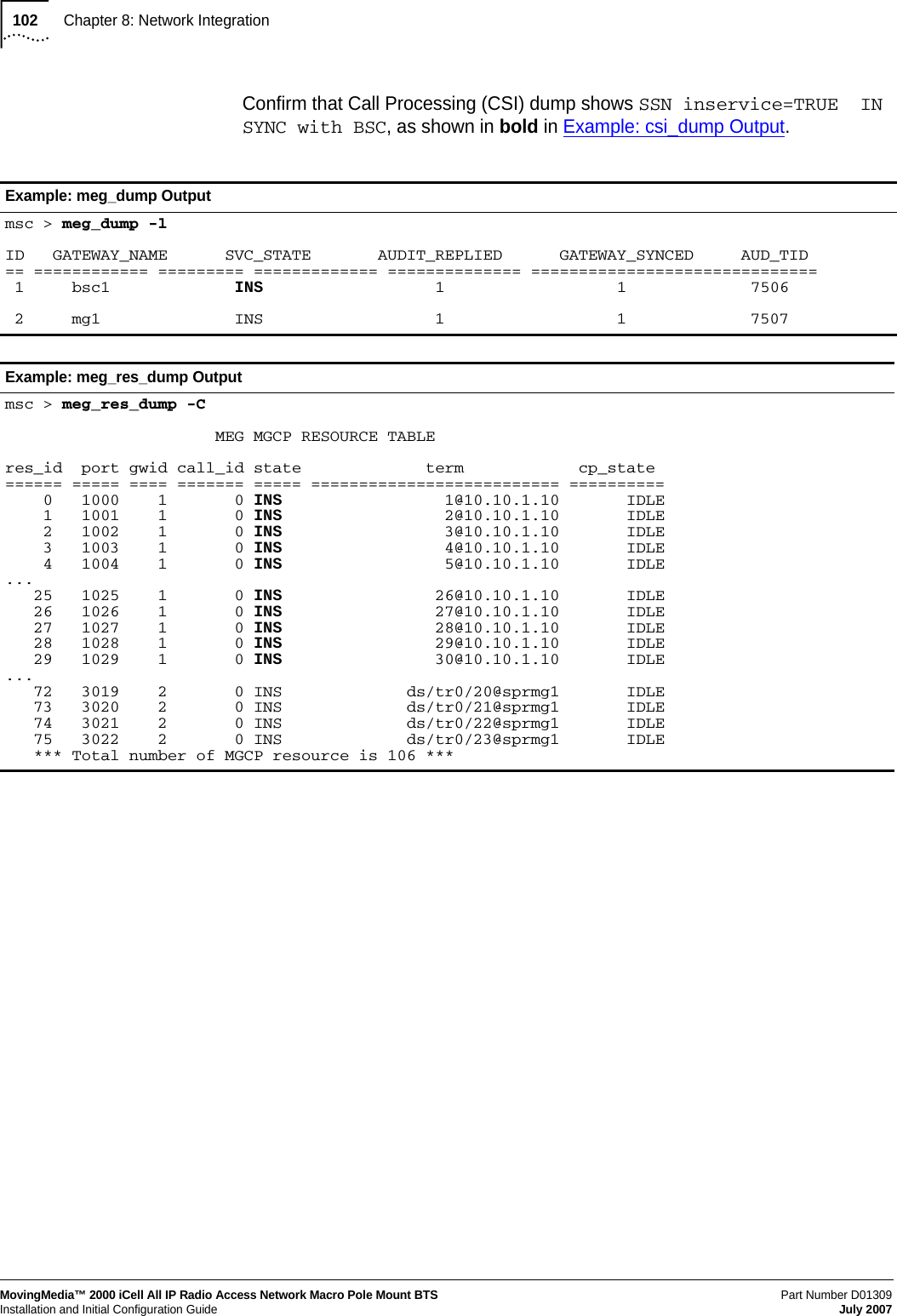
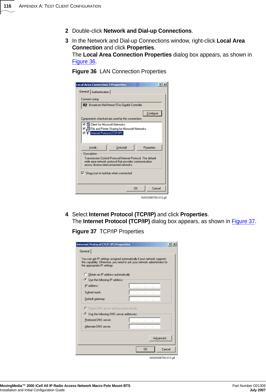
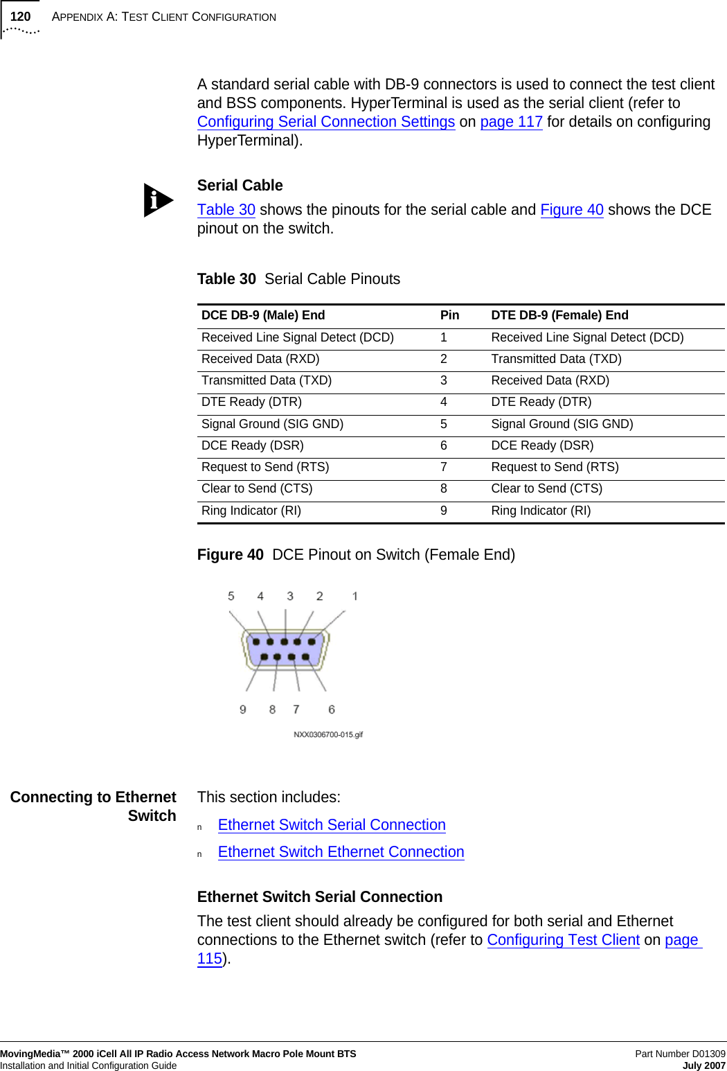
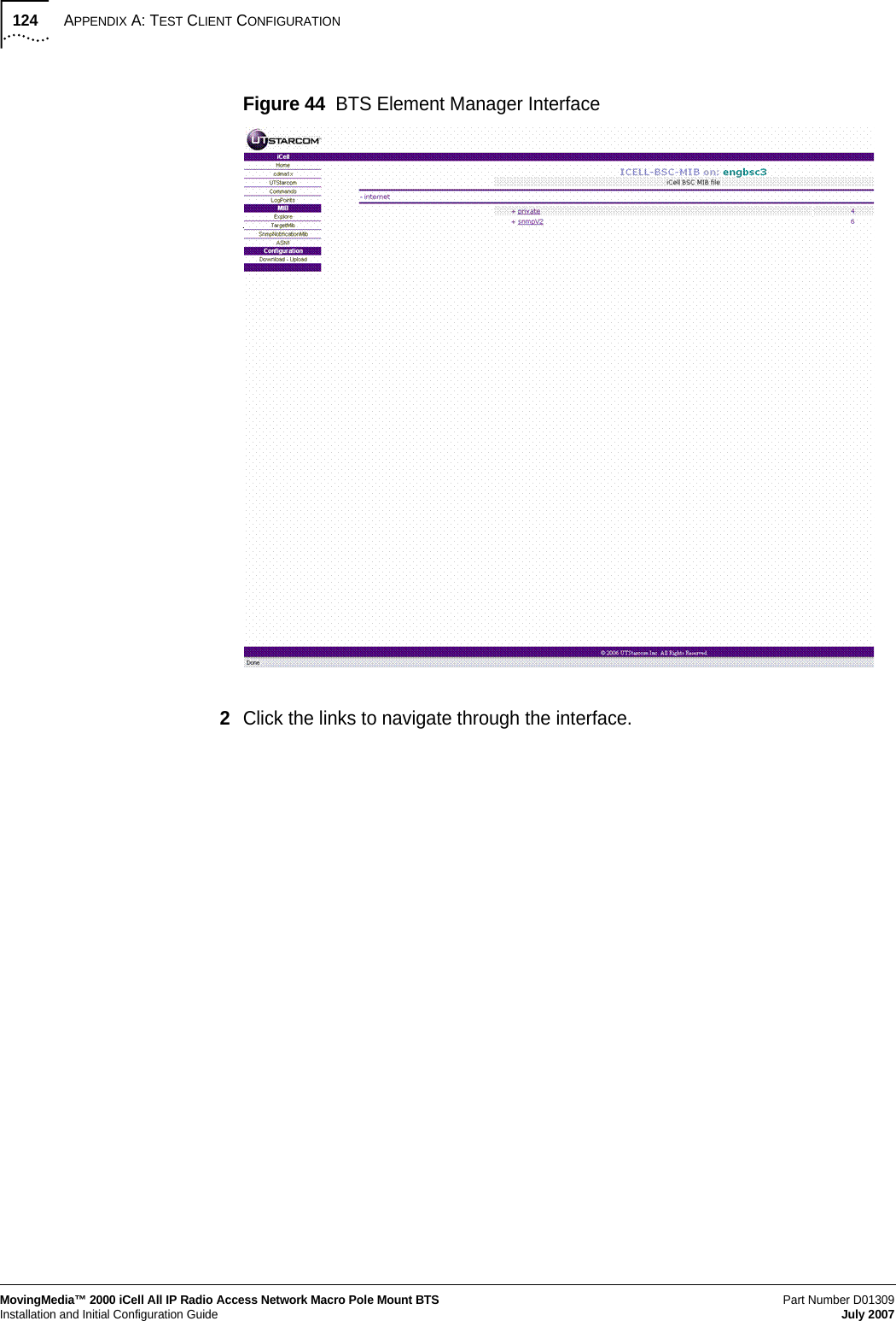
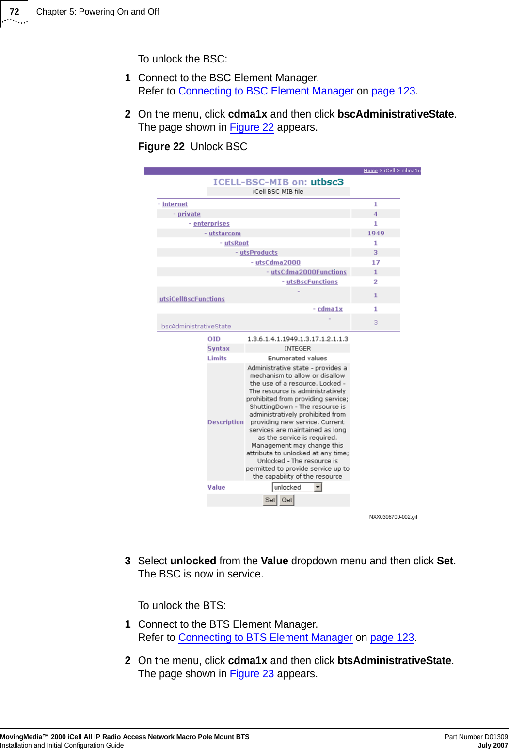
![70Chapter 5: Powering On and OffMovingMedia™ 2000 iCell All IP Radio Access Network Macro Pole Mount BTSPart Number D01309 Installation and Initial Configuration Guide July 2007To connect to the BSC using an Ethernet connection:1Connect to the BSC using Telnet or SSH:aTo Telnet to the BSC:> telnet <BSC IP Address>Login as icellbTo SSH to the BSC using the target username:> ssh target@<BSC IP address> target@<BSC IP address>'s password: [target@<hostname> target]$Change to the root user:> su - root [root@<BSC Name> root]#Checking Status of BSC Check the status of the BSC. The BSC should be both operational (enabled) and unlocked.To check BSC status:1Connect to the BSC Element Manager, using HTTP GUI interface.2Select cdma1x to the right of GUI interface, then select bscOperationalState.3Confirm that the bscOperationalState is enabled.4Select cdma1x, then bscAdministrativeState.5Verify that the bscAdministrativeState is Unlocked.Checking BSC Application Status To check the BSC application status:1Enter icell_bsc status to view application status:[icell@bsc7 icell]$icell_bsc statusTable 21 Default BSC Login ParametersParameter ValueDefault IP address10.10.10.10icell Passwordicellroot Passwordtel osuser target target](https://usermanual.wiki/Star-Solutions/1-05-00-02-1/User-Guide-847688-Page-72.png)
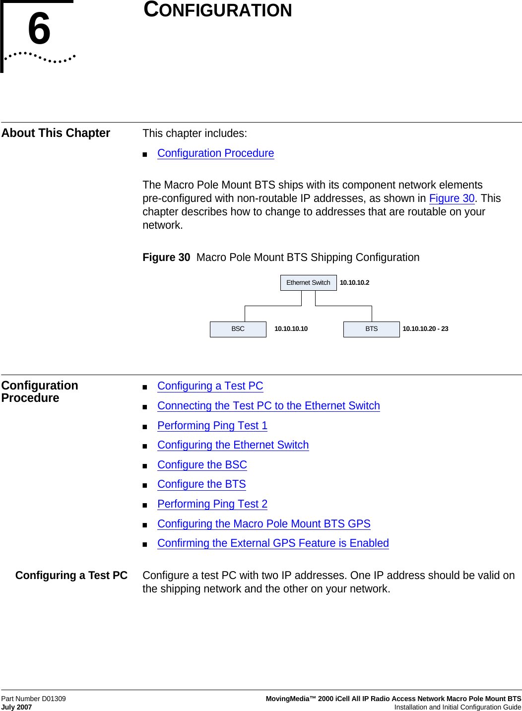
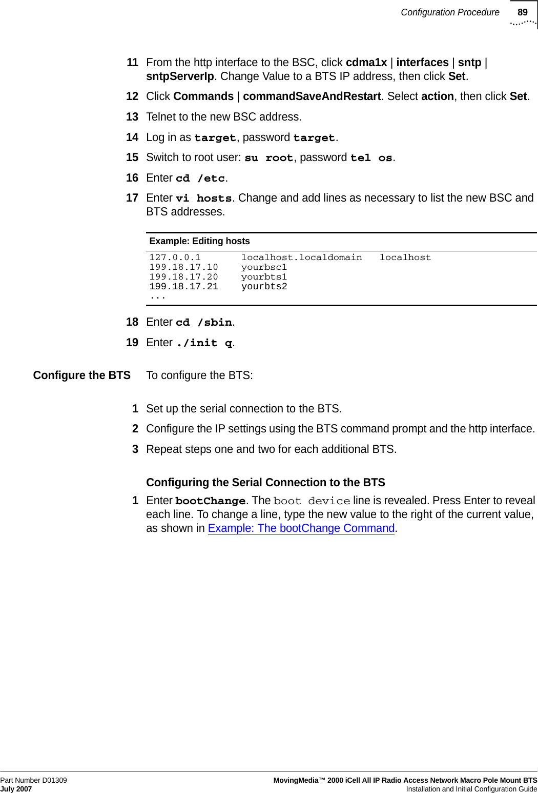
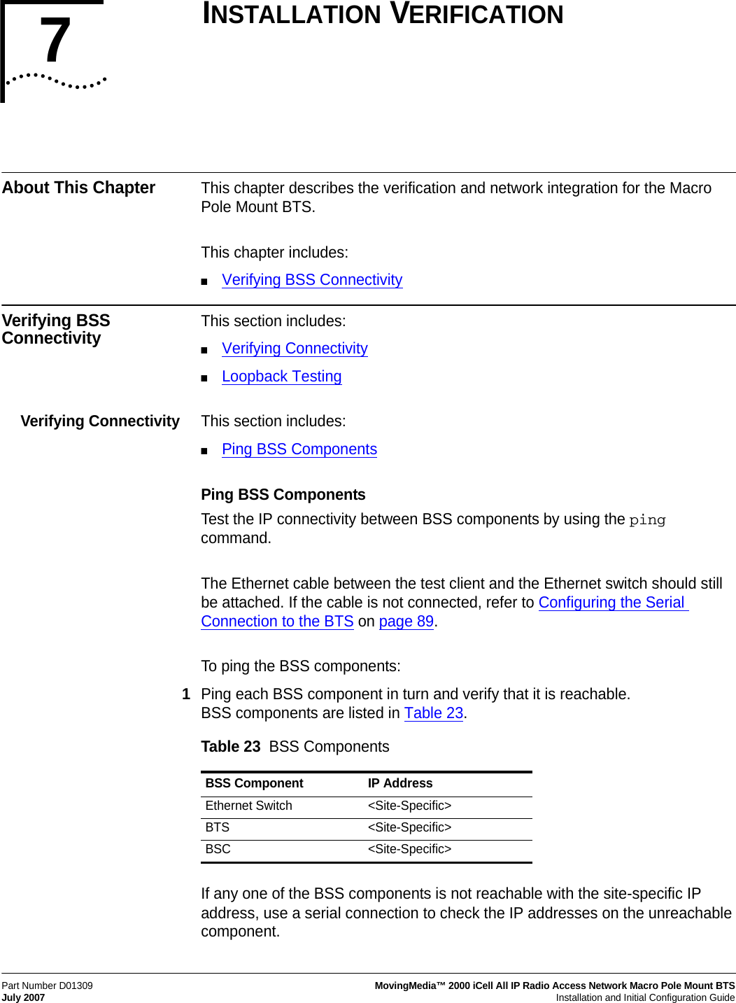
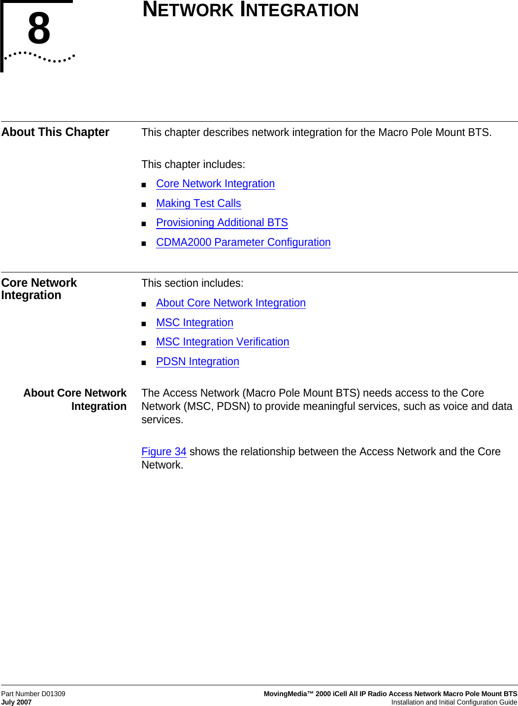
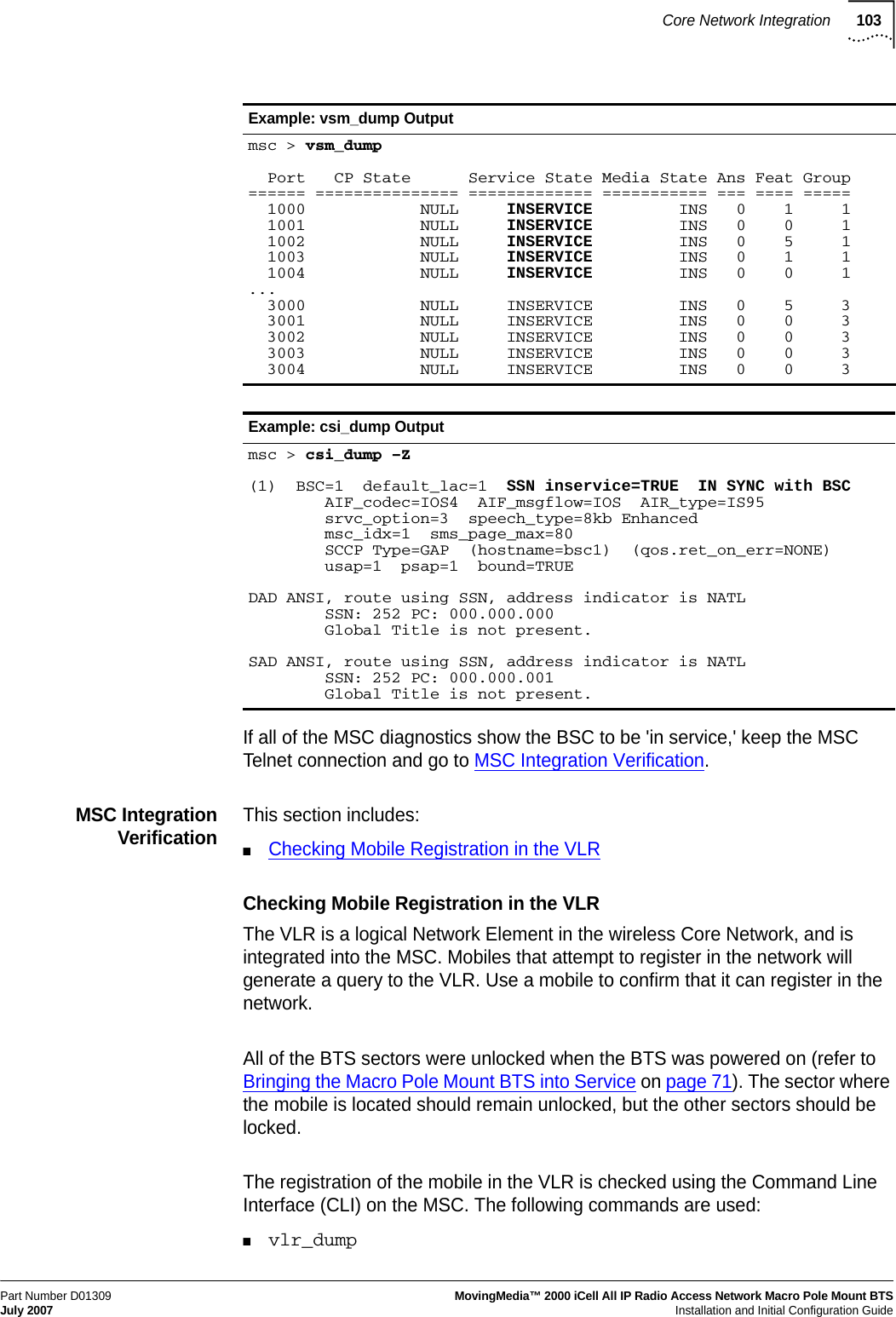
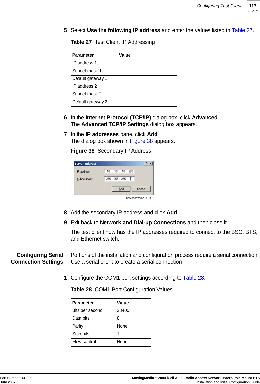
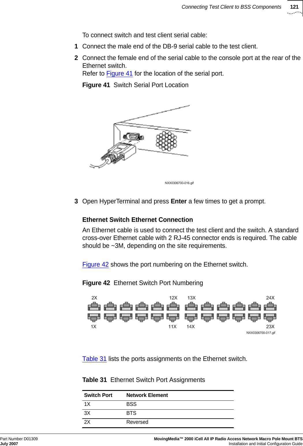
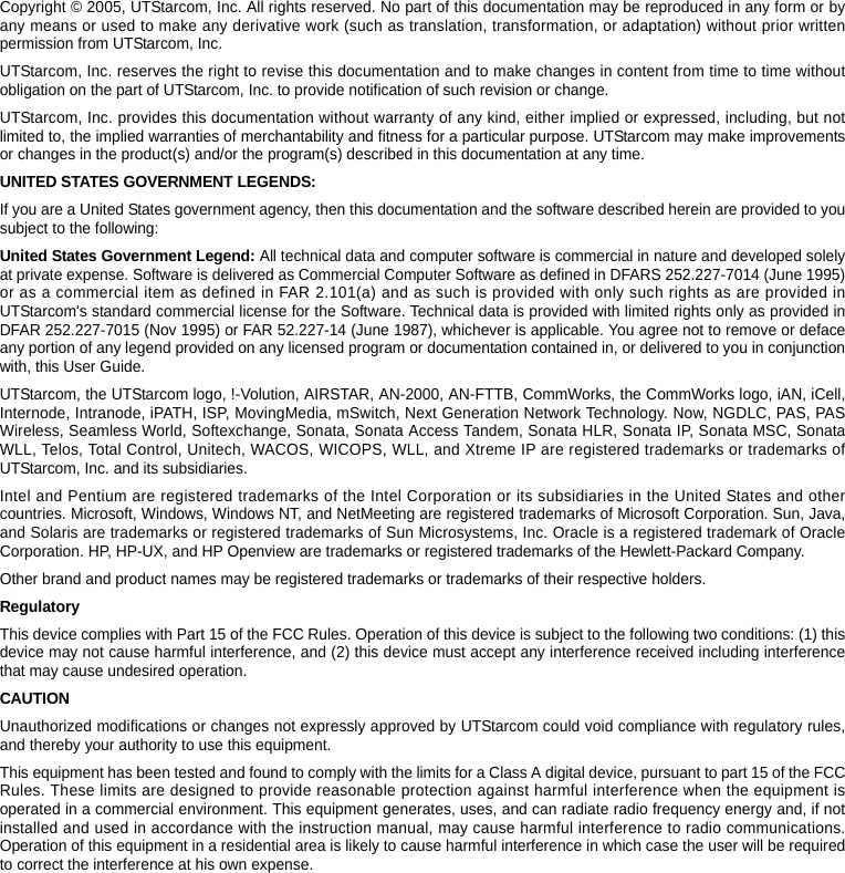
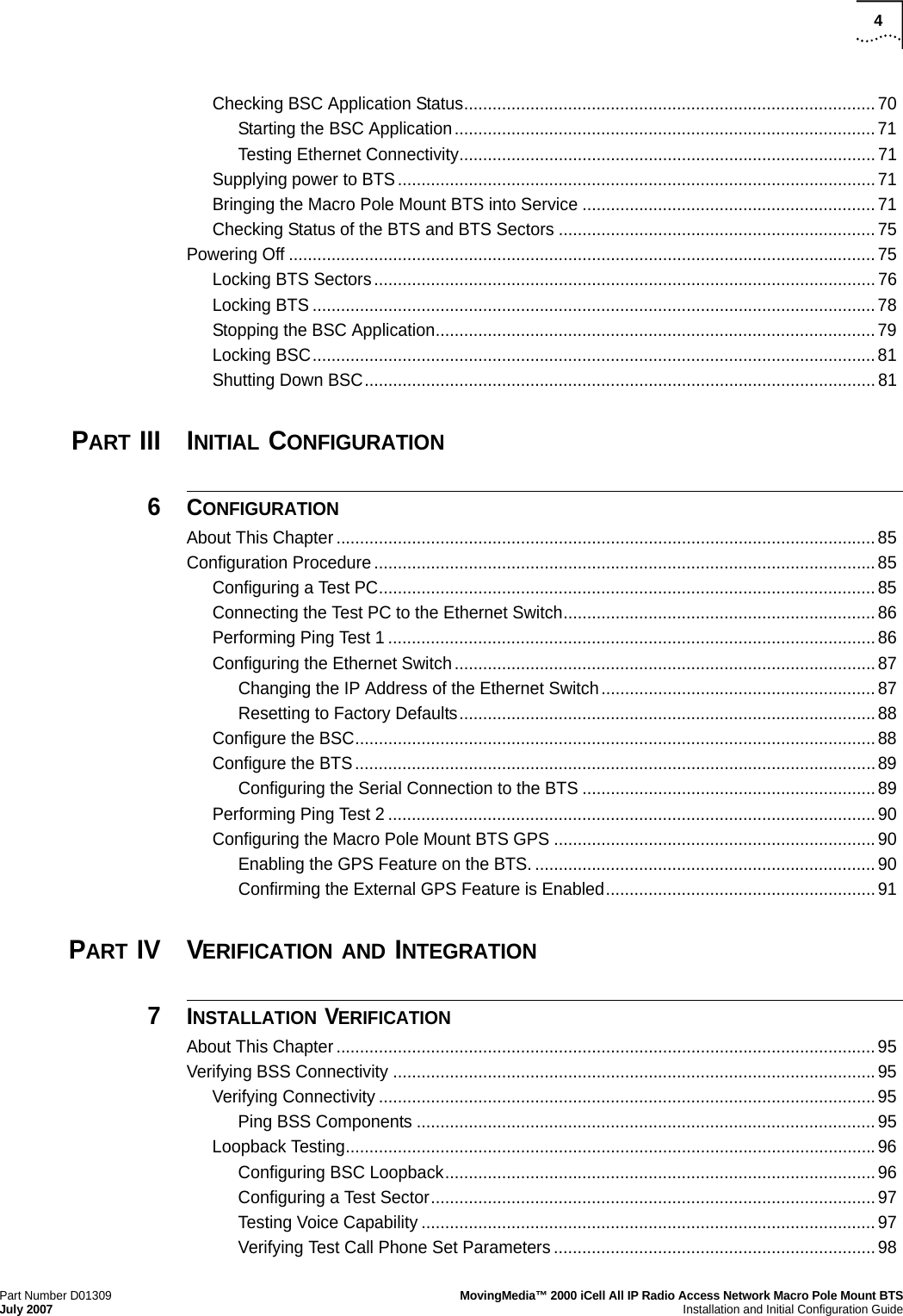
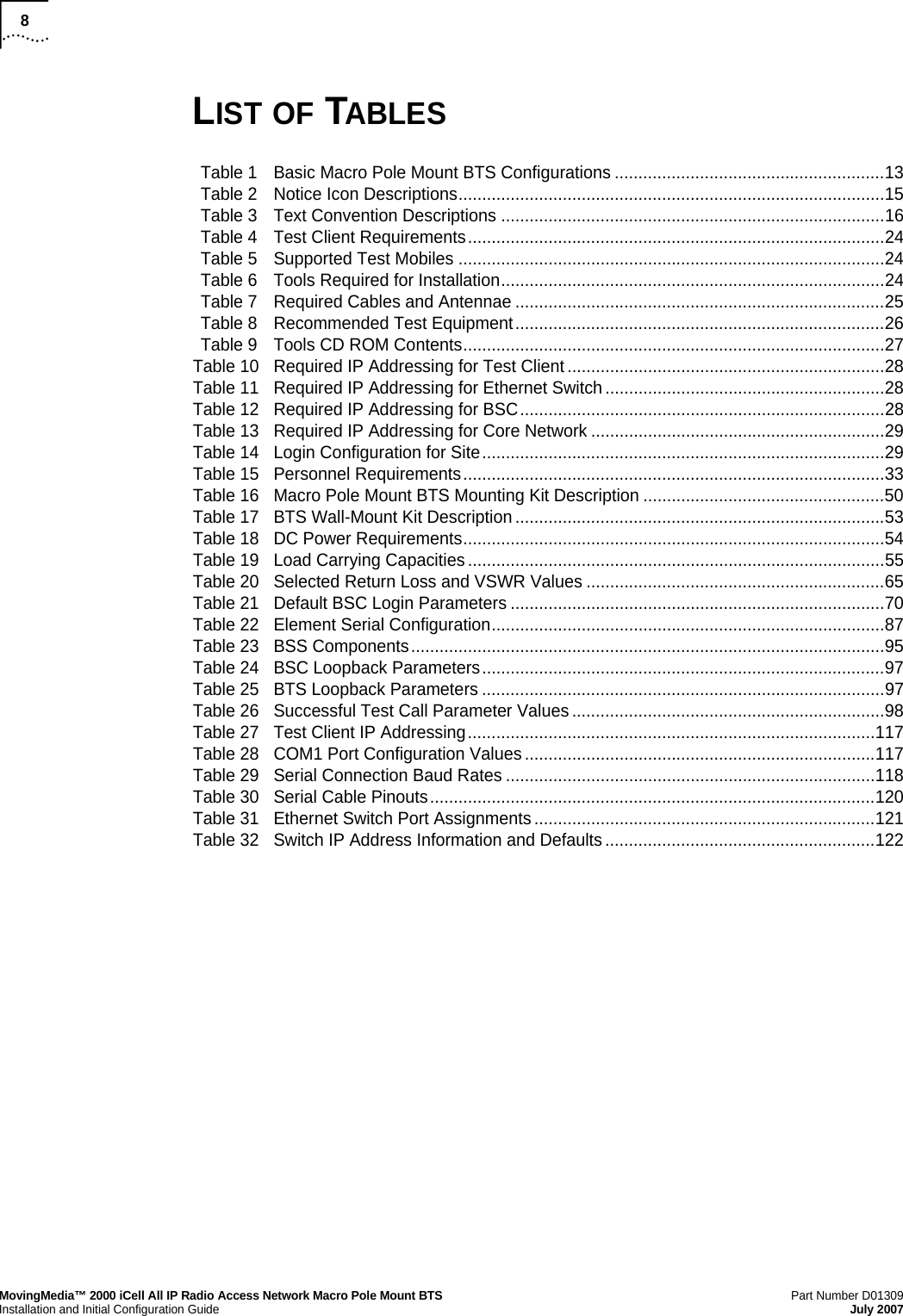
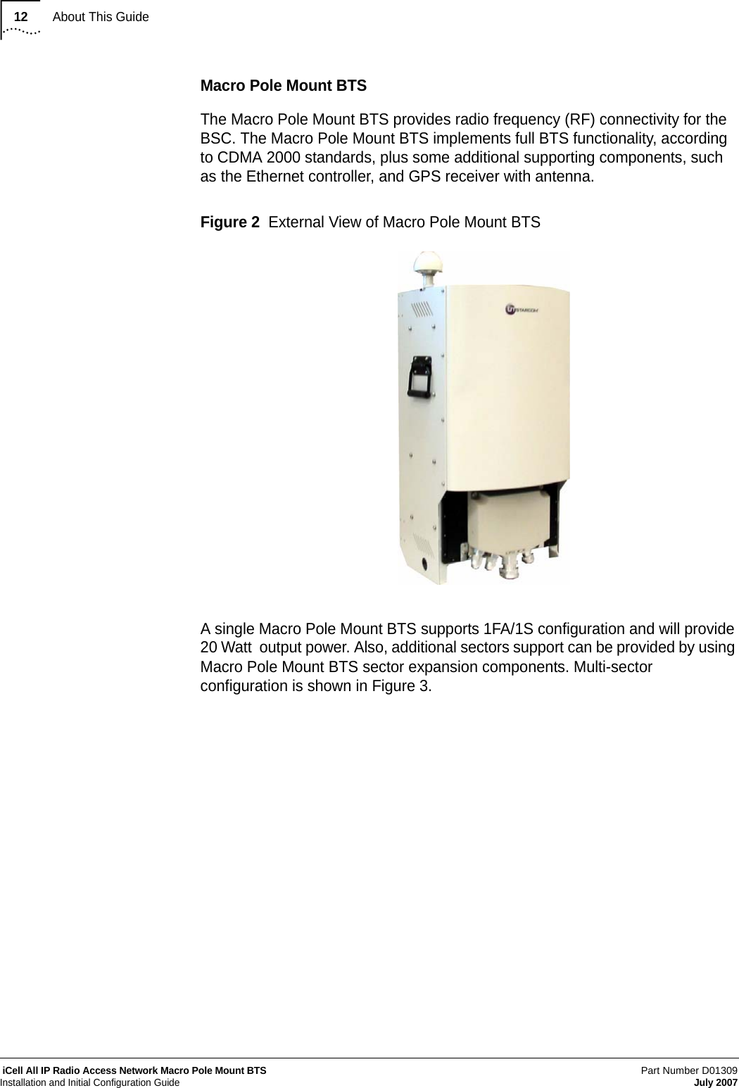
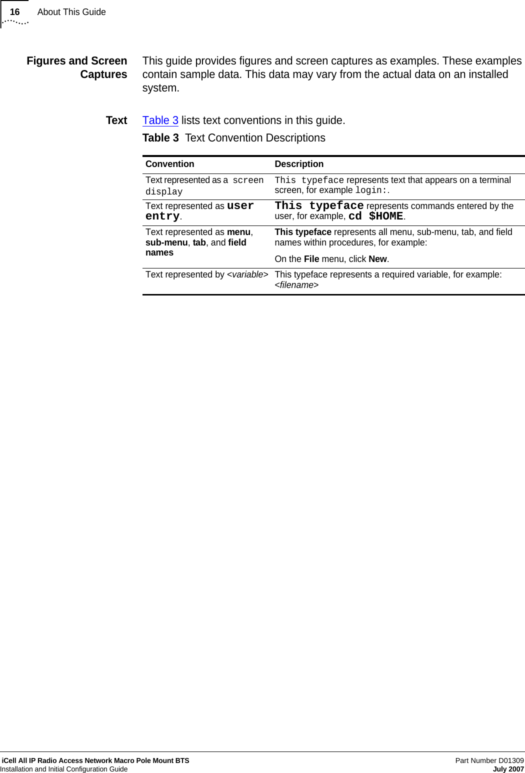
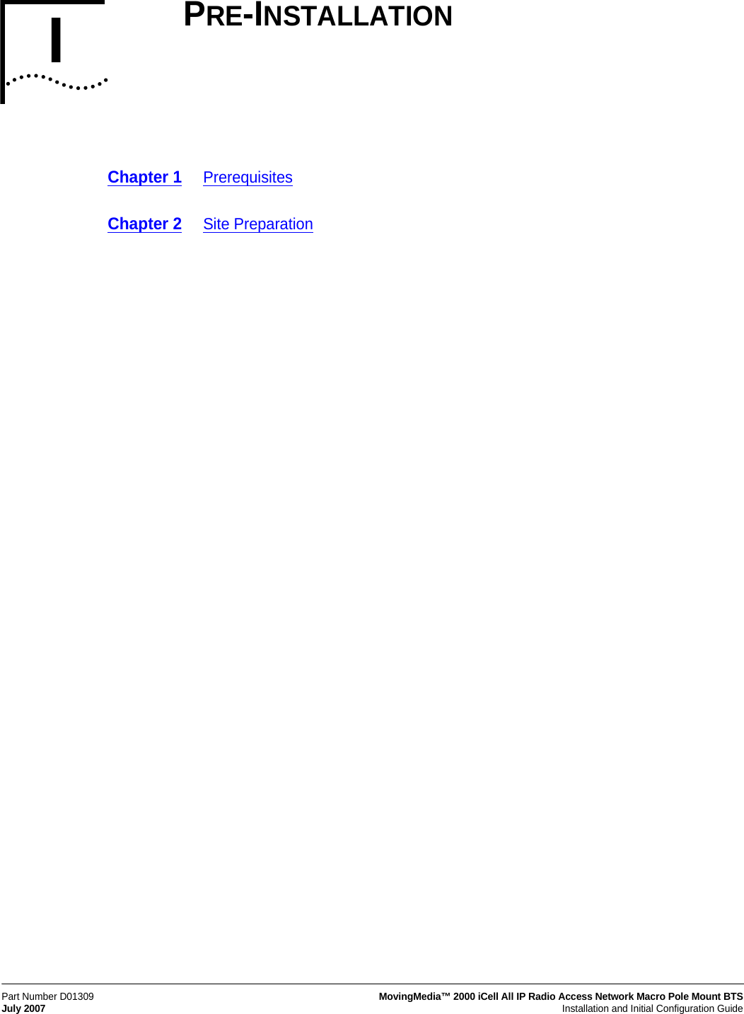
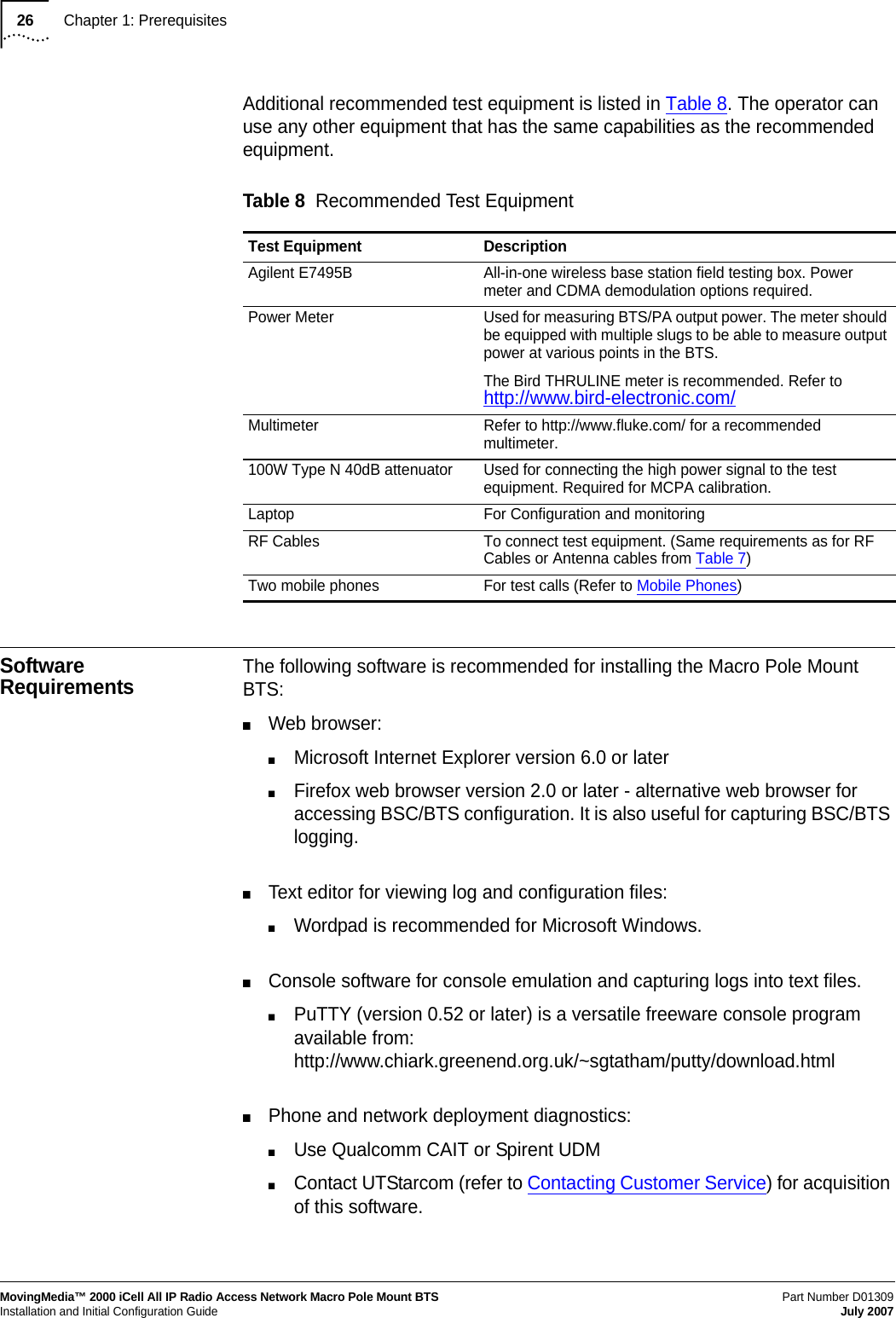
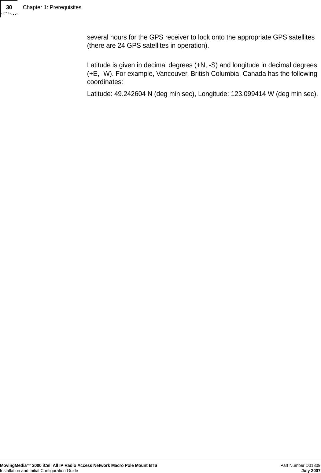
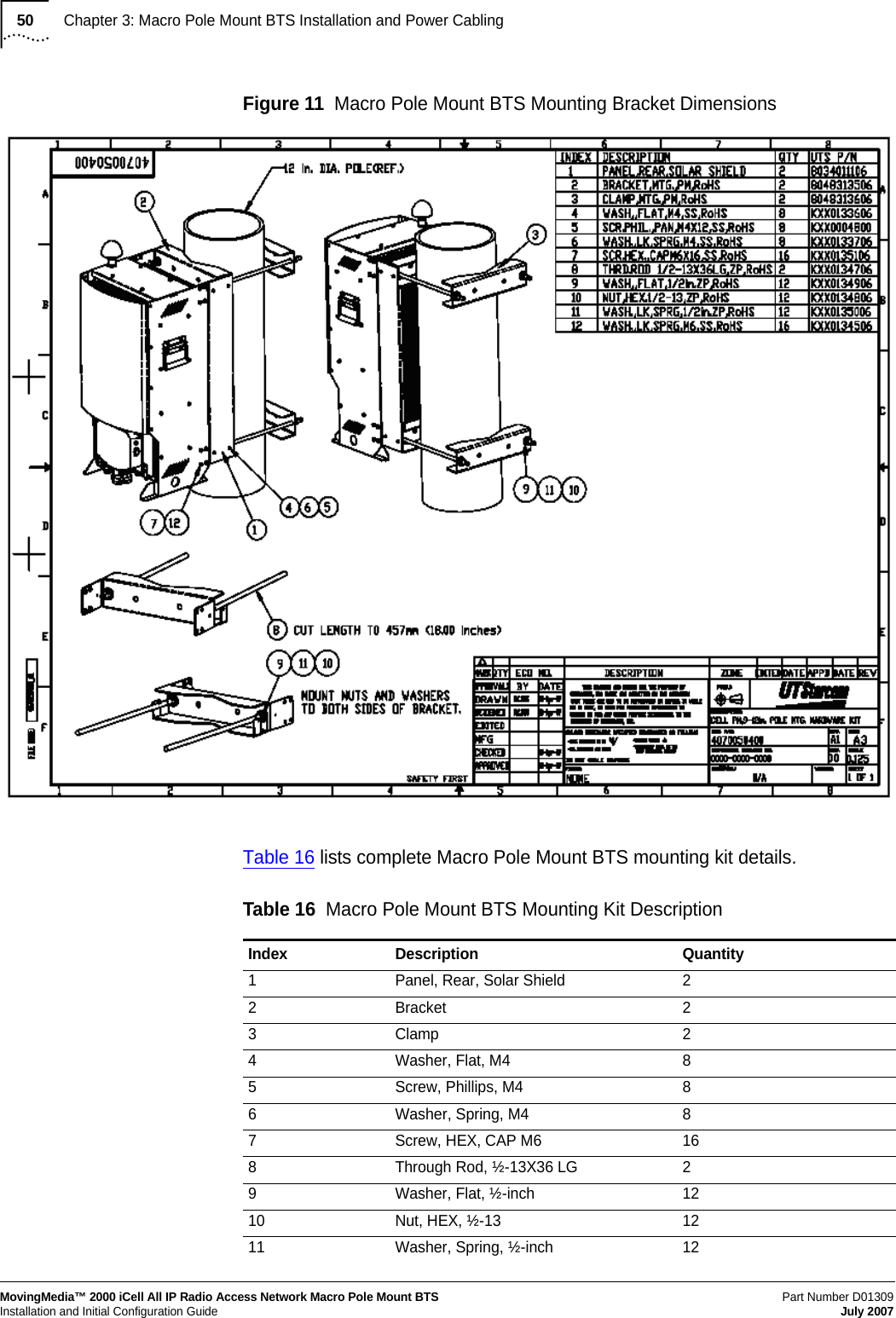
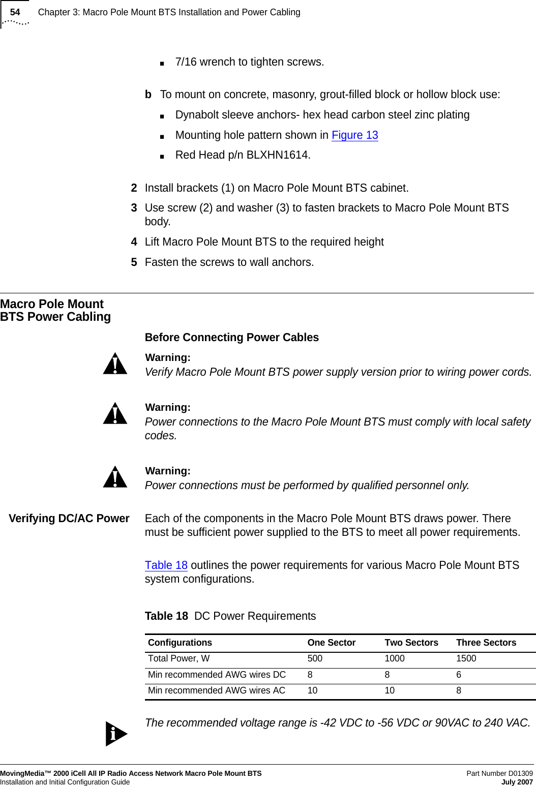
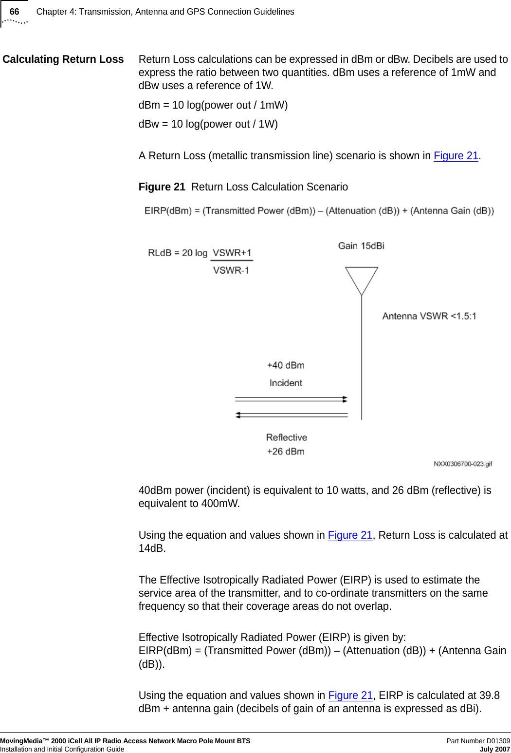
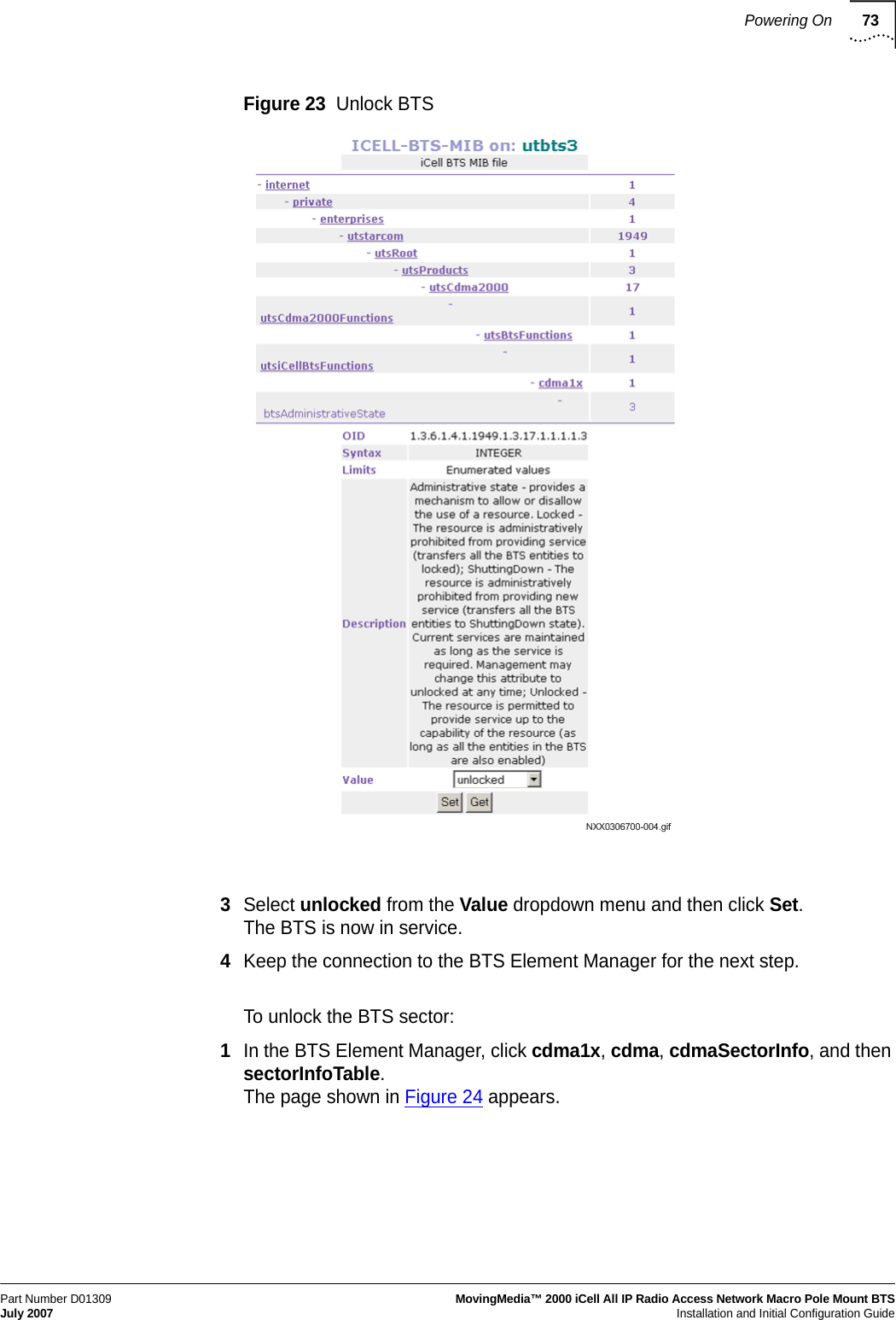
![Powering On71Part Number D01309MovingMedia™ 2000 iCell All IP Radio Access Network Macro Pole Mount BTS July 2007Installation and Initial Configuration GuideThe BSC application should display started. Refer to Example: BSC Application Status Check Session for an example Session.If the BSC application is not started, then start it as described in Starting the BSC Application.Starting the BSC ApplicationTo start the BSC application:1Connect and login to the BSC. Refer to Connecting to the BSC.2Start the application[icell@bsc7 icell]$ icell_bsc startCheck that the application is started [icell@bsc7 icell]$icell_bsc statusTesting Ethernet ConnectivityTo test Ethernet connectivity:1Test IP connectivity between the test client and the BSC and BTS.> ping <BSC IP Address>> ping <BTS IP Address>2Close any BSC or BTS Element Manager connections.Supplying power to BTS To supply power to the BTS:1Make sure the power supply to the Macro Pole Mount BTS is ON.2Confirm visually that the power indicator on each Macro Pole Mount BTS power supply is lit.3Wait approximately one minute for the BTS to complete the boot process.Bringing the Macro Pole Mount BTS into Service The Macro Pole Mount BTS is brought into service by unlocking the BSC, BTS, and then each BTS sector. The Macro Pole Mount BTS is fully in service when all sectors have blossomed.Example: BSC Application Status Check SessionRed Hat Linux release 8.0 (Psyche)Kernel 2.4.18-14 on an i686login: icellPassword: Last login: Mon Jan 27 12:19:20 from 10.10.1.13[icell@bsc7 icell]$icell_bsc statusStatus bsc_lxrel: started2185921864[icell@bsc7 icell]$](https://usermanual.wiki/Star-Solutions/1-05-00-02-1/User-Guide-847688-Page-73.png)
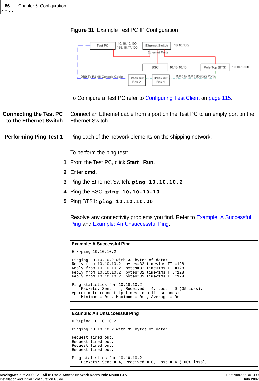
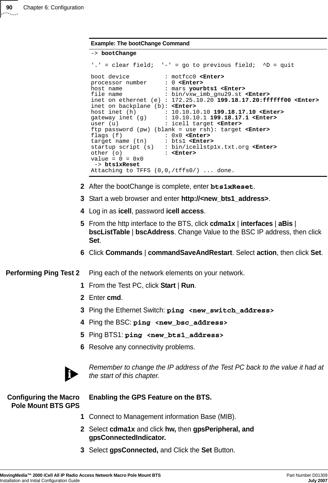
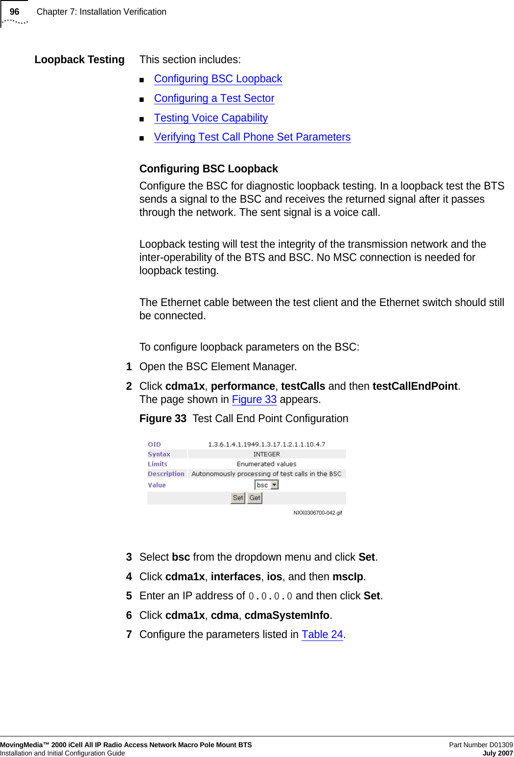
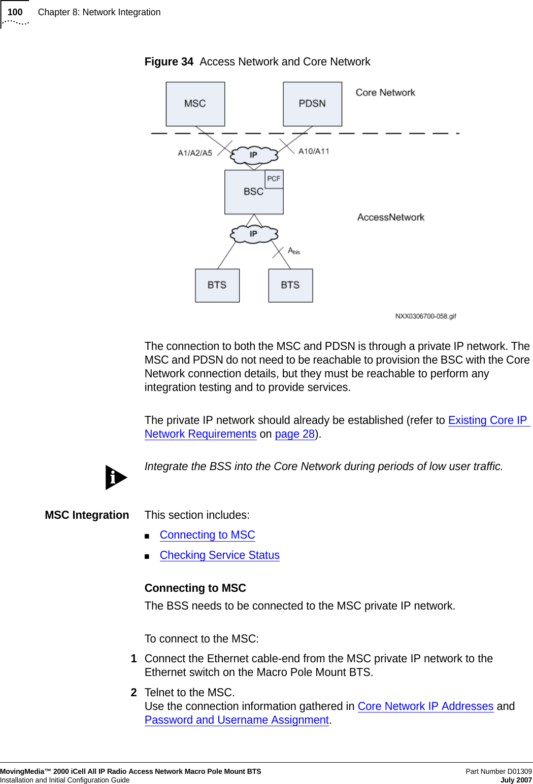
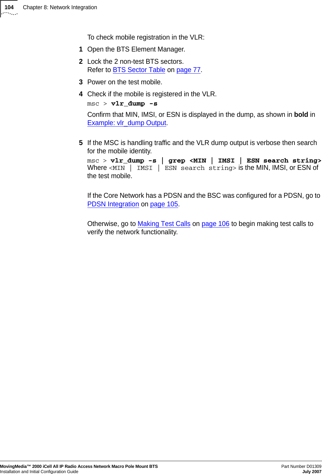
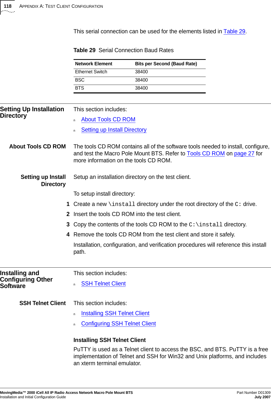
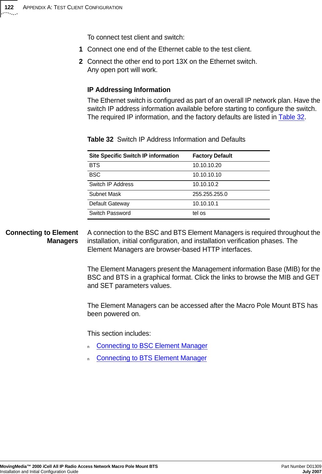
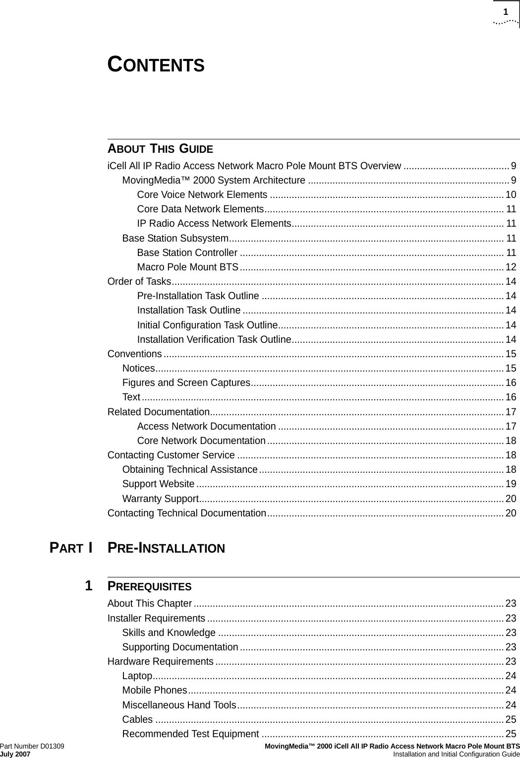
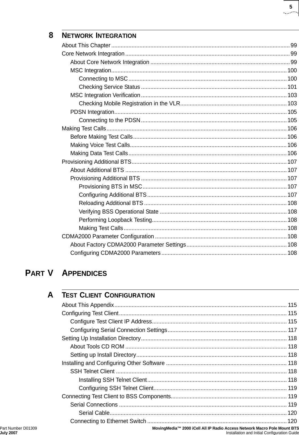
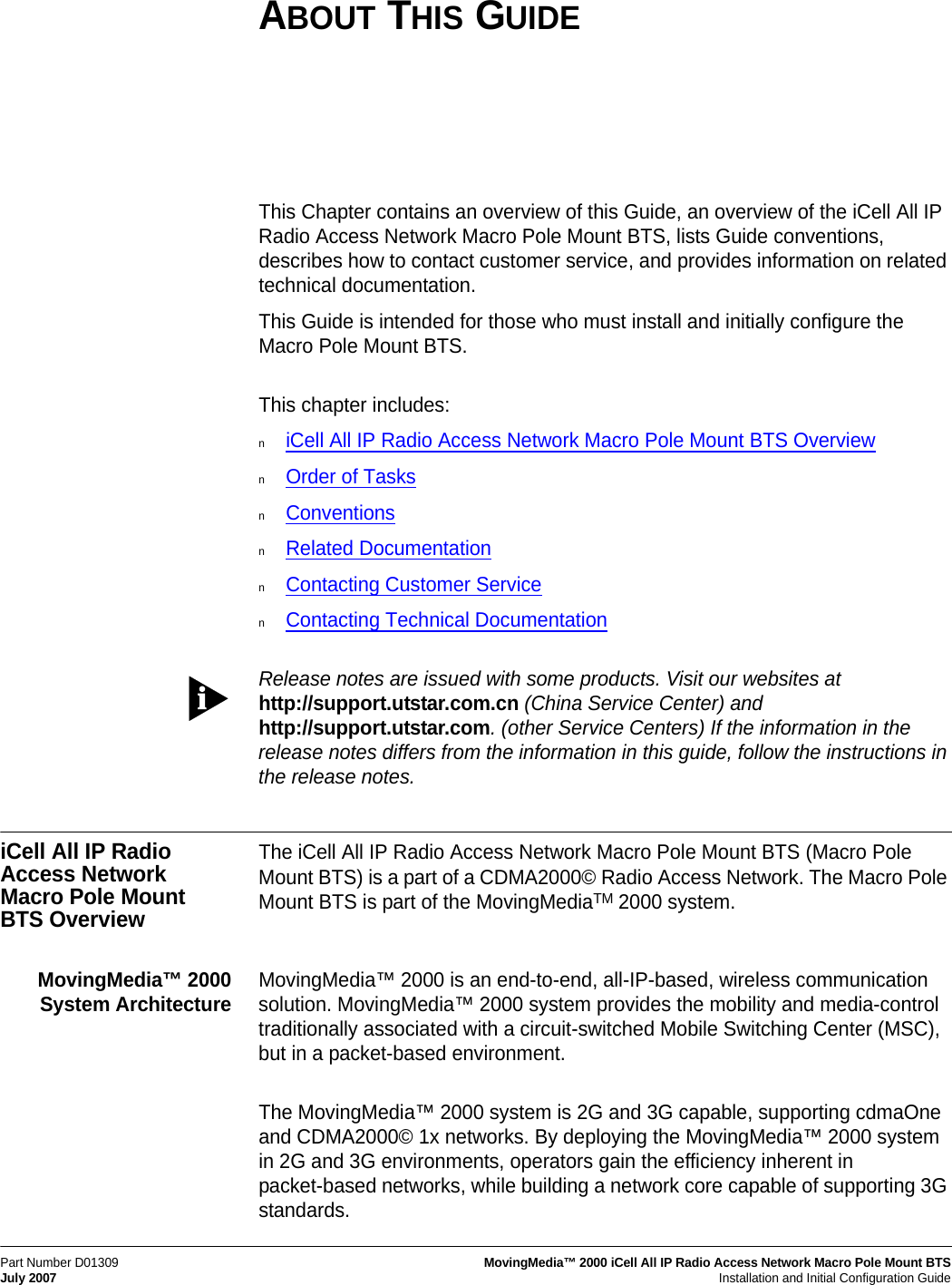
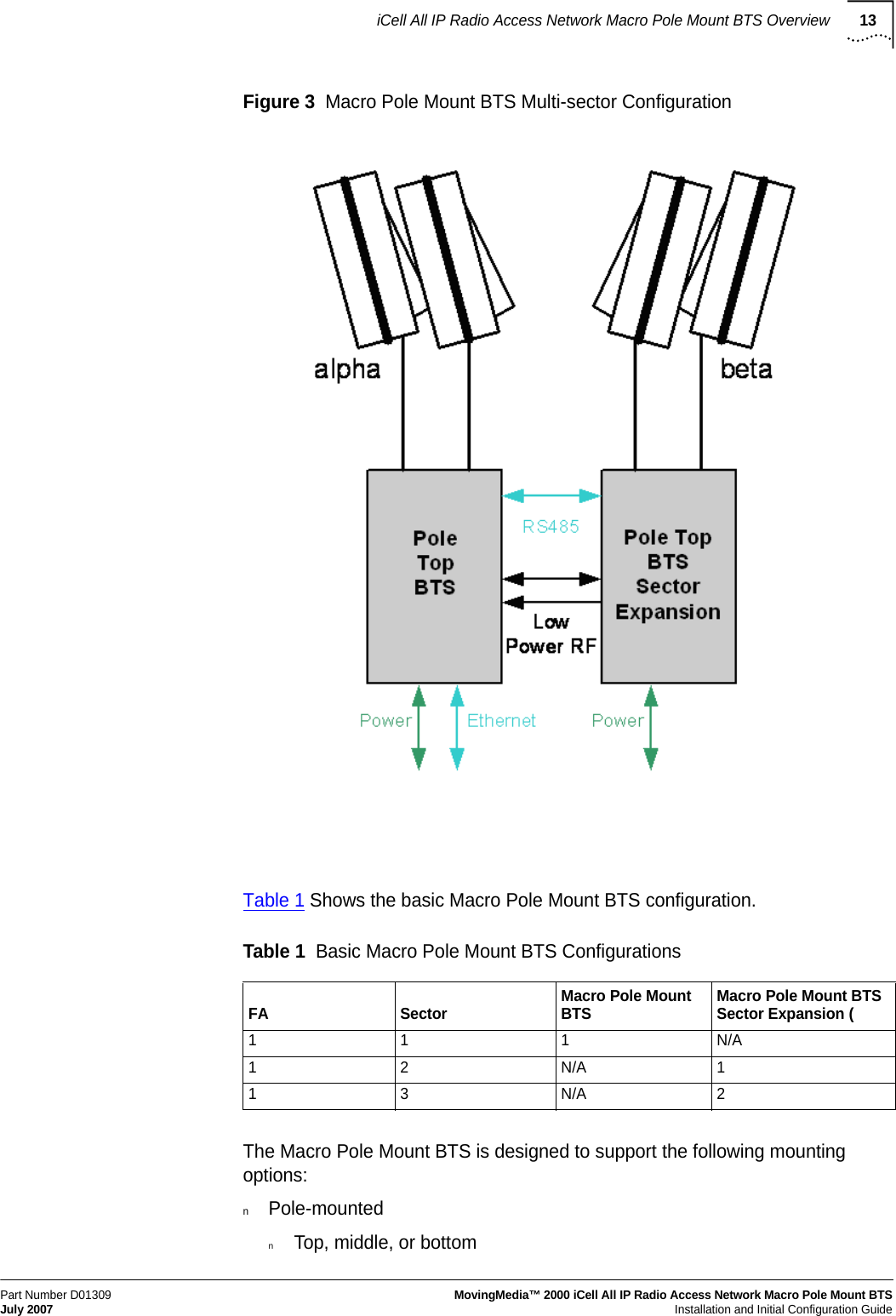
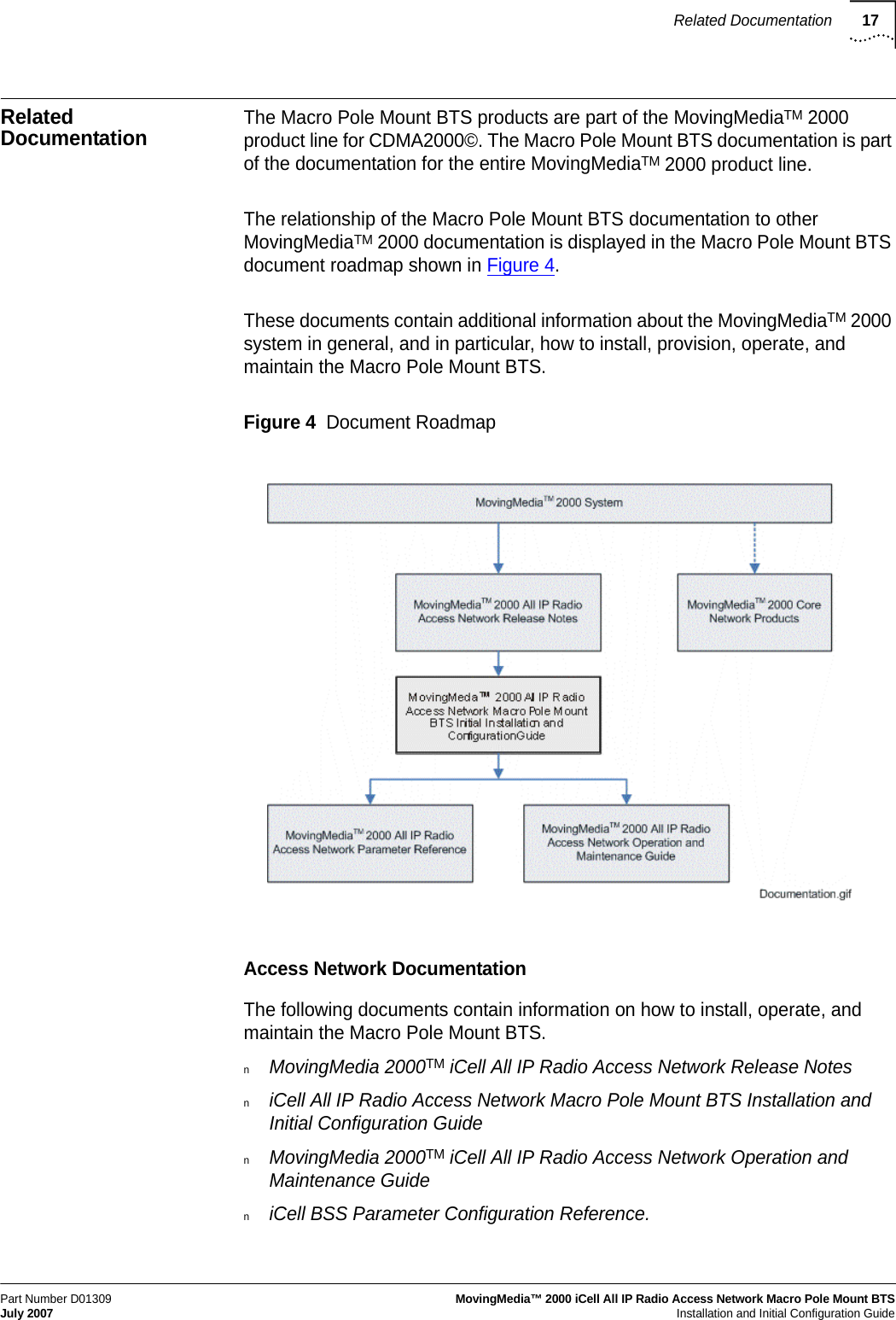
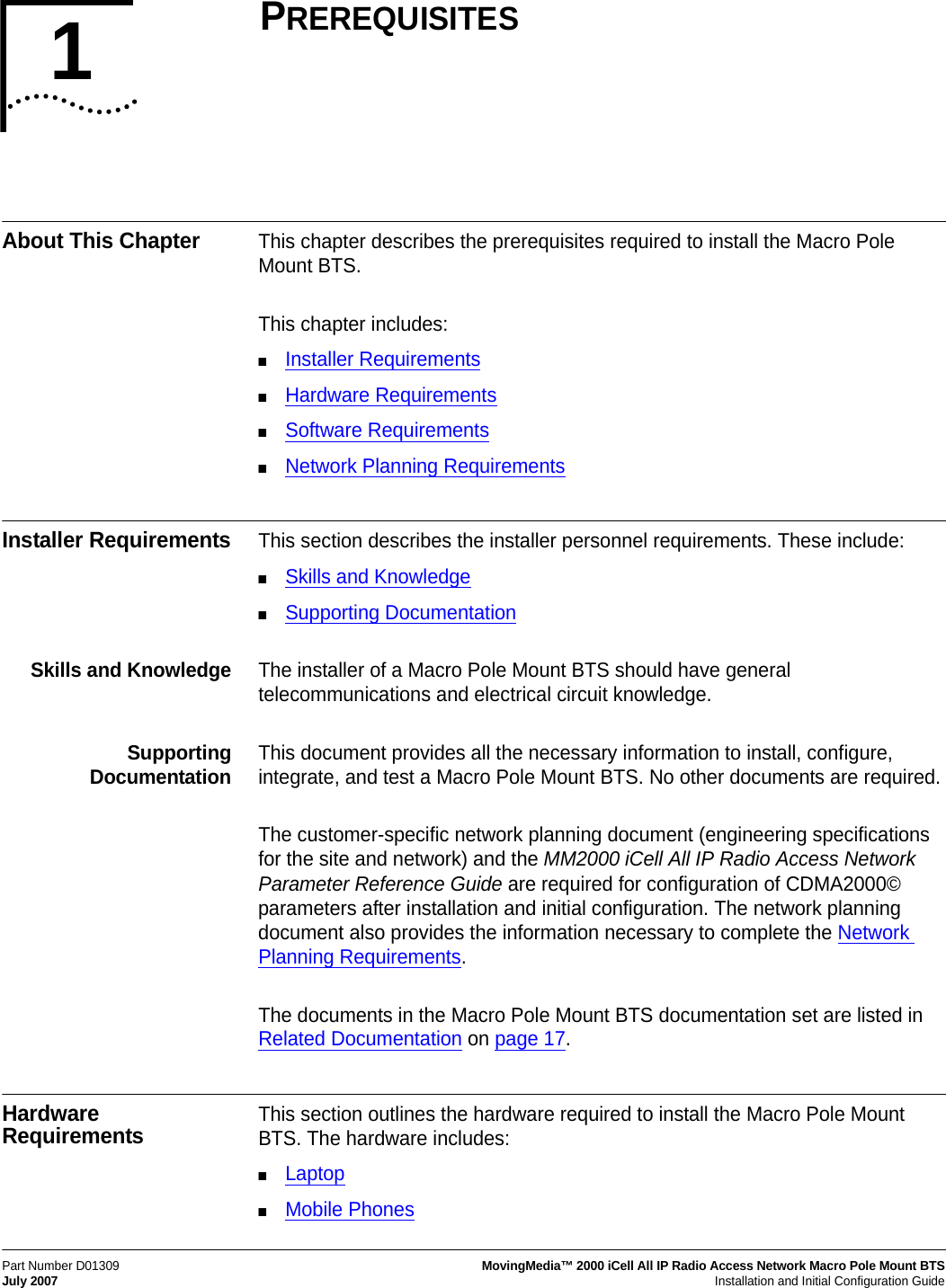
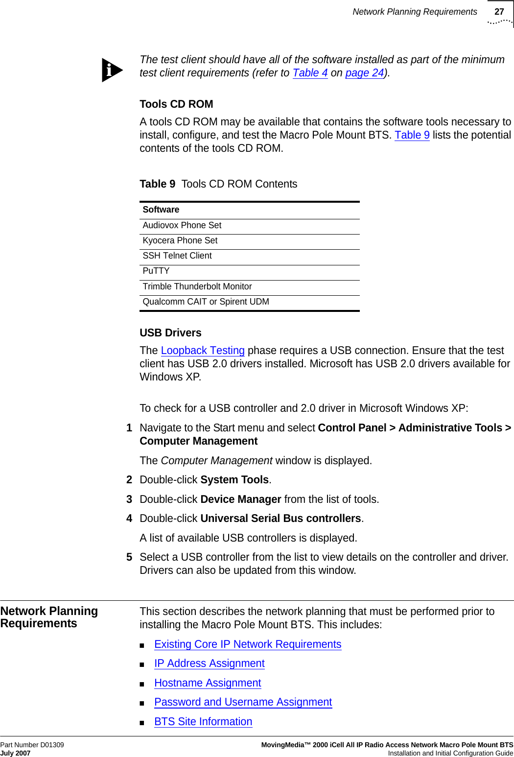
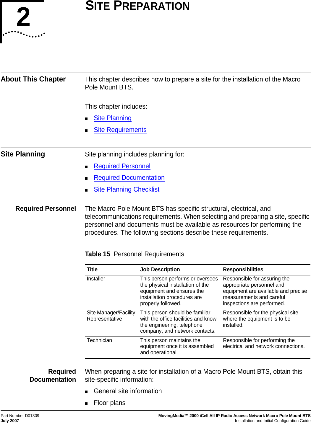
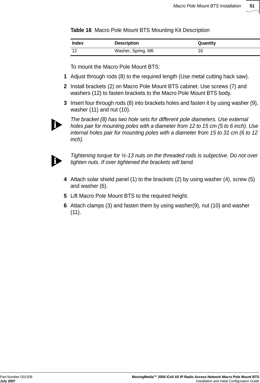
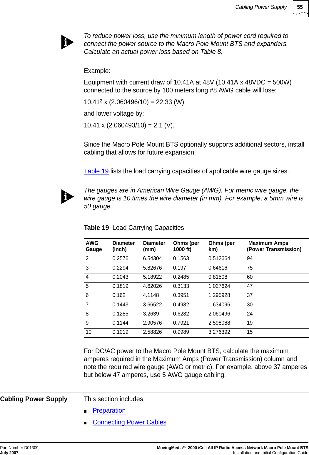
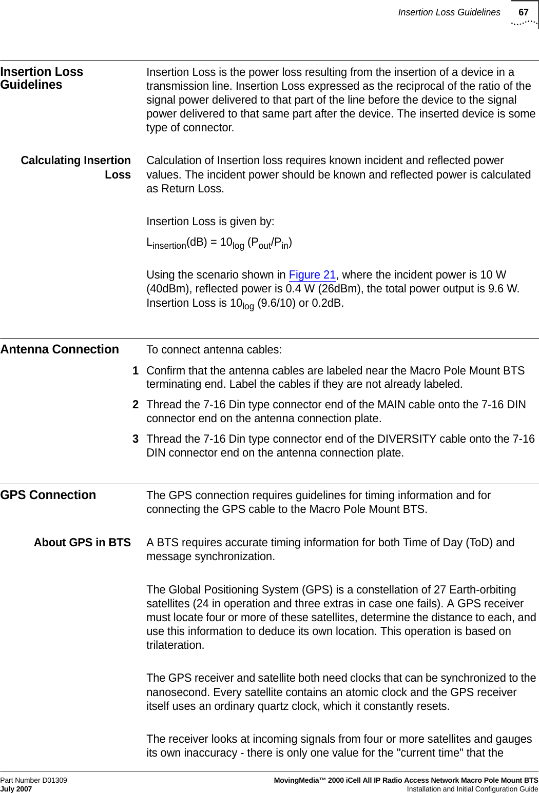
![Powering Off79Part Number D01309MovingMedia™ 2000 iCell All IP Radio Access Network Macro Pole Mount BTS July 2007Installation and Initial Configuration GuideFigure 28 Lock BTS2Select Locked from the dropdown menu and then click Set. The BTS is now out of service.3Exit the BTS Element Manager.Stopping the BSC ApplicationTo stop the BSC application:1Connect and login to the BSC. Refer to Connecting to the BSC on page 69.2Stop BSC application[icell@bsc7 icell]$ icell_bsc stop3Confirm that BSC application is stopped.[icell@bsc7 icell]$ icell_bsc status4Keep the Telnet session open for a further procedure.](https://usermanual.wiki/Star-Solutions/1-05-00-02-1/User-Guide-847688-Page-81.png)
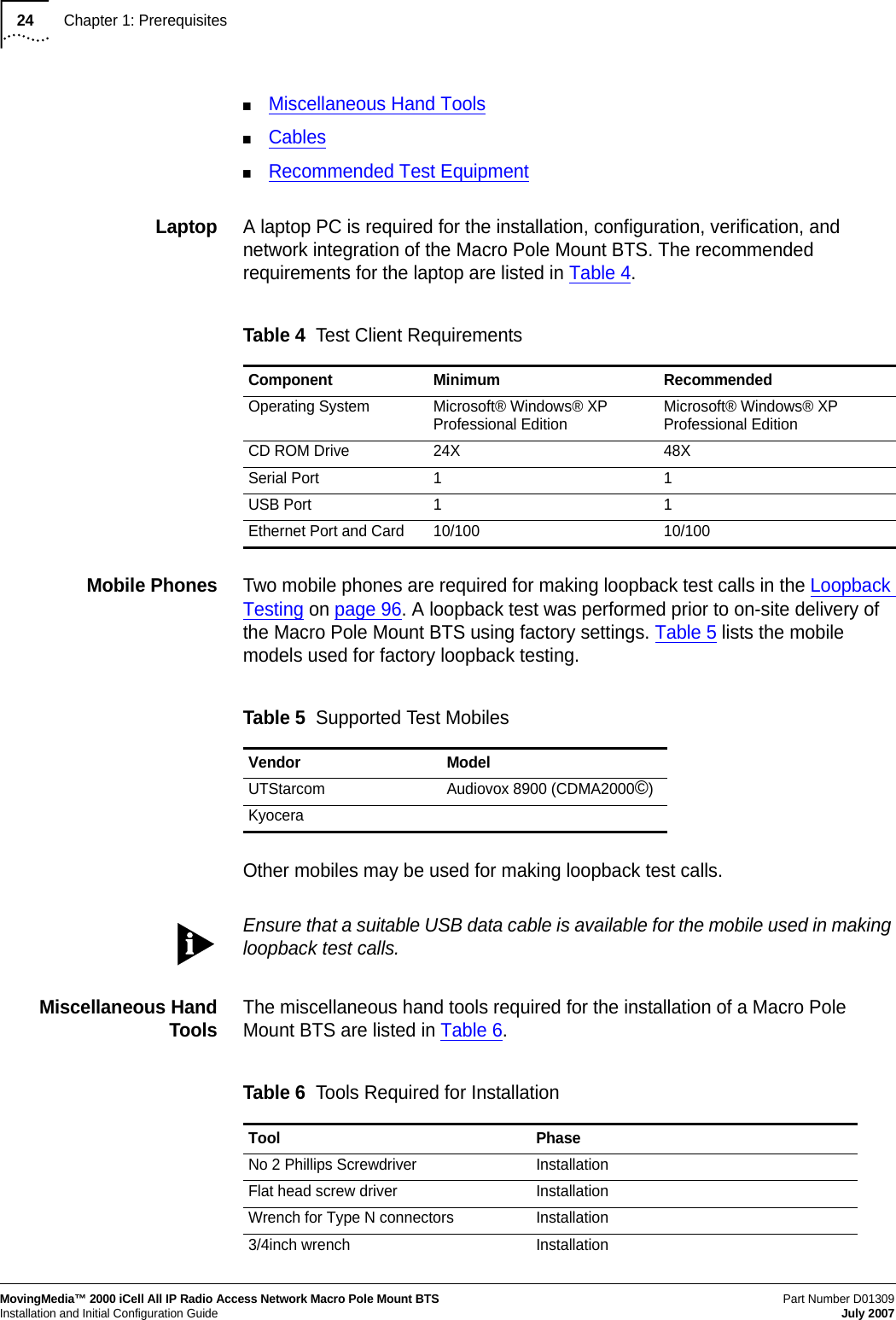
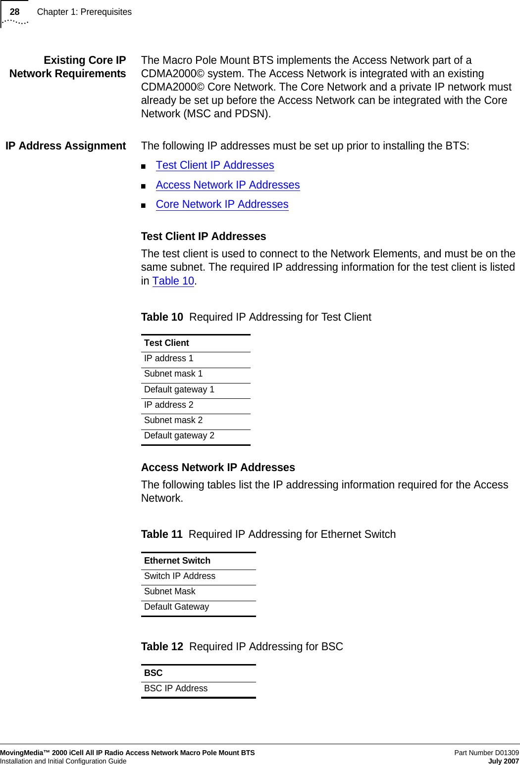
![80Chapter 5: Powering On and OffMovingMedia™ 2000 iCell All IP Radio Access Network Macro Pole Mount BTSPart Number D01309 Installation and Initial Configuration Guide July 2007The application should be stopped. Refer to Example: Stop BSC Application for an example session.Example: Stop BSC ApplicationRed Hat Linux release 8.0 (Psyche)Kernel 2.4.18-14 on an i686login: icellPassword: Last login: Mon Jan 27 12:19:20 from 10.10.1.13 [icell@bsc7 icell]$ icell_bsc stopShutting down bsc_lxrel: ... [icell@bsc7 icell]$ icell_bsc statusStatus bsc_lxrel: stopped [icell@bsc7 icell]$](https://usermanual.wiki/Star-Solutions/1-05-00-02-1/User-Guide-847688-Page-82.png)
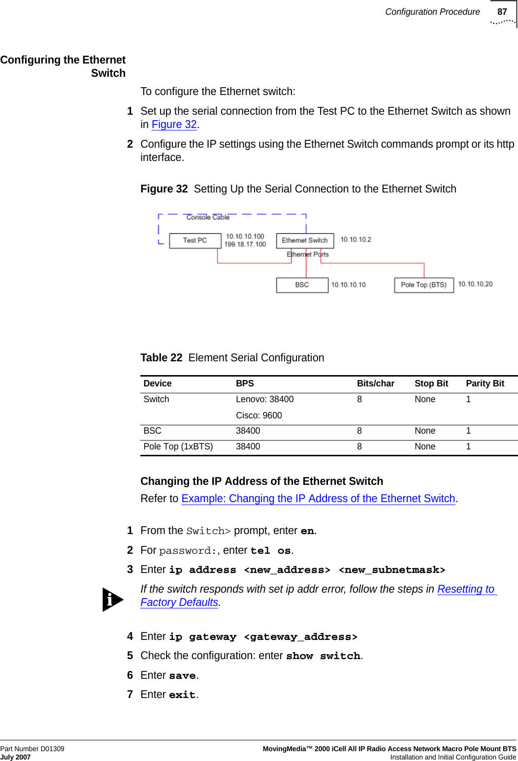
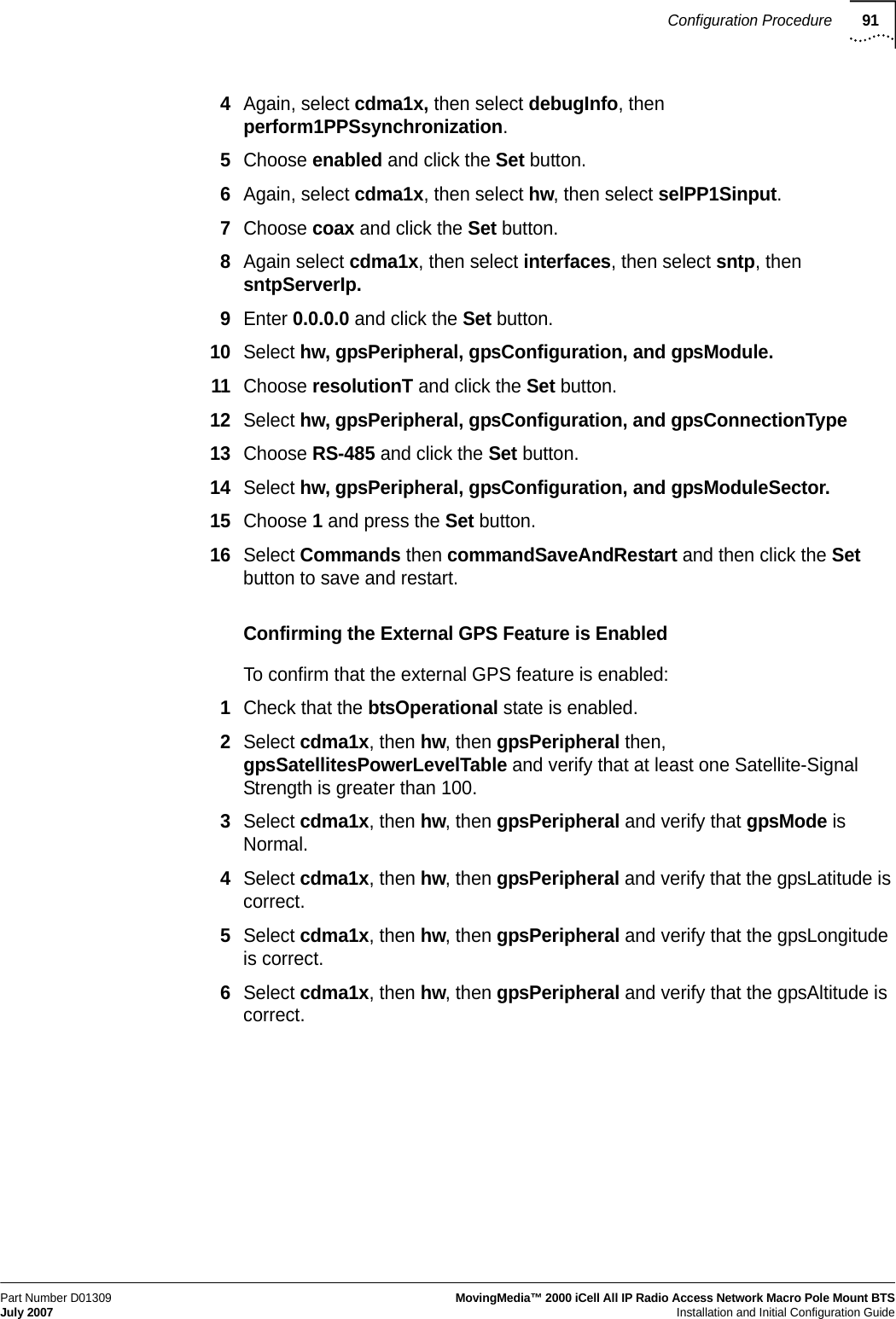
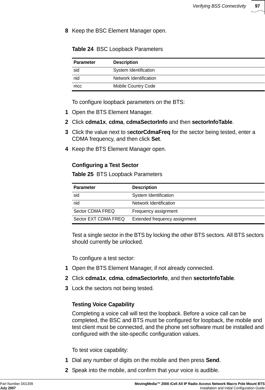
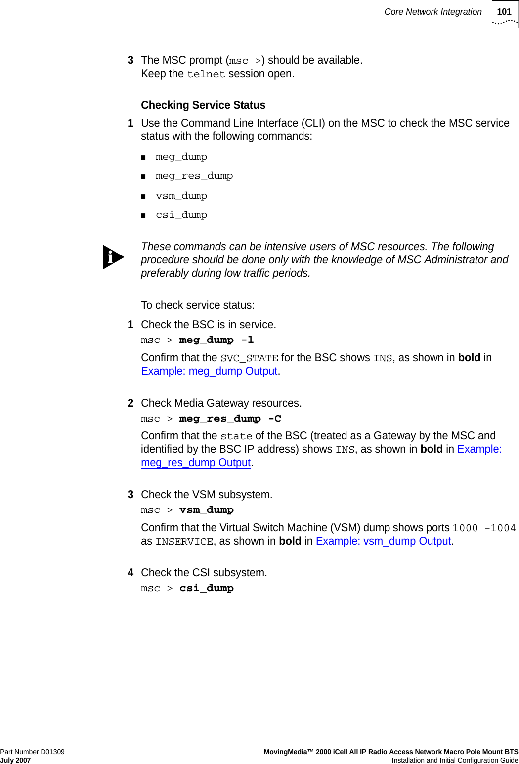
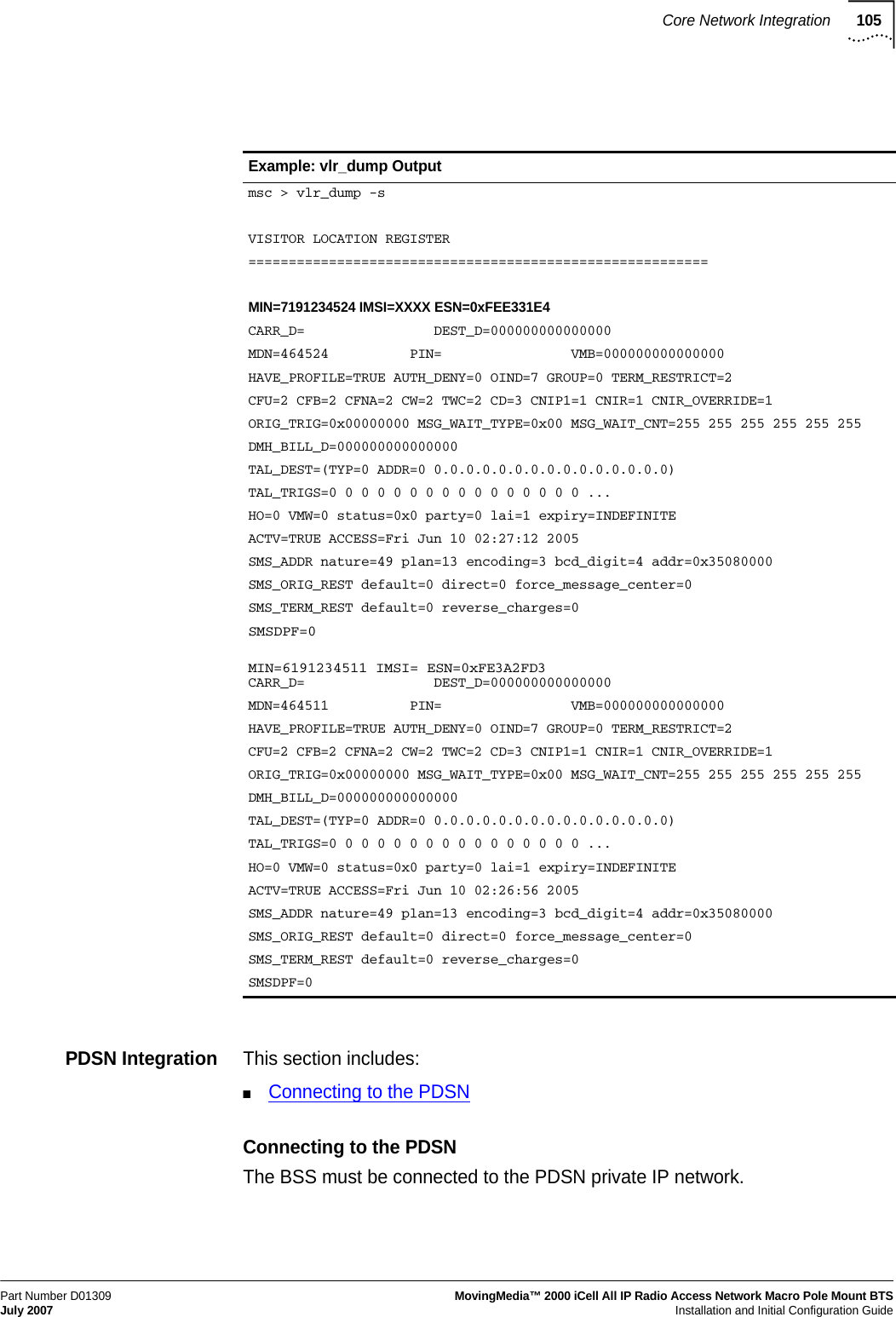
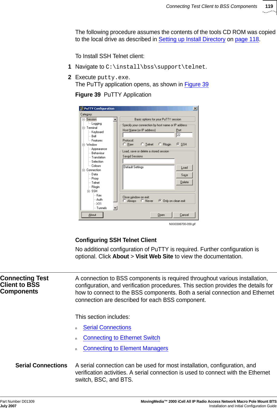
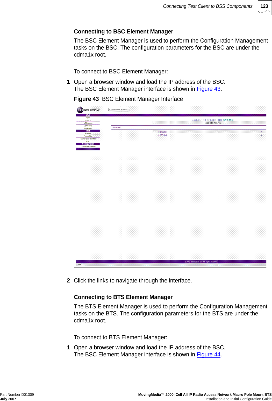
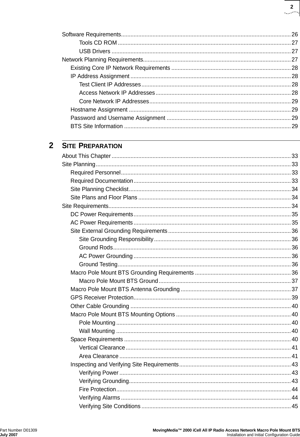
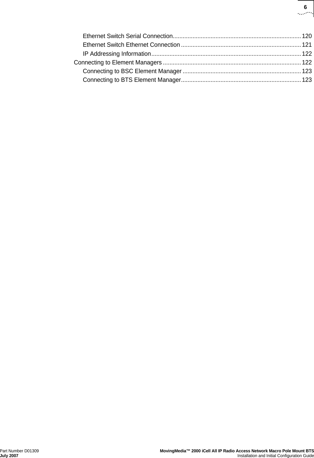
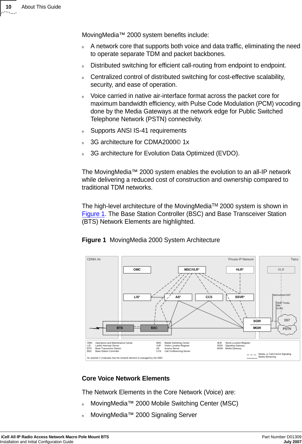
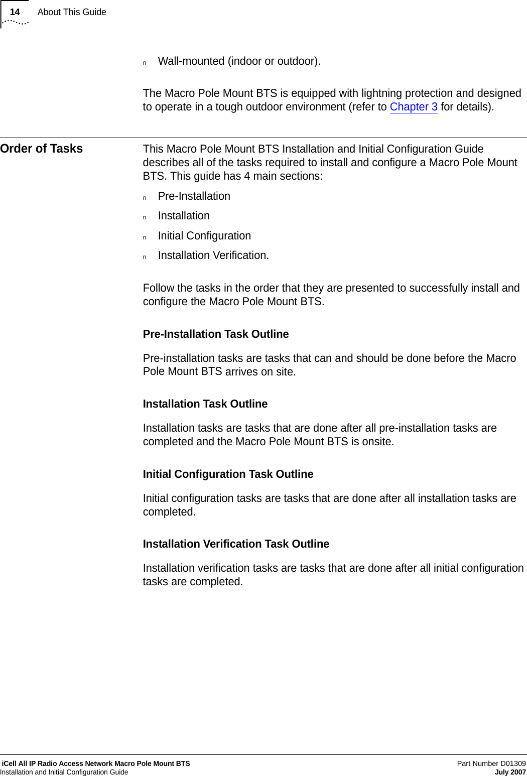
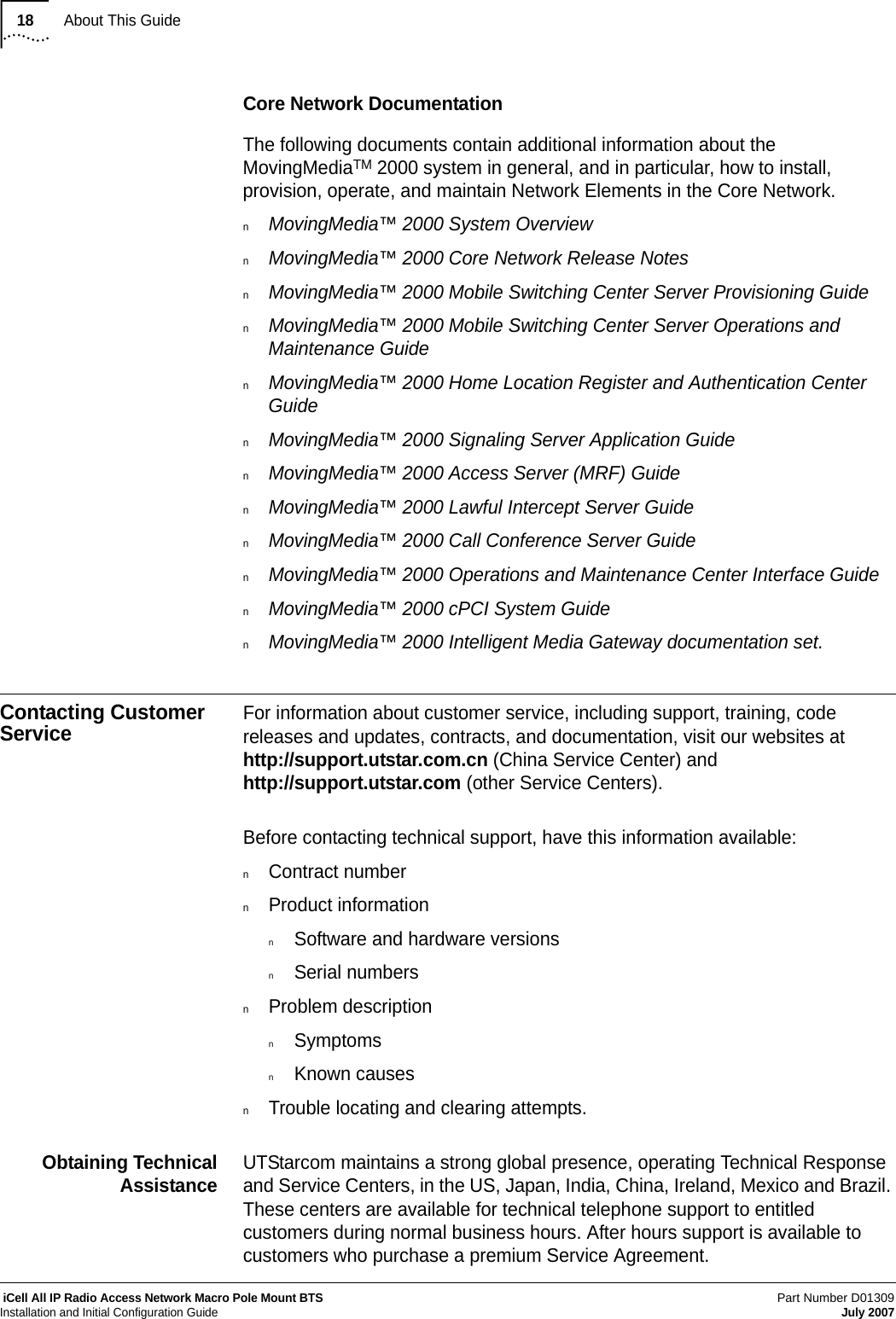
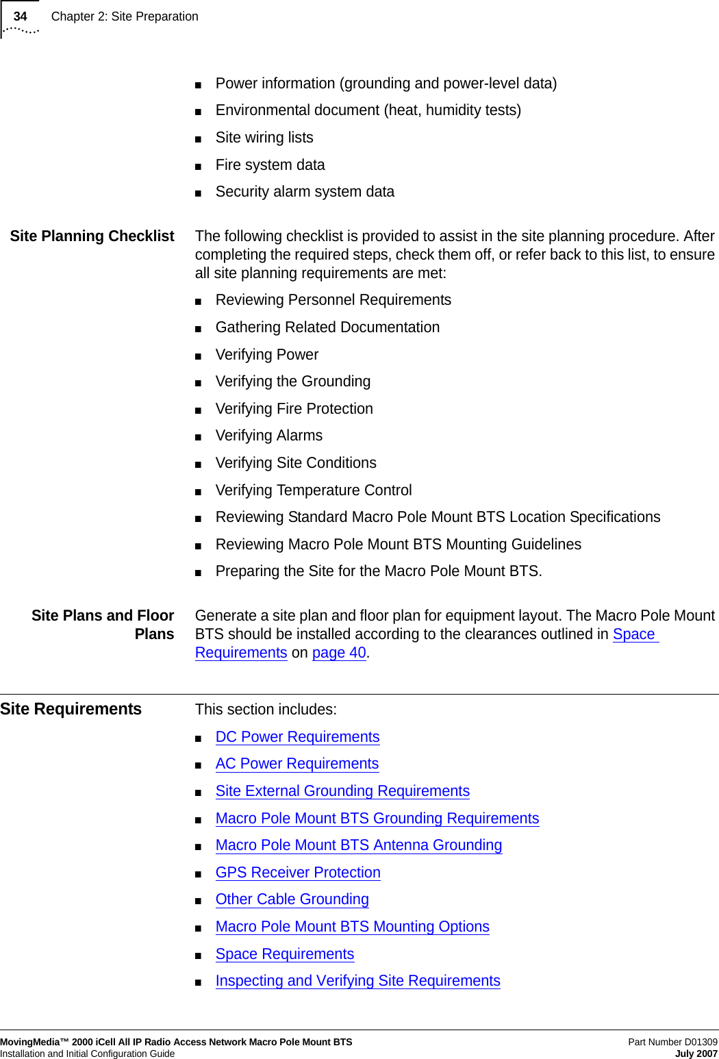
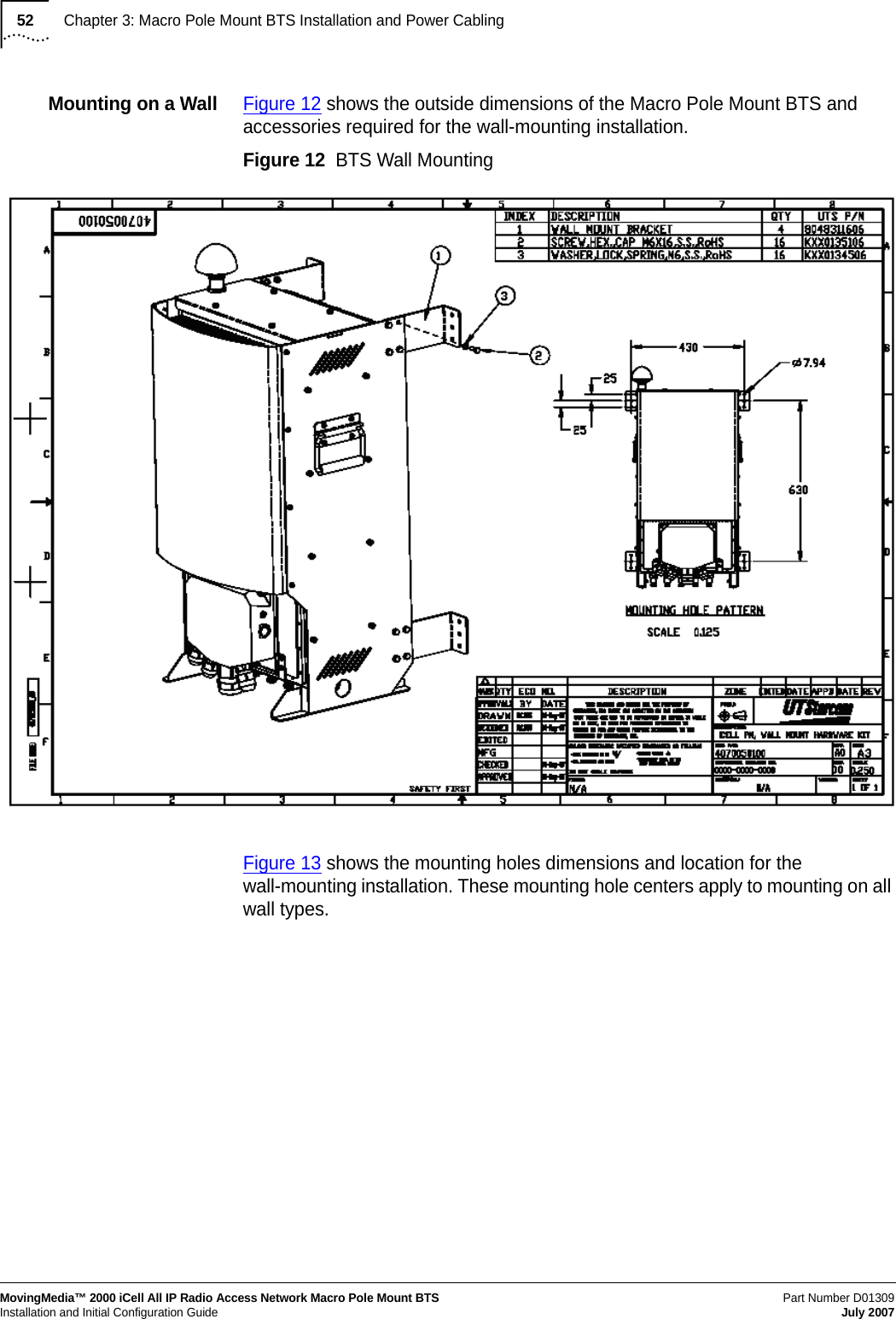
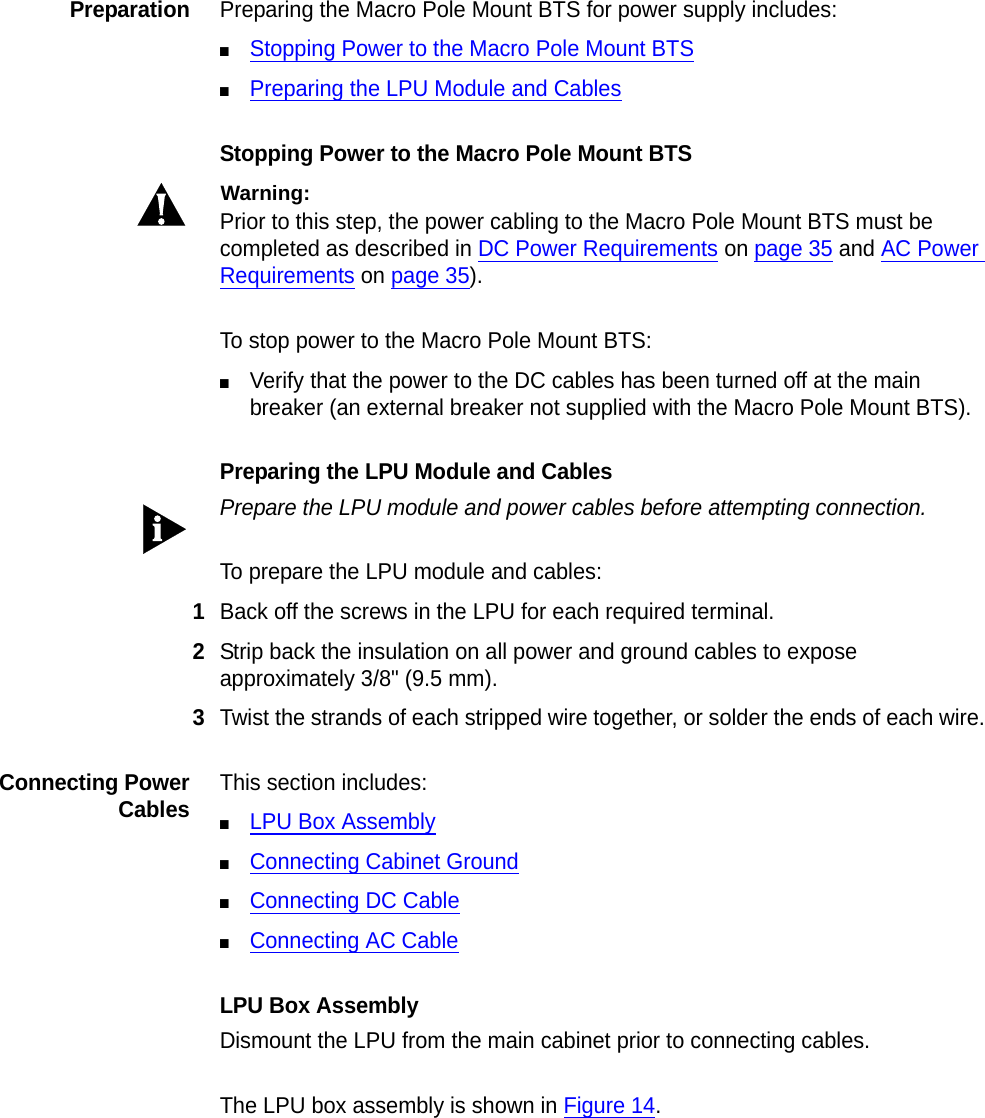
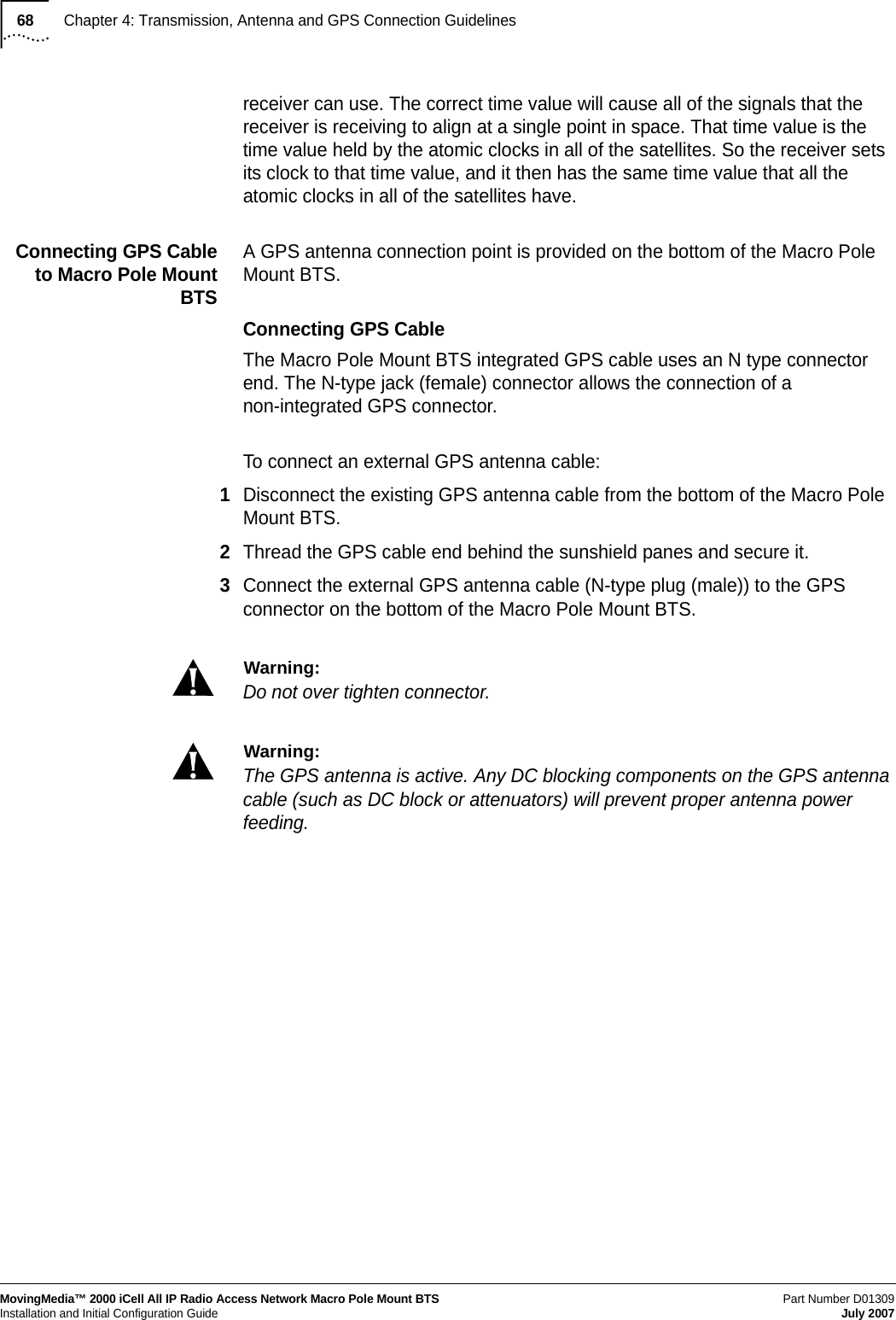
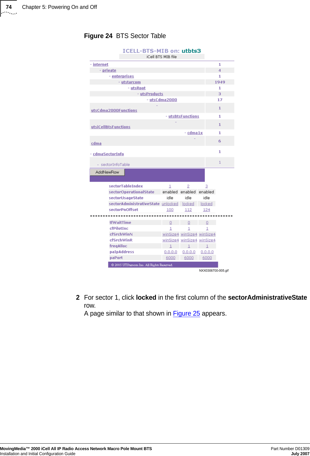
![Powering Off81Part Number D01309MovingMedia™ 2000 iCell All IP Radio Access Network Macro Pole Mount BTS July 2007Installation and Initial Configuration GuideLocking BSC Lock the BSC to take it out of service.To lock the BSC:1Connect to the BSC Element Manager. Refer to Connecting to BSC Element Manager on page 163.2On the menu, click cdma1x and then bscAdministrativeState. The page shown in Figure 29 appears.Figure 29 Lock BSC3Select Locked from the dropdown menu and then click Set. The BSC is now out of service.4Exit the BSC Element Manager.Shutting Down BSC To shut down the BSC:1Using the root telnet session, shutdown the BSC. [root@<BSC Name> root]# init 02Monitor standard output until Power off is displayed.](https://usermanual.wiki/Star-Solutions/1-05-00-02-1/User-Guide-847688-Page-83.png)