Stryker Medical 6516 Power-PRO IT User Manual 6506 009 001A FCC
Stryker Medical Power-PRO IT 6506 009 001A FCC
UserManual.wiki
>
Stryker Medical
>
6516 User Manual
>
Users Manual
Contents
1.
Users Manual
2.
Users Manual 1
3.
Users Manual 2
Users Manual
Navigation menu
Upload a User Manual
Namespaces
Wiki Guide
HTML
PDF
Info
Views
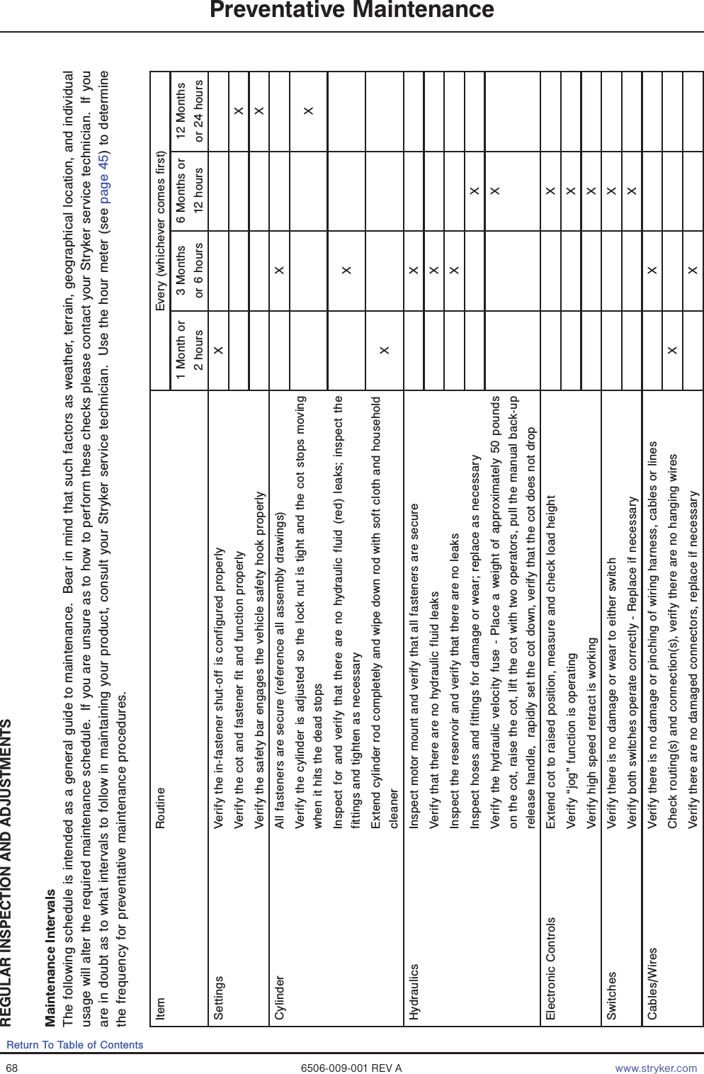
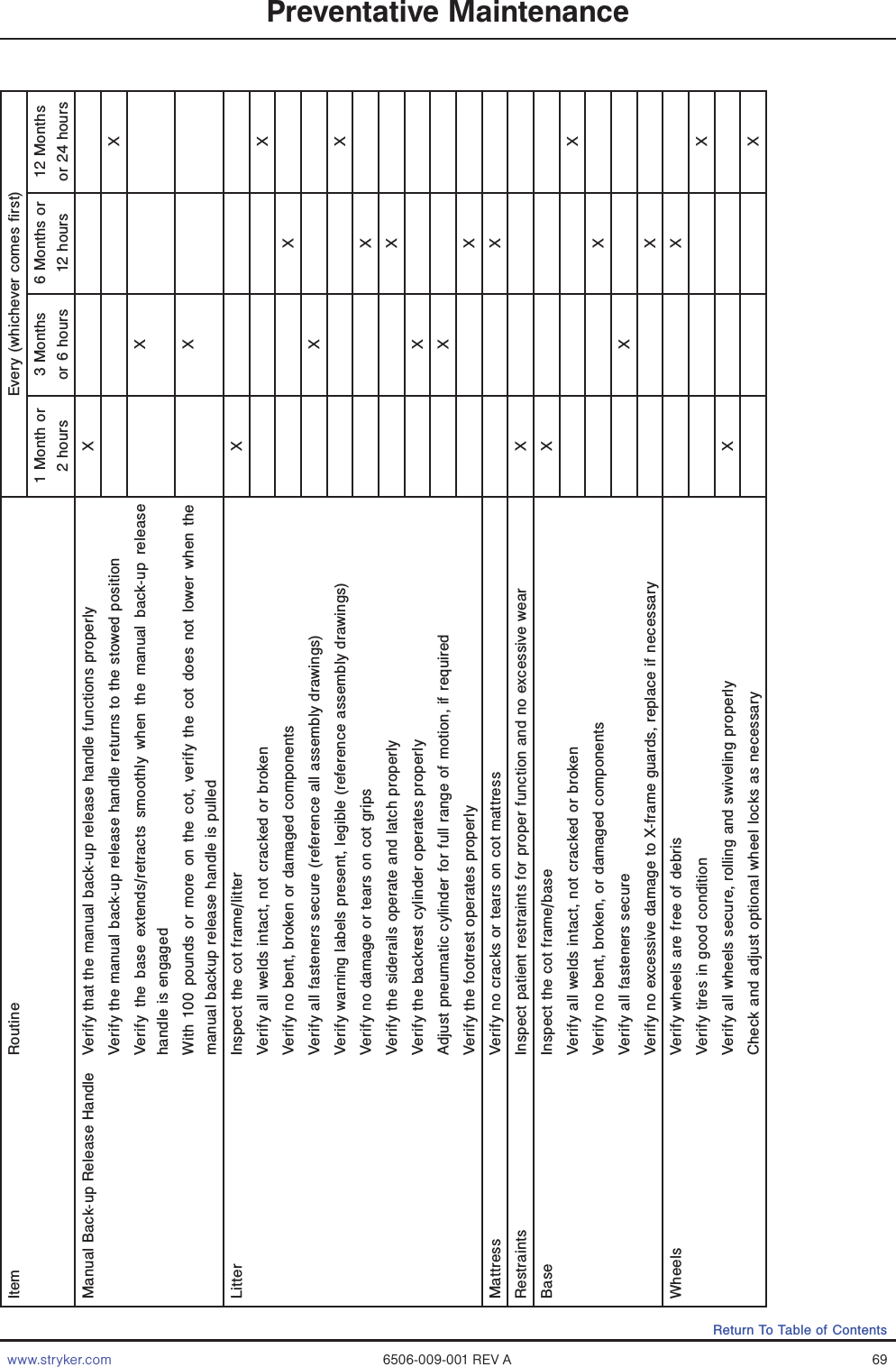
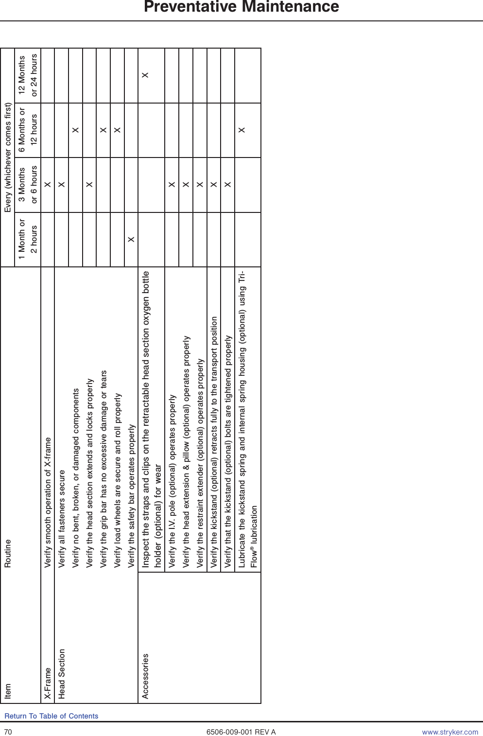
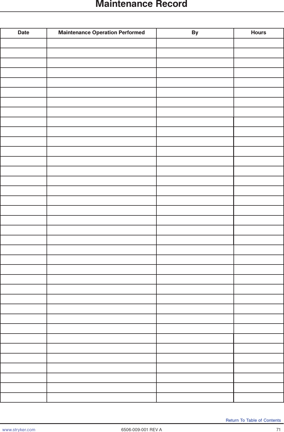
User Manual
Discussion / Help
Navigation