TON ELECTRONICS TECHNOLOGY TK310 GPS Vehicle Tracker User Manual
TOPTEN ELECTRONICS TECHNOLOGY LIMITED GPS Vehicle Tracker
UserManual.wiki
>
TON ELECTRONICS TECHNOLOGY
>
TK310 User Manual
User Manual
Navigation menu
Upload a User Manual
Namespaces
Wiki Guide
HTML
PDF
Info
Views
User Manual
Discussion / Help
Navigation
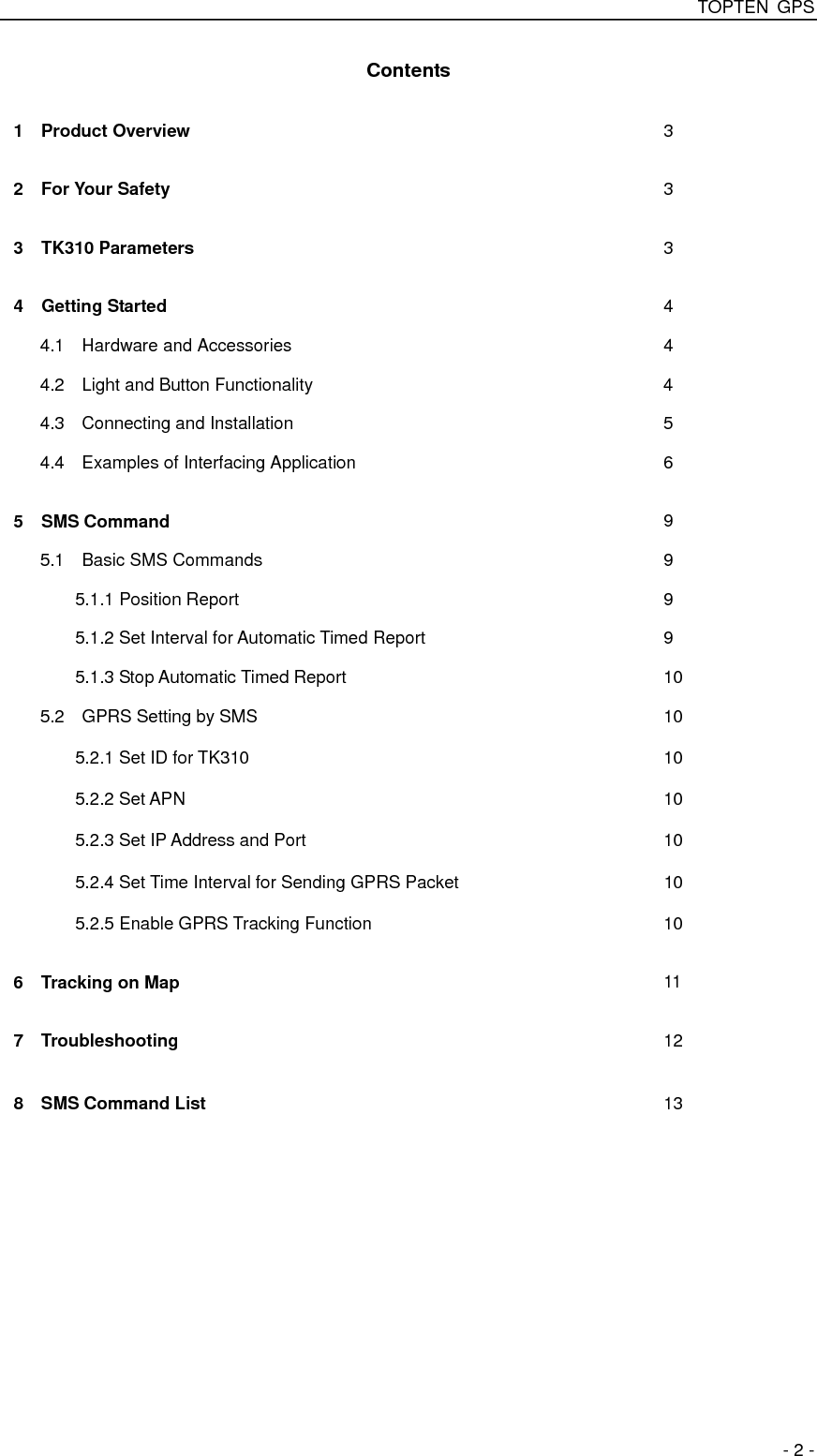

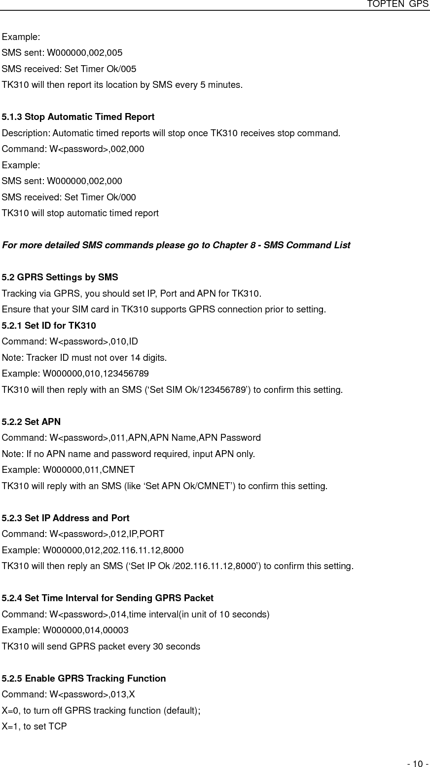

![TOPTEN GPS - 14 - Set over speed alert When TK310 speeds higher than the preset value, it will send an SMS to the SOS preset number. W******,005,XX XX (the preset value of speed) =00 , to turn off this function =[01, 20] (unit: 10Km/h) For example, W000000,005,08, it will sent alert when it is over 80Km/h Set Geo-fence alert When the TK310 moves out of preset scope, it will send one Geo-fence SMS to the SOS preset number. W******,006,XX XX ( preset distance to original place ) =00, close =01, 30m =02, 50m =03, 100m =04, 200m =05, 300m =06, 500m =07, 1000m =08, 2000m](https://usermanual.wiki/TON-ELECTRONICS-TECHNOLOGY/TK310/User-Guide-1236117-Page-14.png)
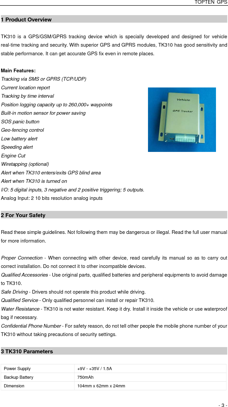
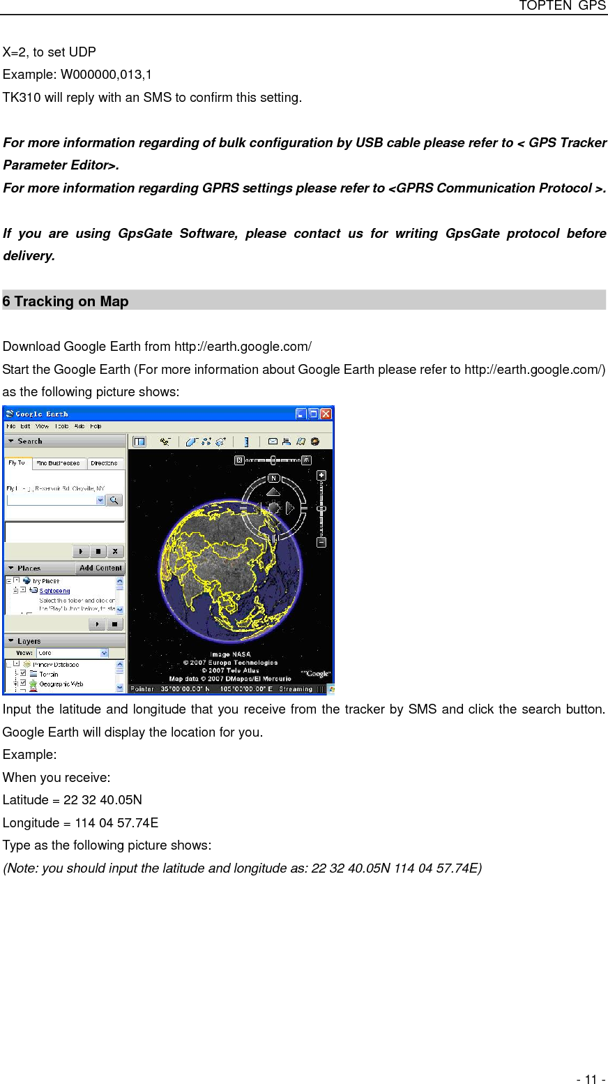
![TOPTEN GPS - 16 - Presetting by SMS for GPRS tracking (Ensure that your SIM card supports GPRS connection prior to setting) Set ID for TK310 W******,010,ID Tracker ID must not over 14 digits. Set APN W******,011,APN,APNName,APN Password If no APN name and password required, just insert APN only; APN defaulted as ‘CMNET’; APN + APN name + password not over 39 characters. Set IP Address and Port W******,012,IP, Port IP: xxx.xxx.xxx.xxx Port: [1,65534] Enable GPRS Tracking Function W******,013,X X=0, close GPRS (default); X=1, enable TCP X=2, enable UDP Set Time Interval for Sending GPRS Packet W******,014,XXXXX XXXXX should be in five digitals and in unit of 10 seconds. XXXXX=00000, to close this function; XXXXX=00001~65535, time interval for sending GPRS packet and in unit of 10 seconds. For more information regarding GPRS settings please refer to <GPRS Communication Protocol> Output Control W******,020,P,F P =1, Out1 =2, Out2 =3, Out3 =4, Out4 =5, Out5 F =0, to close the output =1, to open the output Output Control (Safe mode) This function is achievable when the speed is below 10km/h and GPS is available. W******,120,ABCDE ABCDE represents Out1, Out2, Out3, Out4, and Out5 respectively. If A or B or C or D or E, =0, to close the output =1, to open the output =2, to remain previous status Set sleep mode for saving power W******,021,XX### XX=00 turn off sleep mode XX=01 sleep mode XX=02 deep sleep mode ### is the ending character Set power saving mode when TK310 is inactive (In power saving mode, GPS stops working. GSM enters standby mode and stop sending out message until it is activated by an SMS or an incoming call) W******,026,XX XX=00, to turn off this function XX=01~99, to set this function. It is in unit of minute. Example: If XX=10, TK310 will enter power saving mode after it is immobile for 10 minutes.](https://usermanual.wiki/TON-ELECTRONICS-TECHNOLOGY/TK310/User-Guide-1236117-Page-16.png)
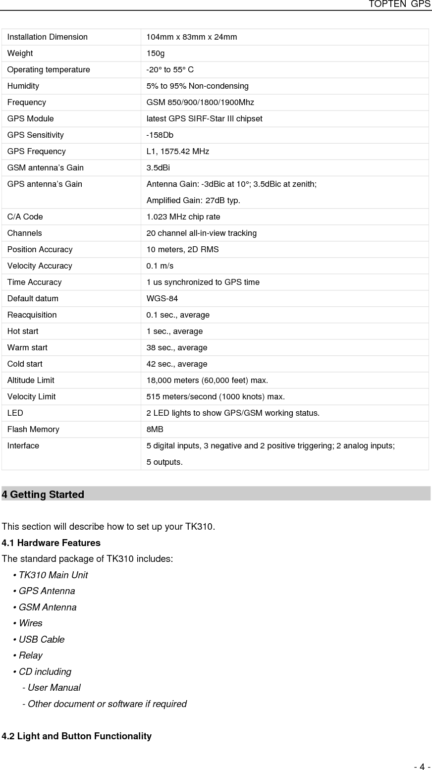
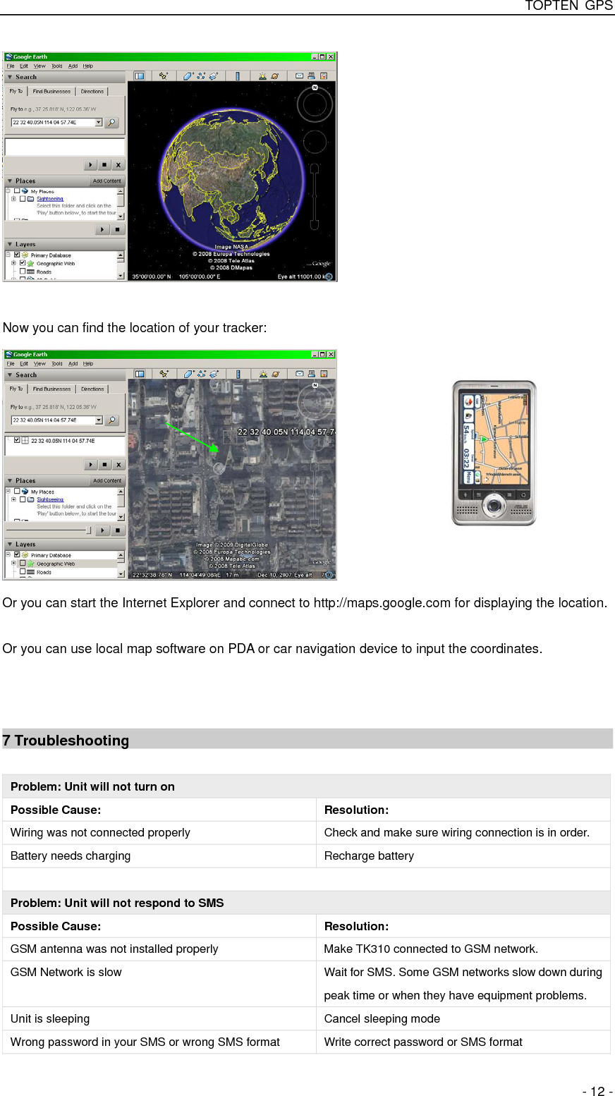
![TOPTEN GPS - 17 - Set phone number for wiretapping W******,030,T T is the telephone number for wiretapping and max. 16 digits Set interval for logging (Note: this interval is not relevant to the interval of continuous tracking) W******,031,X X=0, to turn off this function X=[1, 65535] to set interval in second. For example, W000000,031,60, TK310 will store location data every 60 seconds. Set time zone difference W******,032,T T=0, to turn off this function T=[1, 65535] to set time difference in minute to GMT. Default value is GMT For those ahead of GMT, just input the time difference in minute directly. For example, W000000,032,120 ‘-‘is required for those behind GMT. For example, W000000,032,-120. Set character for SOS alert message W******,033,1,Char Char is the character in SOS message and max 32 characters Get version and serial number W******,600 To get version and serial number of current firmware Get IMEI W******,601 To get IMEI This device complies with Part 15 of the FCC Rules. Operation is subject to the following two conditions: (1) this device may not cause harmful interference, and (2) this device must accept any interference received, including interference that may cause undesired operation. This equipment complies with FCC RF radiation exposure limits set forth for an uncontrolled environment. This device and its antenna must not be co-located or operating in conjunction with any other antenna or transmitter. “To comply with FCC RF exposure compliance requirements.The antennas used for this transmitter must be installed to provide a separation distance of at least 30 cm from all persons and must not be co-located or operating in conjunction with any other antenna or transmitter.” Changes or modifications not expressly approved by the party responsible for compliance could void the user's authority to operate the equipment FCC ID: X3U-TK310 Model No.: TK310 Manufacturer: Topten electronics Technology Limited](https://usermanual.wiki/TON-ELECTRONICS-TECHNOLOGY/TK310/User-Guide-1236117-Page-17.png)