Telensa 2N4D Telensa Telecell street light control unit User Manual
Telensa Ltd. Telensa Telecell street light control unit
UserManual.wiki
>
Telensa
>
2N4D User Manual
User manual
Navigation menu
Upload a User Manual
Namespaces
Wiki Guide
HTML
PDF
Info
Views
User Manual
Discussion / Help
Navigation
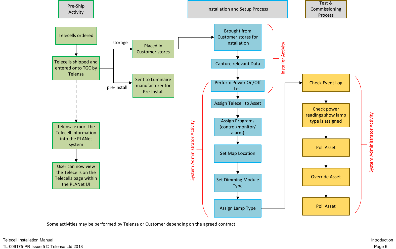
![Telecell Installation Manual Introduction TL-006175-PR Issue 5 © Telensa Ltd 2018 Page 1 Telecell Installation Manual CDox Original Author: Catherine Wijman Other Authors: [free text field] CDox Latest Issuer: Catherine Wijman Issue Date: 2018-02-08 Document Ref: TL-006175-PR Issue 5](https://usermanual.wiki/Telensa/2N4D/User-Guide-3864146-Page-1.png)
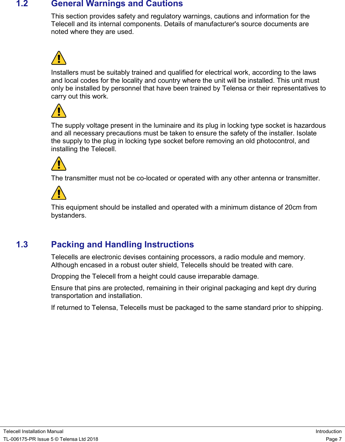
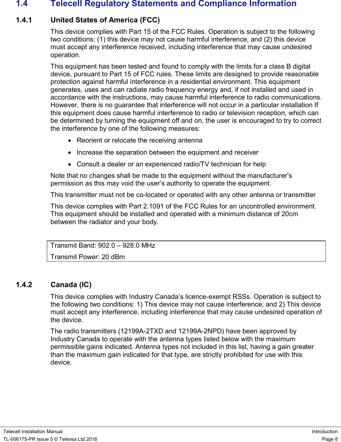
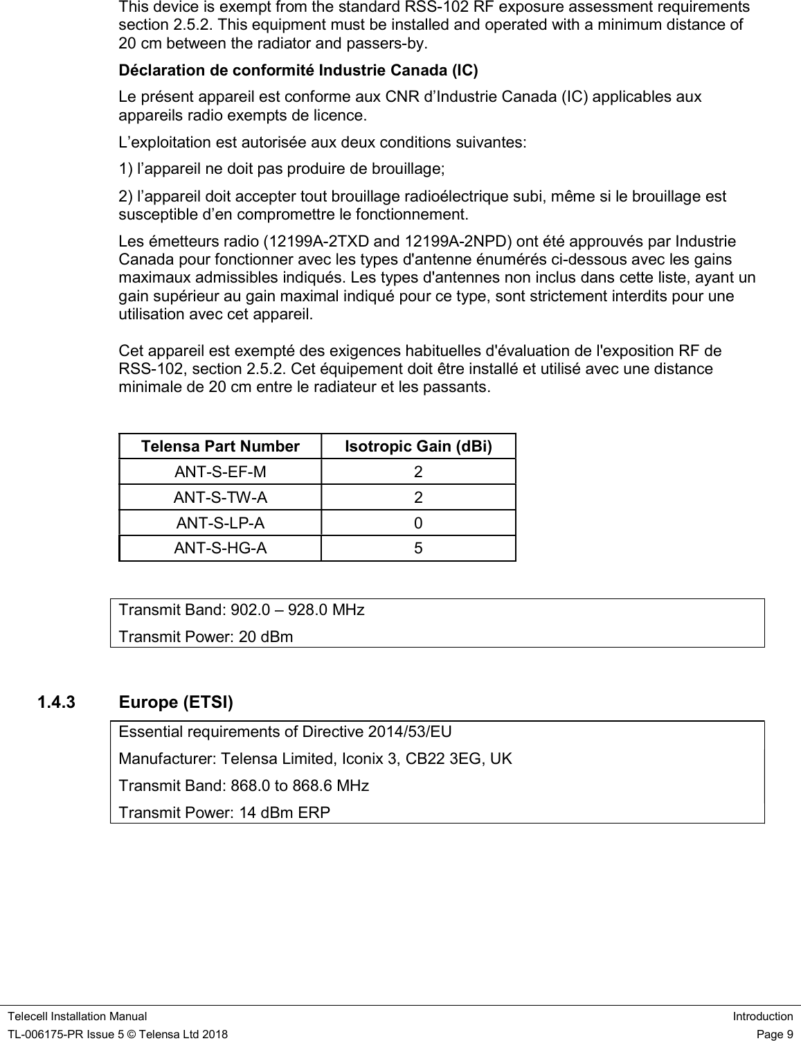
![Telecell Installation Manual Introduction TL-006175-PR Issue 5 © Telensa Ltd 2018 Page 10 1.5 Related Information [TL-000762-ST] System Glossary [TL-005536-PR] System Overview Manual [TL-005716-PR] PLANet User Guide 1.6 Terminology PLANet Public Lighting Active Network GPS Global Positioning System OOS Orphan Outstation OSID Outstation Identification Number OS Outstation ROS Relay Outstation 1.7 Essential information 1.7.1 Installer At the point of installation, it is important to match the Asset ID to the OSID. The installer must confirm the correct operation of the Power On / DIM / Off test cycle as follows: 1) Turn ON the mains supply to the Telecell. The lamp will illuminate for 50 seconds, then turn OFF. If the unit is fitted with a dimming unit it will illuminate for 50 seconds but after approximately 25 seconds it will DIM to approximately 50%. Note: When powered up, the unit may switch ON then momentarily switch OFF, this operation is normal and is the Telecell auto-sensing between Analogue and DALI. 2) After 50 seconds has elapsed the lamp will turn OFF.The test is now complete. There is an issue if the lamp fails to operate as described.](https://usermanual.wiki/Telensa/2N4D/User-Guide-3864146-Page-10.png)
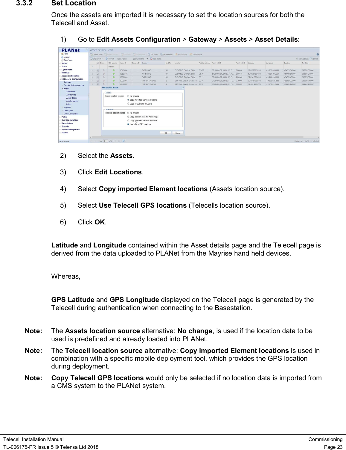

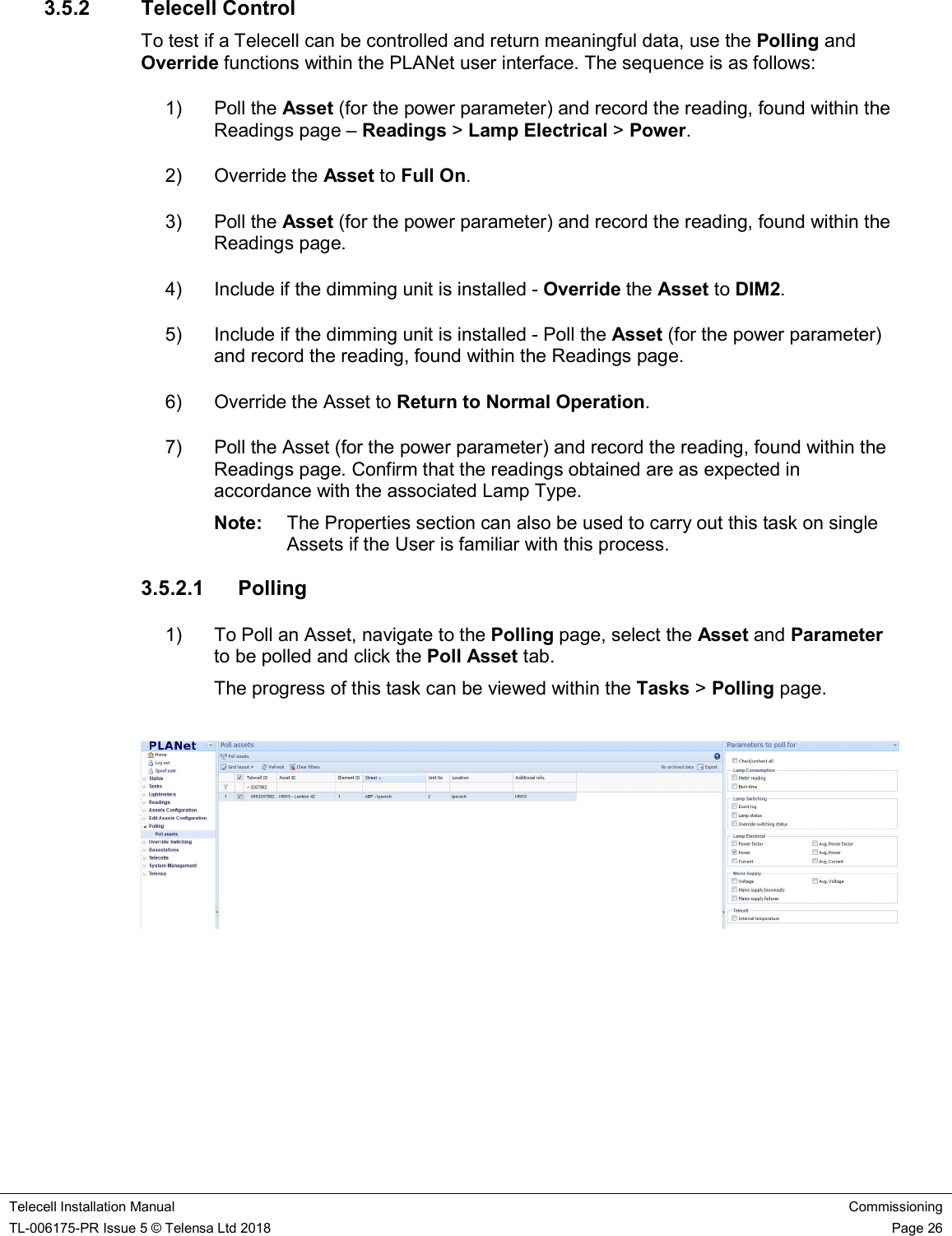
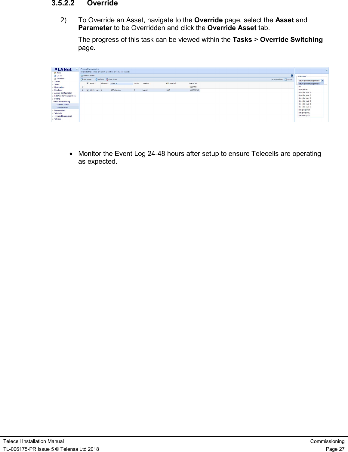
![Telecell Installation Manual Commissioning TL-006175-PR Issue 5 © Telensa Ltd 2018 Page 25 3.4 Operational Checks For a Telecell to be controlled and return meaningful data it must be set up correctly. Ensure each Telecell is: Connected Assigned to an Asset Has a Control Program with appropriate dimming levels set within the Power tab Has the correct Lamp Type and Charge Code Assigned (make a note of the Circuit Watts within the Charge Code) 3.5 Bring the Telecell into Service 3.5.1 Connection Status Once installed and powered, the Telecell should connect to the Central System within a few hours. This can be confirmed by observing the Telecells Page within the User Interface. Filter the Telecell ID column for the OSID. Note: When a Telecell connects, the Last Known Status column symbol turns green and data becomes present in the Last Connection Confirmation [data received] column. If the Telecell is not connected, the Test and Commissioning phase cannot be completed. Note: The Last Known Status column is the result of either the success or failure of any last communication with the Telecell.](https://usermanual.wiki/Telensa/2N4D/User-Guide-3864146-Page-25.png)
![Telecell Installation Manual Commissioning TL-006175-PR Issue 5 © Telensa Ltd 2018 Page 1 3.6 Example Installation Data Capture Sheet Asset ID Latitude Longitude Street Lamp Type Additional Information Confirm Power ON/DIM/OFF Test Attach Telecell Label 3.7 Example Commissioning Record Sheet Telecell ID (OSID) Asset ID Unit Number Lamp Type (Nominal Watt) Control Program Monitoring Program Alarm Program Power [ON/DIM/OFF] Test Cycle Override ON [Power] DIM1 [Power] DIM2 [Power] Pass/Fail](https://usermanual.wiki/Telensa/2N4D/User-Guide-3864146-Page-28.png)