Teles Informationstechnologien GSM32VOIPUS GSM Gateway User Manual TELES iGATE
Teles AG Informationstechnologien GSM Gateway TELES iGATE
UserManual.wiki
>
Teles Informationstechnologien
>
GSM32VOIPUS User Manual
User Manual
Navigation menu
Upload a User Manual
Namespaces
Wiki Guide
HTML
PDF
Info
Views
User Manual
Discussion / Help
Navigation

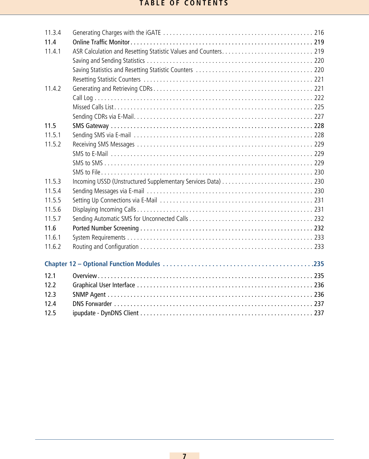
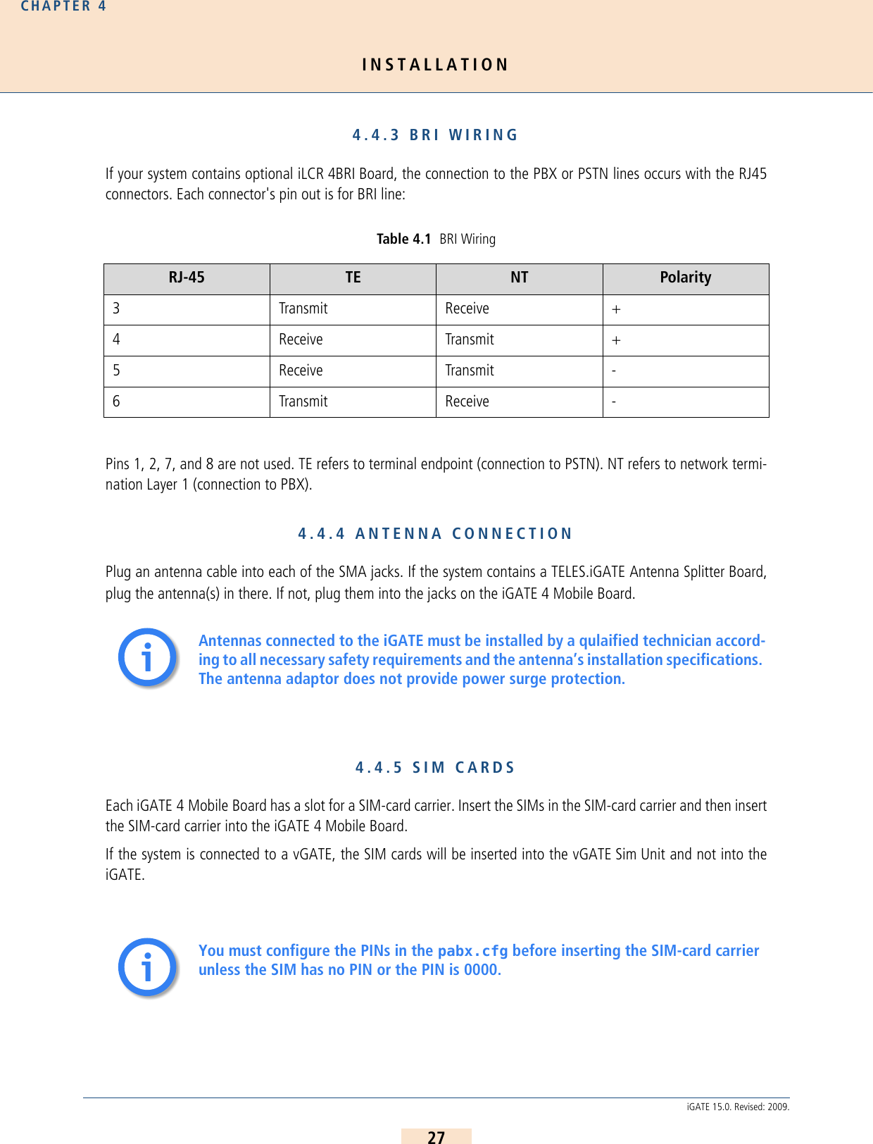
![TABLE OF CONTENTS45.3.1 Entries in the [System] Section . . . . . . . . . . . . . . . . . . . . . . . . . . . . . . . . . . . . . . . . . . . . . . . . . . . 82Mapping . . . . . . . . . . . . . . . . . . . . . . . . . . . . . . . . . . . . . . . . . . . . . . . . . . . . . . . . . . . . . . . . . . . 82Restrict. . . . . . . . . . . . . . . . . . . . . . . . . . . . . . . . . . . . . . . . . . . . . . . . . . . . . . . . . . . . . . . . . . . . . 83Redirect . . . . . . . . . . . . . . . . . . . . . . . . . . . . . . . . . . . . . . . . . . . . . . . . . . . . . . . . . . . . . . . . . . . . 84Setting the Time-Controlled Sections. . . . . . . . . . . . . . . . . . . . . . . . . . . . . . . . . . . . . . . . . . . . . . . 865.3.2 VoIP Profiles. . . . . . . . . . . . . . . . . . . . . . . . . . . . . . . . . . . . . . . . . . . . . . . . . . . . . . . . . . . . . . . . . 875.3.3 Gatekeeper Profiles . . . . . . . . . . . . . . . . . . . . . . . . . . . . . . . . . . . . . . . . . . . . . . . . . . . . . . . . . . . 915.3.4 Registrar Profiles . . . . . . . . . . . . . . . . . . . . . . . . . . . . . . . . . . . . . . . . . . . . . . . . . . . . . . . . . . . . . 925.3.5 Radius Profiles . . . . . . . . . . . . . . . . . . . . . . . . . . . . . . . . . . . . . . . . . . . . . . . . . . . . . . . . . . . . . . . 94Chapter 6 – Routing Examples. . . . . . . . . . . . . . . . . . . . . . . . . . . . . . . . . . . . . . . . . . . . . . . . . . . . .966.1 iGATE Integration in a Carrier Network. . . . . . . . . . . . . . . . . . . . . . . . . . . . . . . . . . . . . . . . . . . . 966.2 iGATE Integration with SIM-Card Switching in an H.323 Carrier Network . . . . . . . . . . . . . . . . . 976.3 iGATE as a Second-Generation LCR with VoIP . . . . . . . . . . . . . . . . . . . . . . . . . . . . . . . . . . . . . . 99Chapter 7 – Mobile Configuration Options . . . . . . . . . . . . . . . . . . . . . . . . . . . . . . . . . . . . . . . . . .1017.1 Connection to a vGATE . . . . . . . . . . . . . . . . . . . . . . . . . . . . . . . . . . . . . . . . . . . . . . . . . . . . . . . 1017.2 Module Distribution of Various Mobile Networks . . . . . . . . . . . . . . . . . . . . . . . . . . . . . . . . . . . 1017.3 Network-Specific Mobile Routing . . . . . . . . . . . . . . . . . . . . . . . . . . . . . . . . . . . . . . . . . . . . . . . 1037.3.1 Using a Fixed Mobile Port Address . . . . . . . . . . . . . . . . . . . . . . . . . . . . . . . . . . . . . . . . . . . . . . . 1037.3.2 Using the LAIN as the Mobile Port Address . . . . . . . . . . . . . . . . . . . . . . . . . . . . . . . . . . . . . . . . . 1047.3.3 Fixed LAIN for a Mobile Port . . . . . . . . . . . . . . . . . . . . . . . . . . . . . . . . . . . . . . . . . . . . . . . . . . . . 1057.4 Incoming Voice Calls from Mobile. . . . . . . . . . . . . . . . . . . . . . . . . . . . . . . . . . . . . . . . . . . . . . . 1057.5 Blocking Ports . . . . . . . . . . . . . . . . . . . . . . . . . . . . . . . . . . . . . . . . . . . . . . . . . . . . . . . . . . . . . . 1057.6 Setting Limits. . . . . . . . . . . . . . . . . . . . . . . . . . . . . . . . . . . . . . . . . . . . . . . . . . . . . . . . . . . . . . . 1067.7 Automatic SIM Switching . . . . . . . . . . . . . . . . . . . . . . . . . . . . . . . . . . . . . . . . . . . . . . . . . . . . . 1077.7.1 Switching SIMs. . . . . . . . . . . . . . . . . . . . . . . . . . . . . . . . . . . . . . . . . . . . . . . . . . . . . . . . . . . . . . 1087.7.2 Cyclical SIM Switching . . . . . . . . . . . . . . . . . . . . . . . . . . . . . . . . . . . . . . . . . . . . . . . . . . . . . . . . 1087.7.3 Immediate SIM Switching . . . . . . . . . . . . . . . . . . . . . . . . . . . . . . . . . . . . . . . . . . . . . . . . . . . . . . 1087.7.4 Count Status Information . . . . . . . . . . . . . . . . . . . . . . . . . . . . . . . . . . . . . . . . . . . . . . . . . . . . . . 1097.8 Defining Time Limits for Calls . . . . . . . . . . . . . . . . . . . . . . . . . . . . . . . . . . . . . . . . . . . . . . . . . . 1097.9 Pause between Two Calls . . . . . . . . . . . . . . . . . . . . . . . . . . . . . . . . . . . . . . . . . . . . . . . . . . . . . 1107.10 Time-Controlled SIM Switching . . . . . . . . . . . . . . . . . . . . . . . . . . . . . . . . . . . . . . . . . . . . . . . . . 1107.11 Mobile-User PBX Callback. . . . . . . . . . . . . . . . . . . . . . . . . . . . . . . . . . . . . . . . . . . . . . . . . . . . . 1127.12 Optional Mobile Quality Parameters . . . . . . . . . . . . . . . . . . . . . . . . . . . . . . . . . . . . . . . . . . . . . 1137.13 Deactivating Mobile ReRouting. . . . . . . . . . . . . . . . . . . . . . . . . . . . . . . . . . . . . . . . . . . . . . . . . 1167.14 Disconnecting Calls After Ring . . . . . . . . . . . . . . . . . . . . . . . . . . . . . . . . . . . . . . . . . . . . . . . . . 1177.15 Checking Ports/Mobile Channels. . . . . . . . . . . . . . . . . . . . . . . . . . . . . . . . . . . . . . . . . . . . . . . . 1177.16 Recharging Prepaid SIMs. . . . . . . . . . . . . . . . . . . . . . . . . . . . . . . . . . . . . . . . . . . . . . . . . . . . . . 117](https://usermanual.wiki/Teles-Informationstechnologien/GSM32VOIPUS/User-Guide-1224551-Page-4.png)
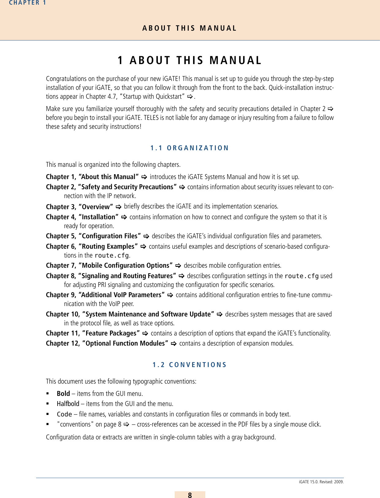
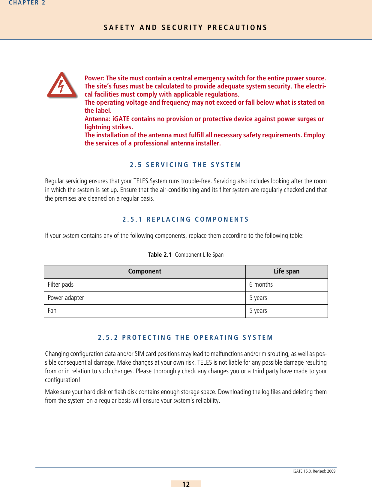
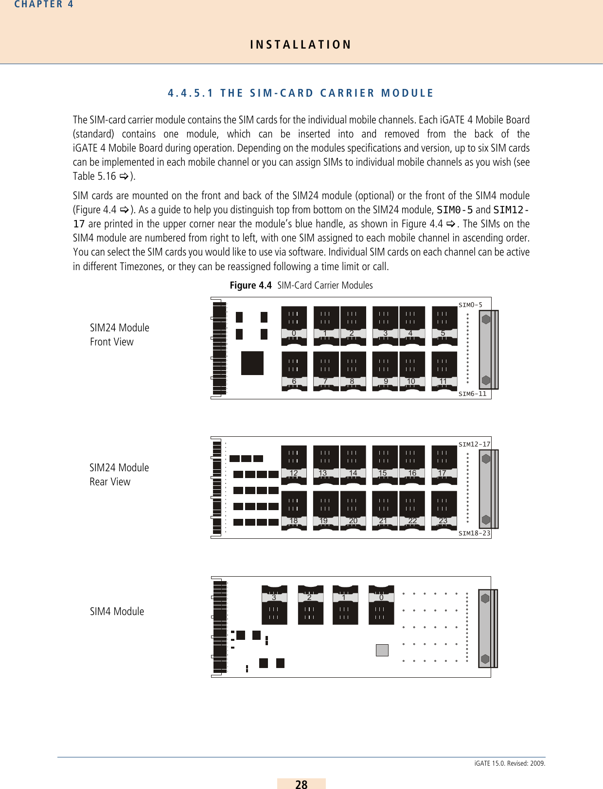
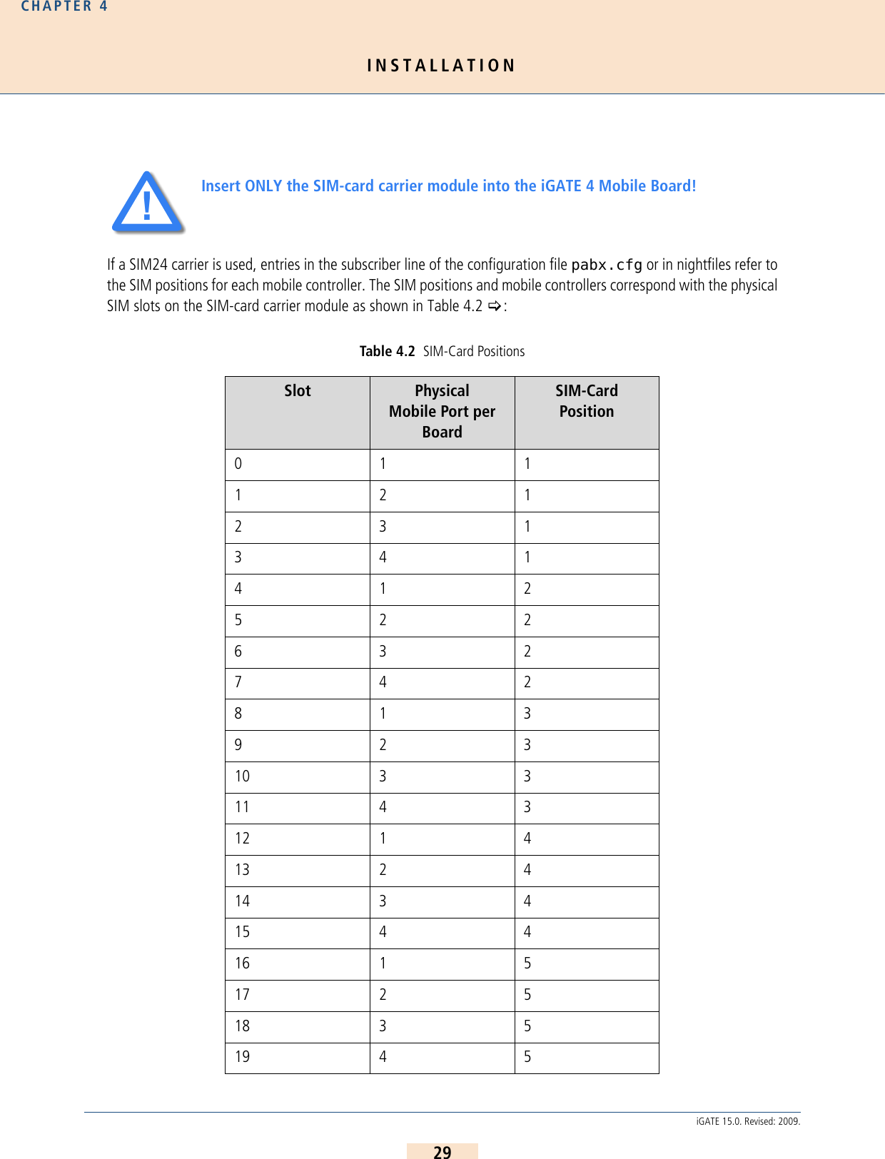
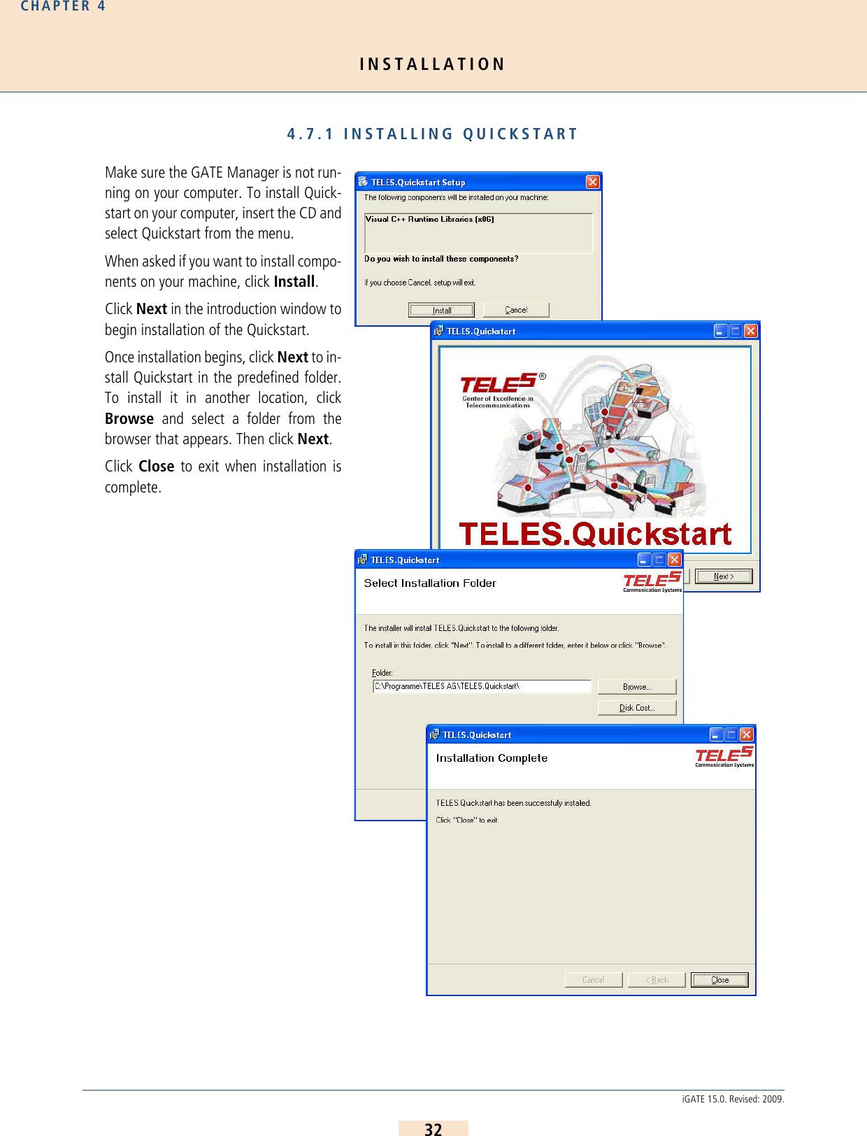
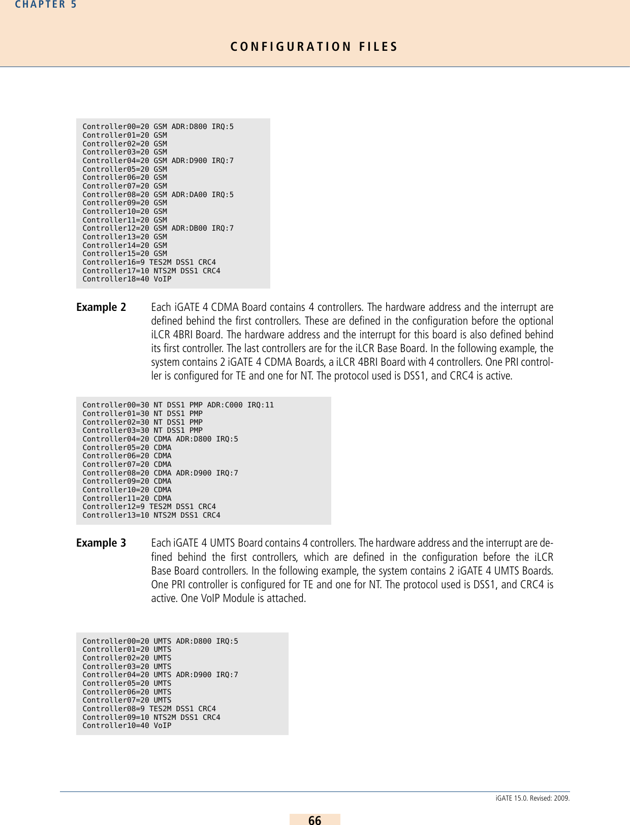
![INSTALLATIONCHAPTER 430iGATE 15.0. Revised: 2009.Example: In the following example, SIMs from various SIM positions in the SIM24 carrier are assigned toindividual GSM controllers. Bear in mind that the first GSM controller on the iGATE 4 GSM Boardhas the physical controller number 00 in the system. SIM 1, which corresponds with slot 0 on theSIM24 carrier, is assigned to the first GSM controller. 20 1 621 2 622 3 623 4 6Physical Controller Number in the SystemMobile Controller on the iGATE 4 Mobile BoardSIM Card Position for the Mobile ControllerSlot in the SIM24 Car-rier08 1 1 009 2 3 910 3 2 611 4 6 23Subscriber08 = TRANSPARENT ROUTER GSM[0000,00000,+00000,1,1,1,SIM24] CHADDR ALARM NEXTSubscriber09 = TRANSPARENT ROUTER GSM[0000,00000,+00000,3,1,1,SIM24] CHADDR ALARM Subscriber10 = TRANSPARENT ROUTER GSM[0000,00000,+00000,2,1,1,SIM24] CHADDR ALARMSubscriber11 = TRANSPARENT ROUTER GSM[0000,00000,+00000,6,1,1,SIM24] CHADDR ALARMTable 4.2 SIM-Card PositionsSlot Physical Mobile Port per BoardSIM-Card Position](https://usermanual.wiki/Teles-Informationstechnologien/GSM32VOIPUS/User-Guide-1224551-Page-30.png)
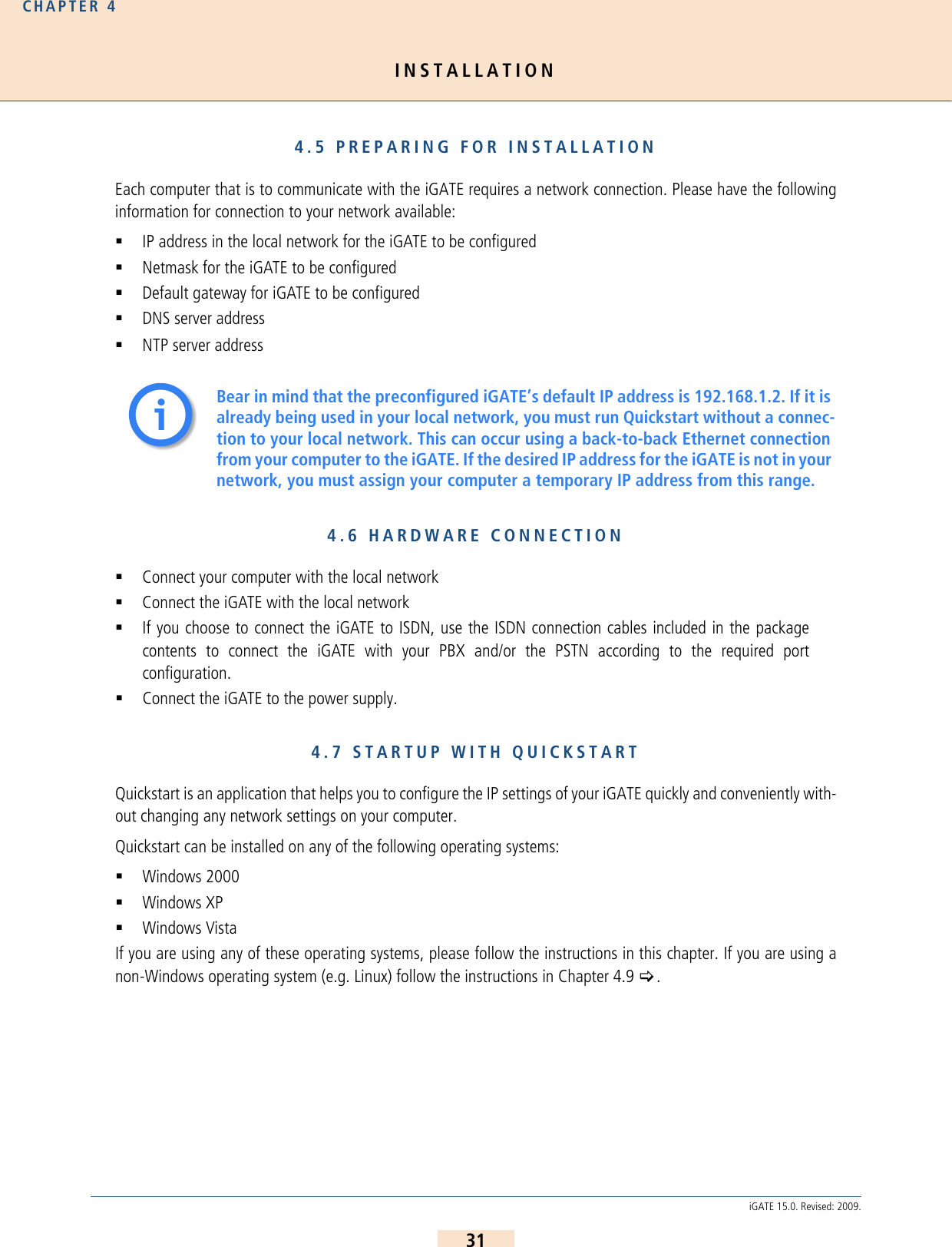
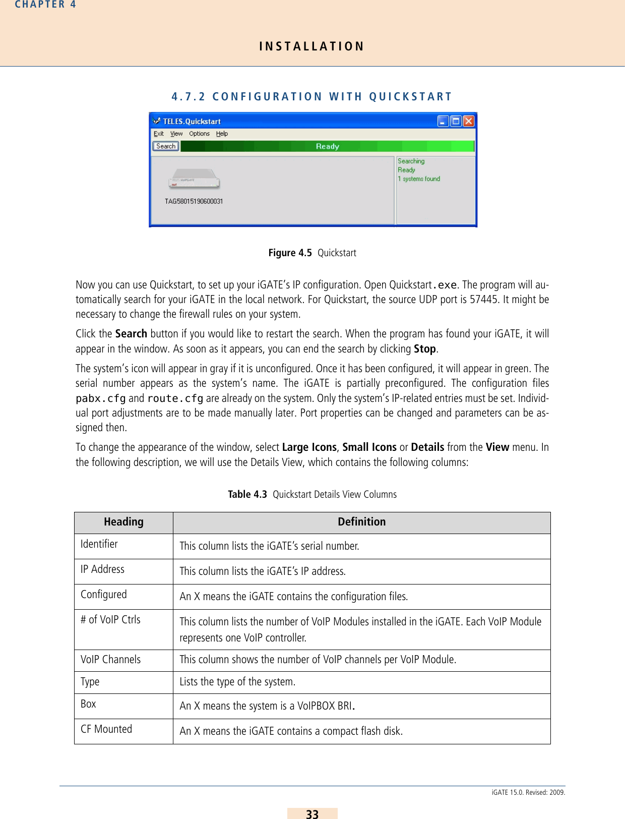
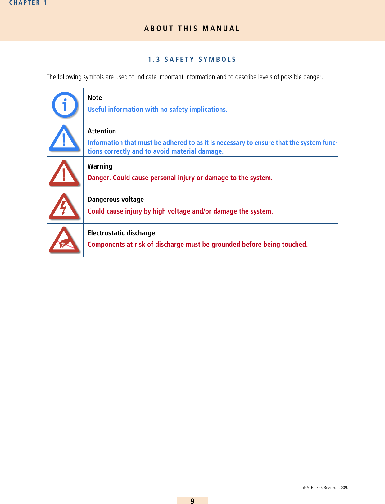
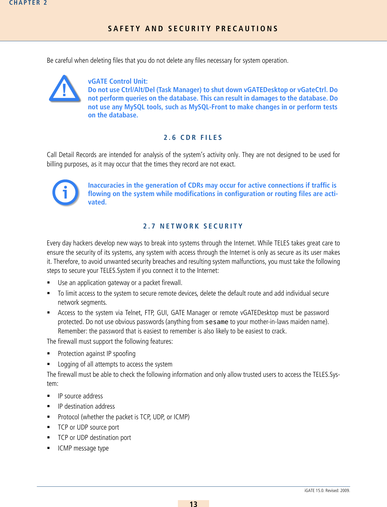
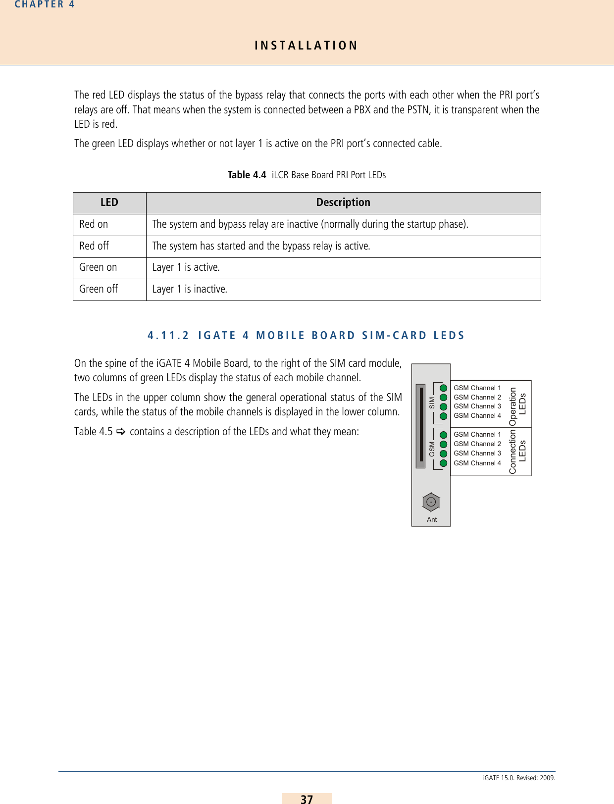
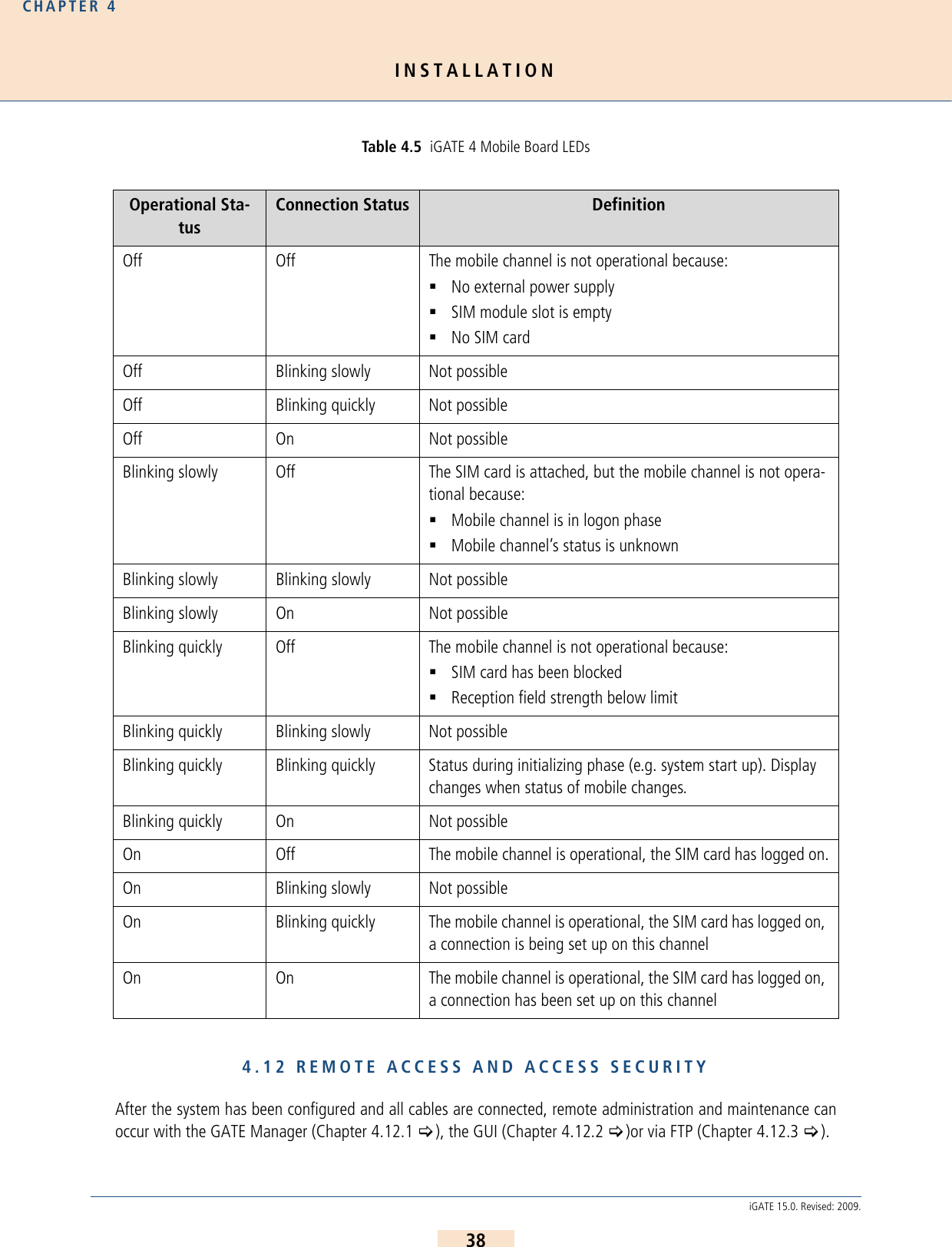
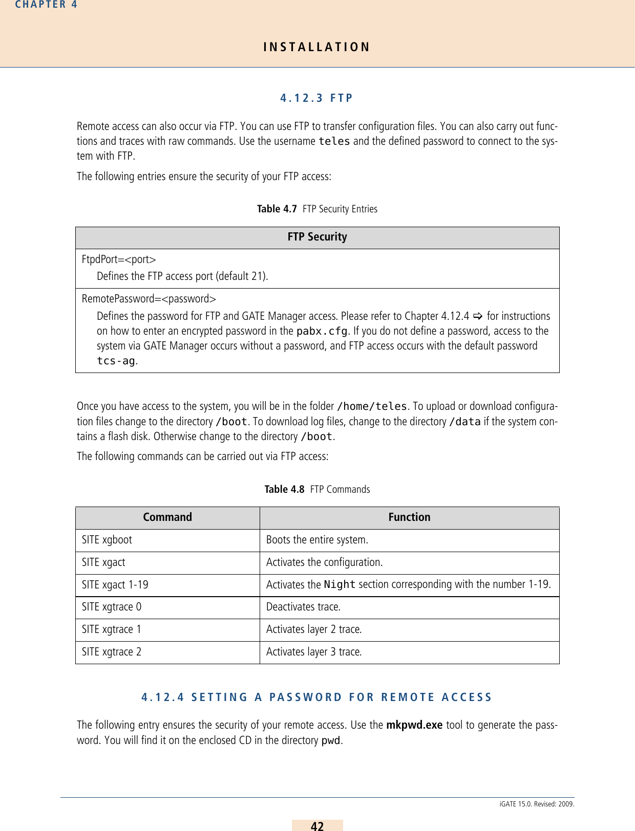
![INSTALLATIONCHAPTER 436iGATE 15.0. Revised: 2009.4.9 STARTUP VIA FTPIf you are using a computer that does not use a Windows operating system, you can preconfigure the iGATE viaFTP. The iGATE’s default IP address is 192.168.1.2. To configure the iGATE using FTP, you must assign your com-puter an IP address from network range 192.168.1.0 Class C and then access the iGATE via FTP.The default user is teles and the default password is tcs-ag. To configure the system, use the default configurationfile example on the CD in the Configfiles directory and the following four subdirectories:IPconfigThis subdirectory contains the file (ip.cfg) responsible for configuration of the Ethernet interface.carrierThis subdirectory contains a configuration (pabx.cfg, route.cfg) for iGATE 32 withiGATE 4 GSM Boards and VoIP.corporateThis subdirectory contains a configuration (pabx.cfg, route.cfg) for iGATE 16 withiGATE 4 GSM Boards.umts_systemThis subdirectory contains a configuration (pabx.cfg, route.cfg) for iGATE 16 withiGATE 4 UMTS Boards.bri_systemThis subdirectory contains a configuration (pabx.cfg, route.cfg) for iGATE 8 withiGATE 4 GSM Boards and an optional iLCR 4BRI Board.To edit the default configuration, follow the directions in Chapter 5 >. Upload the configuration files into the /boot directory.4.10 SELF PROVISIONING WITH NMSWith a management connection to the NMS (Network Management System), the iGATE can retrieve its configura-tion files from the configured NMS. That means that custom configuration of the device occurs automatically whenthe device is started. The following setting must be made in the [System] section of the pabx.cfg:AlarmCallback=<ip address NMS server>RemoteCallback=<ip address NMS server> <time> <days of week + holiday>As soon as the device is started, it connects automatically with the NMS, which uses the device’s TAG number tosend a prepared configuration. For further information on configuration of the NMS, please refer to the NMS Sys-tems Manual.4.11 LED FUNCTIONALITY4.11.1 ILCR BASE BOARD PRI PORT LEDSEach PRI port has one red and one green LED to show the port’s status.](https://usermanual.wiki/Teles-Informationstechnologien/GSM32VOIPUS/User-Guide-1224551-Page-36.png)
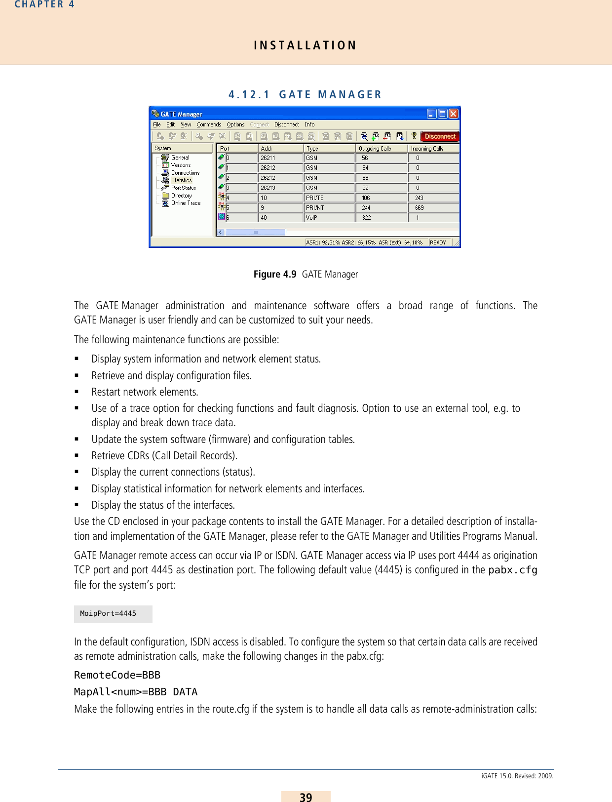
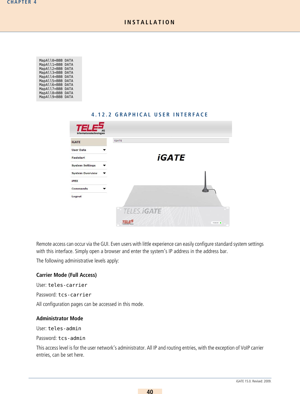
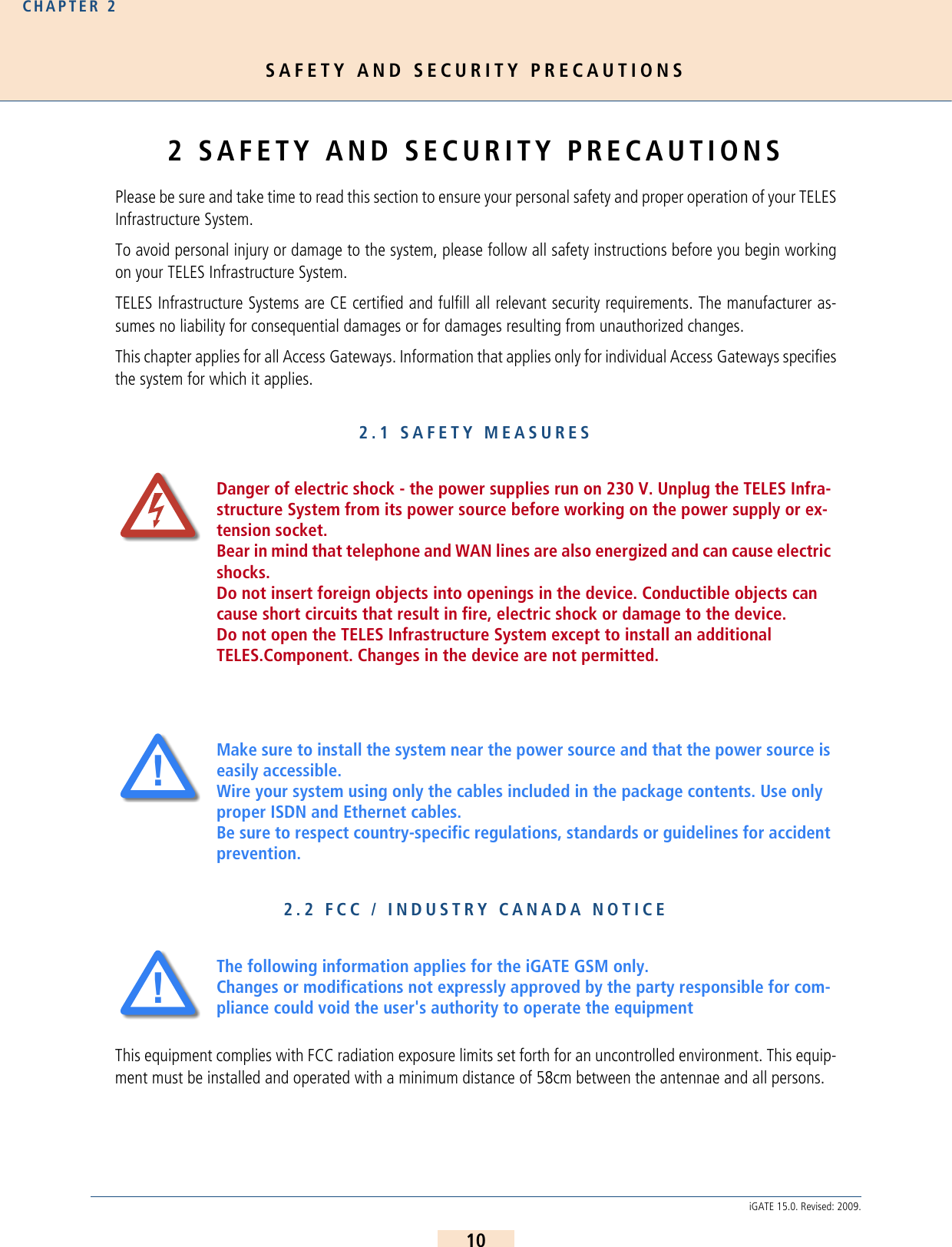
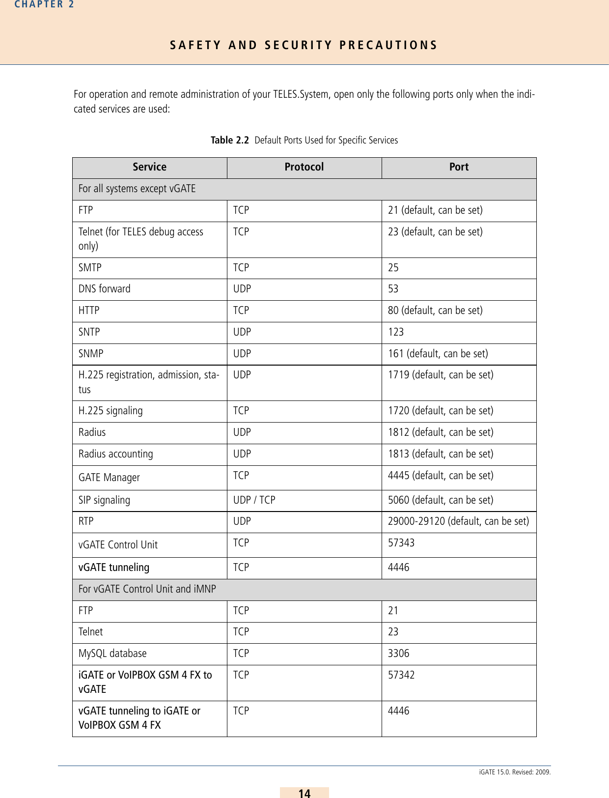
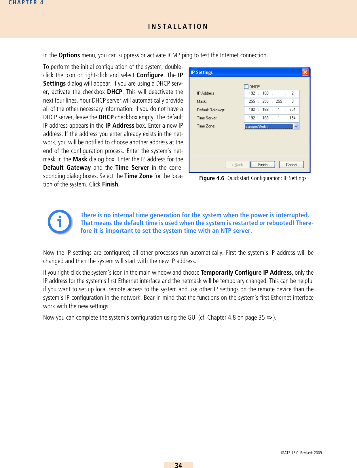
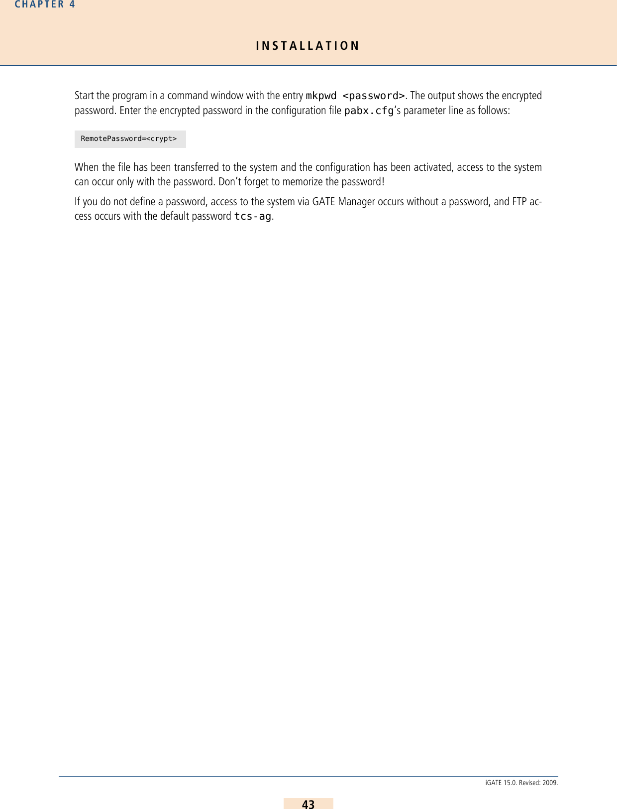
![INSTALLATIONCHAPTER 441iGATE 15.0. Revised: 2009.Read-Only ModeUser: teles-userPassword: tcs-userNo configuration changes can be made at this level. Only status and statistics can be retrieved.Of course, these configuration levels correspond with the most important scenarios. The passwords are saved inthe ip.cfg in encrypted form:PwdCarrier=<crypt>PwdAdmin=<crypt>PwdUser=<crypt>Example: The user interface is divided into the following main sections: All of the user interface’s pages contain Help buttons and links to the online help, which provides a detailed de-scription of all of the individual configuration settings.[httpd]PwdUser=k24X0sdc.uMcMPwdAdmin=k2UMj19qtovzIPwdCarrier=k2jryo6Xd5vN6Never copy these entries from one system to another, as the encryption is unique for each system.Table 4.6 GUI: Sections Section DescriptionUser Data Here you can change the user passwords and the language for the GUI.System Settings IP Settings: Settings for the Ethernet interfaces and related services.Port Settings: Settings for the VoIPBOX GSM/CDMA 4 FXs ports.VoIP Settings: VoIP settings for the SIP or H.323 carrier.Telephony Routing:Routings for telephone numbers.System Overview Overview of system information and drivers.Telephony Routing VoIP settings for the SIP or H.323 carrier and routings for telephone num-bers.Commands Here you can activate a configuration or restart the system.ii](https://usermanual.wiki/Teles-Informationstechnologien/GSM32VOIPUS/User-Guide-1224551-Page-41.png)
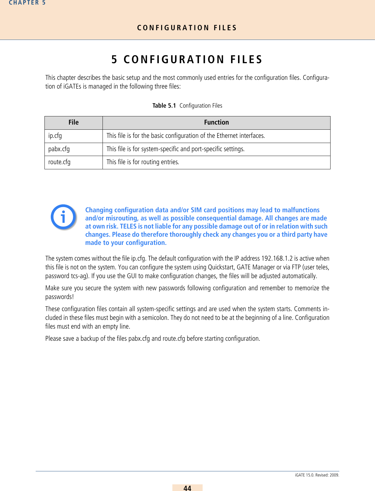
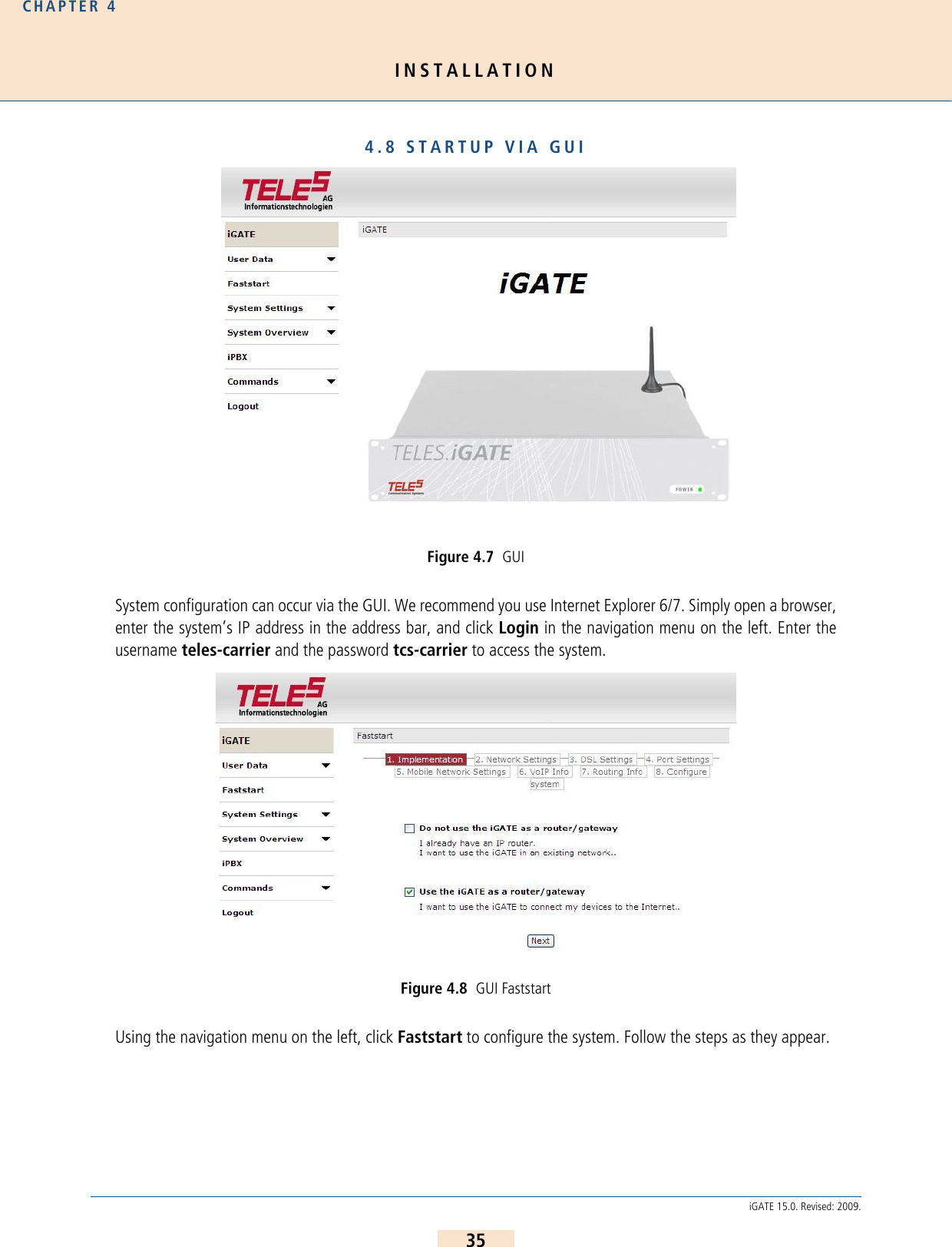
![CONFIGURATION FILESCHAPTER 545iGATE 15.0. Revised: 2009.The configuration files follow these conventions: Individual files are divided into sections. These sections alwaysbegin with a line entry in square brackets. The basic required sections are in these files: 5.1 CONFIGURATION FILE IP.CFGThe basic settings for the two Ethernet interfaces are entered here. One interface usually suffices. The second in-terface can be used for special requirements, e.g. as a hub port, DSL router or vLAN interface. Generally, thesesettings are entered once and then left unchanged. This file contains the following sections, which must appear in the order given: Table 5.2 Required Configuration File SectionsSection File Function[System] pabx.cfgroute.cfgip.cfgThis section contains the system’s basic settings. [Night<num>]EXAMPLE: [Night1][Night2]pabx.cfgroute.cfgThis section contains time dependent entries that only apply for limited times.[emac0] ip.cfg This section contains the IP configuration for the first Ethernet in-terface.Table 5.3 Sections in the ip.cfg FileSection Function[System] (required) This section contains entries that define the default gateway and/or special routing entries.[emac0] (required)[emac1] (optional)The Ethernet Media Access Controller section(s) define the physical Ethernet interface(s).[nat] (optional) This section includes settings for Network Address Translation.[bridge0] (optional) These section(s) contain settings for the second Ethernet controller in bridge mode.[pppoe<x>] (optional) These sections contain settings for direct connection between the system and the DSLAM when the PPPoE protocol is used. <x> can be 0 or 1.[firewall] (optional) This section contains settings for activating the system’s firewall.](https://usermanual.wiki/Teles-Informationstechnologien/GSM32VOIPUS/User-Guide-1224551-Page-45.png)
![CONFIGURATION FILESCHAPTER 546iGATE 15.0. Revised: 2009.5.1.1 SYSTEM SECTION CONFIGURATIONThe [System] section contains entries that define the default gateway and/or special routing entries. To define the standard gateway, use the following entry to set the IP address:DefaultGw=<ip addr>Example:If you must route specific net ranges to gateways other than what is defined in the default route, make the follow-ing entries in the [System] section:Route=<target range> -netmask <ip mask> <ip gateway>Example:If only certain routes apply, leave the line DefaultGw empty.5.1.2 ETHERNET INTERFACE CONFIGURATIONThe system includes two Ethernet interfaces (emac0 and emac1). Only the first is active in the default configuration.Therefore, make sure you plug the cable into the right controller. The second Ethernet interface can be configuredas needed.The following settings are possible for the sections [emac0] (matched to the first Ethernet controller) and [emac1](matched to the second Ethernet controller):IpAddress=<ip addr>/<netmask> The IP address is entered in decimal notation, followed by a slash (/) and the netmask in bit notation.[altqd] (optional) This section enables prioritization of VoIP packets in the iGATE through an IP network using bandwidth control.[dhcpd] (optional) This sections contains a list of parameters and settings for the DHCP server in the system. It is divided into global settings for the server and parameters for the DHCP subnet.[xppp<x>] (optional) This section contains settings for point-to-point dial-up setup via ISDN.[vlan<x>] (optional) These section(s) contain settings for the virtual networks. <x> can be any-thing from 0 to 9.[System]DefaultGw=192.168.1.254[System]DefaultGw=192.168.1.254Route=10.0.0.0 -netmask 255.0.0.0 192.168.1.1Table 5.3 Sections in the ip.cfg FileSection Function](https://usermanual.wiki/Teles-Informationstechnologien/GSM32VOIPUS/User-Guide-1224551-Page-46.png)
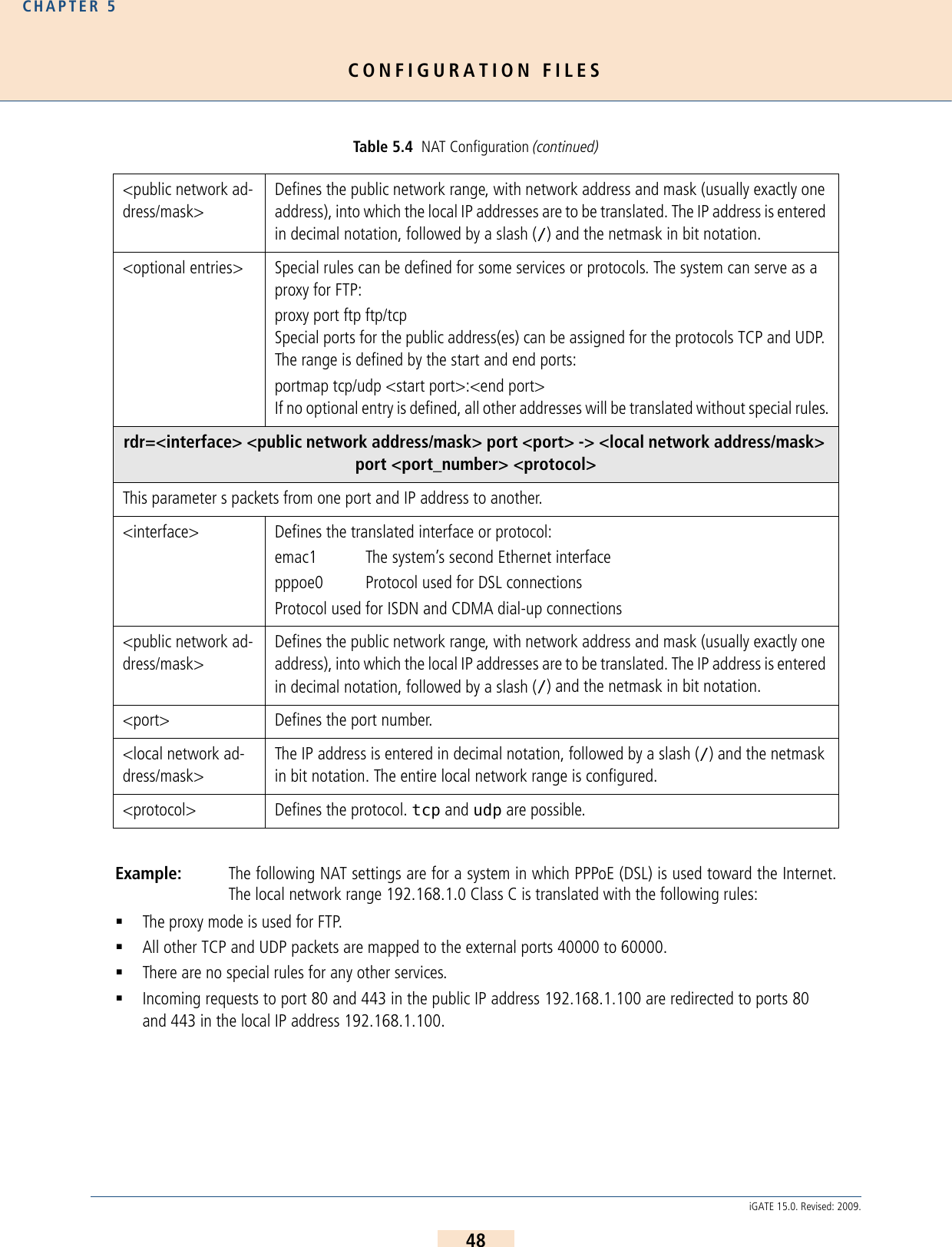
![CONFIGURATION FILESCHAPTER 547iGATE 15.0. Revised: 2009.Example:The following entry is used to allocate an IP address via DHCP: IpAddress=dhcpThe following entry is used in the [emac1] section if operation of the system is occurs in bridge mode.IpAddress=up5.1.3 BRIDGE CONFIGURATIONA bridge can connect two networks with each other. A bridge works like a hub, forwarding traffic from one inter-face to another. Multicast and broadcast packets are always forwarded to all interfaces that are part of the bridge.This can occur on the Ethernet or VLAN level:BrConfig=add <interface-x> add <interface-y> upActivating another Ethernet interface in this way is useful, for example, when the Ethernet switch does not haveany more ports available for connection of the system. You can simply unplug a cable and plug it into the system’ssecond Ethernet interface.Example:5.1.4 NAT CONFIGURATIONThe NAT (Network Address Translation) module translates IP addresses from the local network to an IP address orrange on a public interface. All rules are defined in the [nat] section: IpAddress=192.168.1.2/24[bridge0]BrConfig=add emac0 add emac1 upTable 5.4 NAT Configuration map=<interface> <local network address/mask> -> <public network address/mask> <optional entries>This parameter maps the IP address in the local network to the IP address in the public network.<interface> Defines the translated interface or protocol:emac1 The system’s second Ethernet interfacepppoe0 Protocol used for DSL connectionsxppp<0> Protocol used for ISDN and CDMA dial-up connections<local network ad-dress/mask>The IP address is entered in decimal notation, followed by a slash (/) and the netmask in bit notation. The entire local network range is configured.](https://usermanual.wiki/Teles-Informationstechnologien/GSM32VOIPUS/User-Guide-1224551-Page-47.png)
![CONFIGURATION FILESCHAPTER 549iGATE 15.0. Revised: 2009.5.1.5 PPPOE CONFIGURATIONThe protocol Point-to-Point over Ethernet is used for DSL communication with the DSLAM. That means the systemcan connect directly with the carrier network and terminate VoIP traffic directly. All necessary information for setup of the PPPoE connection is defined in the [pppoe<x>] section. That meansusername, password and authentication protocol are set here. The Ethernet interface is emac1 and the gatewaycan also be defined. The parameter PppoeIf defines the physical Ethernet interface used (always emac1). Thesettings are entered as follows:Bear in mind that configuration of the firewall, the NAT module and prioritizationof the VoIP packets must be considered when routing voice and data through the DSL line.Example: The following entry will create the interface pppoe0, with the username user and the pass-word pwd. The PAP authentication protocol is used. The default route occurs via DSL: 5.1.6 FIREWALL SETTINGSThe firewall settings provide options for limiting or denying access to and from the system. If you do not configurethis section, the firewall is inactive and access is unlimited.Example: In the following example, only port 4445 allows incoming connections from the IP address192.168.1.10. All others will be blocked.[nat]map=emac1 192.168.1.0/24 -> 0/32 proxy port ftp ftp/tcpmap=emac1 192.168.1.0/24 -> 0/32 portmap tcp/udp 40000:60000map=emac1 192.168.1.0/24 -> 0/32rdr=emac1 0/0 port 80 -> 192.168.1.100 port 80 tcprdr=emac1 0/0 port 443 -> 192.168.1.100 port 443 tcp[pppoe0]PppoeIf=emac1 User=userPwd=pwdAuthProto=papRoute=0.0.0.0Make sure you configure the firewall rules carefully. The rules are processed from top to bottom. If you use the option quick, you will break the sequence. We recomend that you put the most restrictive rule at the end of the configuration.[firewall]fw=pass in quick on emac0 proto tcp from 192.168.1.10/32 to any porteq 4445 flags S keepstate keep frags fw=block in log quick on emac0 all!!](https://usermanual.wiki/Teles-Informationstechnologien/GSM32VOIPUS/User-Guide-1224551-Page-49.png)
![CONFIGURATION FILESCHAPTER 550iGATE 15.0. Revised: 2009.Table 5.5 Settings in the [firewall] Section of the ip.cfg [firewall]fw=<mode> <direction> <list><mode> Two modes are possible for permitting or denying access:pass permits accessblock denies access<direction> Possible directions are in and out:in external to internalout internal to external<list> All other entries specify the other settings for the corresponding firewall rules and are optional. The order in the line is as listed below:log Records non-matching packets.quickAllows short-cut rules in order to speed up the filter or override later rules. If a packet matches a filter rule that is marked as quick, this rule will be the last rule checked, allowing a short-circuit path to avoid processing later rules for this packet. If this option is missing, the rule is taken to be a "fall-through rule, meaning that the result of the match (block/pass) is saved and that processing will continue to see if there are any more matches.on <interface>The firewall rule is used only for the defined interface (e.g. emac0, pppoe0).from <networkaddress/mask>to <networkaddress/mask>from defines the source IP-address range for incoming packets. to defines the target IP-address range for out-going packets. The IP address appears in decimal notation, followed by a slash (/) and the netmask in bit notation. any stands for all IP addresses (e.g.: to any).NOTE: If you use the rule pass in/out in combination with the option from <ip> to <ip>, you must specify a protocol number with proto and a port number. If you not specify the port, the system may not be reachable. EXAMPLE:fw=pass in quick on pppoe0 proto tcp from any to any port eq 4445proto <protocol>defines the protocol, for which the rule is valid (e.g.: proto tcp, proto udp, proto icmp).](https://usermanual.wiki/Teles-Informationstechnologien/GSM32VOIPUS/User-Guide-1224551-Page-50.png)
![CONFIGURATION FILESCHAPTER 551iGATE 15.0. Revised: 2009.Example:5.1.7 BANDWIDTH CONTROLIn many implementation scenarios, the iGATE in router mode (e.g. as DSL router) sends voice and data trafficthrough a connection with limited bandwidth. This can lead to lost voice packets that arrive too late to be used inthe voice stream. To avoid lost packets, this QOS setting prioritizes packet transmission. You must set the priorityfor voice signaling and for the voice packets. That means you must prioritize SIP/H.323, RTP and RTCP. You willfind the ports used in Table 5.13 >, in the following entries:H225PortSipPortVoipRtp Portport eq <num><num> defines the port as number (e.g.: port eq 4445).keep stateEnsures that the firewall checks packets from the beginning to the end of a session. This is necessary, as the firewall does not know when a session begins or ends.flags SOnly syn. packets are accepted and recorded in the state table. In conjunction with keep state, packets from sessions that have been inactive will also be routed. The advantage of this entry is that random packets will not be accepted.keep fragsFragmented packets are also routed.[firewall]; loopbackfw=pass in quick on emac0 allfw=pass out quick on emac0 all; traffic to outgoingfw=pass out quick on pppoe0 proto tcp all flags S keep state keep fragsfw=pass out quick on pppoe0 proto udp all keep state keep fragsfw=pass out quick on pppoe0 proto icmp all keep state keep frags; incoming trafficfw=pass in quick on pppoe0 proto tcp from 10.4.0.0/16 to any port eq 21 flags S keep state keep fragsfw=pass in quick on pppoe0 proto tcp from 10.4.0.0/16 to any port eq 23 flags S keep state keep fragsfw=pass in quick on pppoe0 proto tcp from 10.4.0.0/16 to any port eq 4445 keep state ; icmp trafficfw=pass in quick on pppoe0 proto icmp all keep state; other will be blockedfw=block in log quick on pppoe0 allfw=block out log quick on pppoe0 allTable 5.5 Settings in the [firewall] Section of the ip.cfg (continued)[firewall]fw=<mode> <direction> <list>](https://usermanual.wiki/Teles-Informationstechnologien/GSM32VOIPUS/User-Guide-1224551-Page-51.png)
![CONFIGURATION FILESCHAPTER 552iGATE 15.0. Revised: 2009.VoipRtpPortSpacingDifferent ports can be used for RTP and RTCP, depending on the configuration.The parameter VoipRtpPort shows the first RTP port used. The corresponding RTCP port is the next one up. Theparameter VoipRtpPortSpacing shows the next RTP port (RTP port + port spacing).Example: In the following example, prioritization is set for a thirty-channel VoIP connection. The SIP signal-ing port 5060 and the RTP/RTCP ports 29000 to 29059 are prioritized at level 7. All other servicesTable 5.6 Settings in the [altqd] Section of the ip.cfg interface <interface> bandwidth <bw> priqDefines the interface for which the rule applies.<interface> Sets the interface for which prioritization applies (e.e. pppoe0).<bw> Sets the bandwidth that is available on the interface in Kbit/s (e.g. 256K).priq Priority qeueing. A higher priority class is always served first.class priq <interface> <class> root priority <prio>Defines the priority of the filter entries.<class> Two types can be set:realtime_class (VoIP packets)regular_class (data packets)<prio> Enter a value between 0 and 15. The higher the value (e.g. 15), the higher the priority.filter <interface> <class> <values>Defines the individual rules for the class.<values> The individual values are divided into the following entries. A 0 can be entered as a wild-card, in which case all values are possible:<dest_addr> (can be followed by netmask <mask>)<dest_port><src_addr> (can be followed by netmask <mask>)<src_port><protocol tos value>:6 for TCP17 for UDP](https://usermanual.wiki/Teles-Informationstechnologien/GSM32VOIPUS/User-Guide-1224551-Page-52.png)
![CONFIGURATION FILESCHAPTER 553iGATE 15.0. Revised: 2009.are set at level 0:5.1.8 DHCP SERVER SETTINGSThe DHCP (Dynamic Host Configuration Protocol) server provides a mechanism for allocation of IP addresses toclient hosts. The section [dhcpd] contains a list of parameters and settings for the DHCP server in the system. Itis divided into global settings for the server and parameters for the DHCP subnet.[altqd]interface pppoe0 bandwidth 512K priqclass priq pppoe0 realtime_class root priority 7 filter pppoe0 realtime_class 0 5060 0 0 0 filter pppoe0 realtime_class 0 0 0 5060 0 filter pppoe0 realtime_class 0 29000 0 0 17 filter pppoe0 realtime_class 0 0 0 29000 17 filter pppoe0 realtime_class 0 29001 0 0 17 filter pppoe0 realtime_class 0 0 0 29001 17 .... filter pppoe0 realtime_class 0 29058 0 0 17 filter pppoe0 realtime_class 0 0 0 29058 17 filter pppoe0 realtime_class 0 29059 0 0 17 filter pppoe0 realtime_class 0 0 0 29059 17 class priq pppoe0 regular_class root priority 0 defaultTable 5.7 Settings in the [dhcpd] Section of the ip.cfg ; Global dhcp parametersallow unknown-clients;All DHCP queries are accepted and the configured settings are transmitted to the clients.ddns-update-style none;Deactivates dynamic update of the domain name system as per RFC 2136.; Parameters for the Subnetsubnet <network address> netmask <mask for network range> {<list>}In <list> you can enter any of the following specific network settings activated by the DHCP server. Each oprion must begin in a new line and end with a semicolon (;).range <start IP address> <end IP address>;The DHCP network range is defined by the first and last address in the range. Client assignment begins with the last address.option broadcast-address <IP address>;Defines the broadcast address for the clients in the subnet..option domain-name "<string>";Defines the domain name used in the network.](https://usermanual.wiki/Teles-Informationstechnologien/GSM32VOIPUS/User-Guide-1224551-Page-53.png)
![CONFIGURATION FILESCHAPTER 554iGATE 15.0. Revised: 2009.Example:5.1.9 PPP CONFIGURATION FOR ISDN AND CDMA DIAL-UPThe point-to-point protocol is used for dial-up connection via ISDN lines or via a mobile CDMA connection. Thatmeans the system can set up an Internet connection, which can be used for all local users or to transmit VoIP callsvia ISDN dial-up. Make sure you configure the firewall and NAT options accordingly.option domain-name-servers <IP address>;Defines the DNS-server address to be assigned (as per RFC 1035)All of the following optional entries defining server addresses are also transmitted as per RFC 1035. Separate multiple addresses per server with a comma: … <IP address>, <IP address>; (this also applies for all other optional entries with IP addresses).option netbios-name-servers <IP address>Defines the WINS-server address to be assigned.option ntp-servers <ip address>;Defines the NTP-server address to be assigned.option time-servers <ip address>;Defines the time-server address to be assigned (RFC 868).option routers <IP address>;Defines the router address to be assigned.option subnet-mask <net mask>;Defines the netmask to be assigned (as per RFC 950).option tftp-server-name "<link>";Defines the TFTP server name (option 66), as per RFC 2132.EXAMPLE: option tftp-server-name "http://192.168.0.9";[dhcpd]; Global dhcp parametersallow unknown-clients;ddns-update-style none;; Parameter for the Subnetsubnet 192.168.1.0 netmask 255.255.255.0 { range 192.168.1.3 192.168.1.20; option broadcast-address 192.168.1.255; option domain-name "company.de"; option domain-name-servers 192.168.1.100; option routers 192.168.1.2; option subnet-mask 255.255.255.0;}Table 5.7 Settings in the [dhcpd] Section of the ip.cfg (continued); Global dhcp parameters](https://usermanual.wiki/Teles-Informationstechnologien/GSM32VOIPUS/User-Guide-1224551-Page-54.png)
![CONFIGURATION FILESCHAPTER 555iGATE 15.0. Revised: 2009.The advantages of VoIP over ISDN can be seen especially in corporate implementation. For example, it is usefulwhen a very high number of connections occurs between subsidiaries and one subsidiary does not have a broad-band Internet connection. An ISDN B-channel can be connected to the Internet and up to six voice calls can occursimultaniously over one ISDN line. All necessary information for setup of the PPP connection is defined in the sec-tion [xppp<num>].The settings are entered as follows:Table 5.8 Settings in the [xppp] Section of the ip.cfg [xppp<num>]Dad=<num>Enter the dial-up number. Only digits can be defined here. Any required special characters (* or #) can be set in the mapping entry.User=<username>Enter a username.Pwd=<password>Enter a password.Route=<ip-addr>Enter the target IP address range, e.g. 0.0.0.0 (default route).AuthProto=<protocol>Enter chap or pap for the protocol used for authentication.AutoUp=<int>Defines if the PPP interface is activated automatically after system start. The following values are possible:0 = No automatic PPP activation (default)1 = Automatic PPP activationIdleTO=<sec>Enter the number of seconds without traffic before the interface tears down the connection.MTU=<int>Maximum Transfer Unit. We recommend the following default values:1500 for ISDN dial-up and 120 for CDMA dial-up.Rfc1662=<val>Framing to be used:0 for ISDN or 1 for CDMALcpTO=<msec>Allows you to change the value of the LCP timeout. The timeout-value must be specified in milliseconds (de-fault 1000).](https://usermanual.wiki/Teles-Informationstechnologien/GSM32VOIPUS/User-Guide-1224551-Page-55.png)
![CONFIGURATION FILESCHAPTER 556iGATE 15.0. Revised: 2009.Example:5.1.10 VLAN CONFIGURATIONA VLAN (Virtual Local Area Network) is a virtual LAN within a physical network. Each VLAN is assigned a uniquenumber (VLAN ID) and defined in the [vlan<x>] section with Tag: value between 1 and 4095Priority: value between 0 and 7 (0 is lowest and 7 is the highest priority)[vlan0]IfConfig=vlan <tag>,<priority> vlanif <interface>Example: The following entry will create the interface vlan1, with VLAN tag 10 and priority 7, on the Ether-net interface emac0. Following this configuration, IP addresses (and/or other protocols) can beassigned to the vlan1 interface: 5.1.11 EXAMPLES5.1.11.1 DEFAULT CONFIGURATIONIn the following example, the system’s IP address is 192.168.1.1, the netmask is 255.255.255.0, and the standardgateway is 192.168.1.254: StartDelay=<sec>Time in seconds the system will wait to start the ppp process.[xppp0]Dad=12345User=userPwd=pwdRoute=0.0.0.0AuthProto=chapIdleTO=60MTU=1500Rfc1662=0LcpTO=500StartDelay=10[vlan1]IfConfig=vlan 10,7 vlanif emac0IpAddress=192.168.199.1[System]DefaultGw=192.168.1.254[emac0]IpAddress=192.168.1.1/24Table 5.8 Settings in the [xppp] Section of the ip.cfg (continued)[xppp<num>]](https://usermanual.wiki/Teles-Informationstechnologien/GSM32VOIPUS/User-Guide-1224551-Page-56.png)
![CONFIGURATION FILESCHAPTER 557iGATE 15.0. Revised: 2009.5.1.11.2 ACTIVE ETHERNET BRIDGEIn the following example a two-port Ethernet bridge is configured. The system’s IP address is 192.168.1.1, the net-mask is 255.255.255.0, and the standard gateway is 192.168.1.254,The emac1 interface is active and both Ethernet interfaces are set to bridge mode in the [bridge0] section: [System]DefaultGw=192.168.1.254[emac0]IpAddress=192.168.1.1/24[emac1]IpAddress=up[bridge0]BrConfig=add emac0 add emac1 up](https://usermanual.wiki/Teles-Informationstechnologien/GSM32VOIPUS/User-Guide-1224551-Page-57.png)
![CONFIGURATION FILESCHAPTER 558iGATE 15.0. Revised: 2009.5.1.11.3 INTEGRATED DSL-ROUTER SCENARIO FOR VOIP TRAFFIC WITH AN ACTIVE DHCP SERVER AND FIREWALLIn the following example, the system is connected to the local IP network through emac0. The DSL modem is con-nected to the emac1 interface, which enables the system to connect directly to the carrier network without an ad-ditional router when the connection is used only for VoIP data. A DHCP server is used for dynamic IP-addressallocation:[System][emac0]IpAddress=192.168.0.2/24[emac1]IpAddress=up[pppoe0]PppoeIf=emac1 User=usertelekomPwd=pwdAuthProto=chapRoute=default[nat]map=pppoe0 192.168.0.0/24 -> 0/32 proxy port ftp ftp/tcpmap=pppoe0 192.168.0.0/24 -> 0/32 portmap tcp/udp 40000:60000map=pppoe0 192.168.0.0/24 -> 0/32[firewall]; loopbackfw=pass in quick on emac0 allfw=pass out quick on emac0 all; traffic to outgoingfw=pass out quick on pppoe0 proto tcp all flags S keep state keep fragsfw=pass out quick on pppoe0 proto udp all keep state keep fragsfw=pass out quick on pppoe0 proto icmp all keep state keep frags; incoming trafficfw=pass in quick on pppoe0 proto tcp from 10.4.0.0/16 to any port eq 21 flags S keep state keep fragsfw=pass in quick on pppoe0 proto tcp from 10.4.0.0/16 to any port eq 23 flags S keep state keep fragsfw=pass in quick on pppoe0 proto tcp from 10.4.0.0/16 to any port eq 4445 keep state ; icmp trafficfw=pass in quick on pppoe0 proto icmp all keep state; other will be blockedfw=block in log quick on pppoe0 allfw=block out log quick on pppoe0 all[dhcpd]; Global dhcp parametersallow unknown-clients;ddns-update-style none;; Parameter for the Subnetsubnet 192.168.1.0 netmask 255.255.255.0 { range 192.168.1.3 192.168.1.20; option broadcast-address 192.168.1.255; option domain-name "company.de"; option domain-name-servers 192.168.1.100; option routers 192.168.1.2; option subnet-mask 255.255.255.0;](https://usermanual.wiki/Teles-Informationstechnologien/GSM32VOIPUS/User-Guide-1224551-Page-58.png)
![CONFIGURATION FILESCHAPTER 559iGATE 15.0. Revised: 2009.5.1.11.4 VLAN SCENARIOIn the following example, the system is connected to the IP backbone through emac0. One Computer is connectedto the emac1 interface. You can separate voice and data traffic with two different VLANs (vlan0 with tag 10 forvoice, vlan1 with tag 11 for data). All traffic coming from emac1 will be sent to vlan1. Voice and data will not bemixed: 5.2 CONFIGURATION FILE PABX.CFGThe pabx.cfg file contains system-specific settings and the port configuration. It is divided into the [System] and[Night<num>] sections.5.2.1 SYSTEM SETTINGSThe [System] section is divided into several categories to ensure clarity. Life line (relay)Log filesNight configurationControllersSubscribersGlobal settingsSMTP-client configurationNumber portability settingsThe following subchapters contain a detailed description of these categories.5.2.1.1 LIFE LINEThe entry in this category is responsible for the life-line (bypass) functionality of the PRI port’s relay when the systemis on. When the system is off, both PRI ports are connected to each other, which means that it provides a trans-parent connection between the PBX and the PSTN. When the system is on, all routing algorithms are active.Bypass=ON/OFF[System][emac0]IpAddress=192.168.1.12/16[emac1]IpAddress=up[vlan0]IfConfig=vlan 10,7 vlanif emac0IpAddress=10.0.1.2/24[vlan1]IfConfig=vlan 11,1 vlanif emac0IpAddress=172.16.4.5/16[bridge0]BrConfig=add vlan1 add emac1 up](https://usermanual.wiki/Teles-Informationstechnologien/GSM32VOIPUS/User-Guide-1224551-Page-59.png)
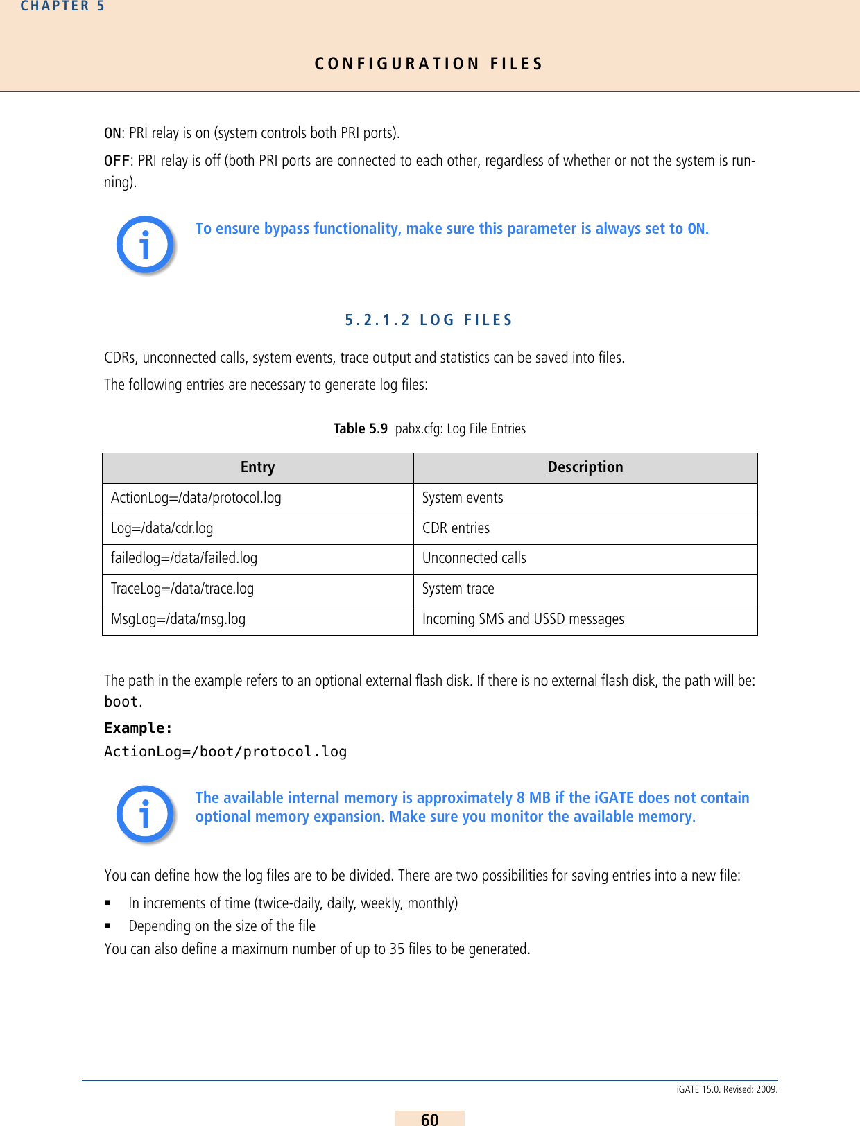
![CONFIGURATION FILESCHAPTER 561iGATE 15.0. Revised: 2009.A dash (-) appears in place of information that is to be ignored.Example 1 In the following entry, the files cdr.log and failed.log are renamed every day or whenthe file reaches 180kB, whichever comes first. Up to 7 CDR files will be saved on the system. Ifthe file size reaches 180kB on one day, the second file will have the same date. Only the runningnumber will be increased. Example 2 In the following entry, the file protocol.log is renamed every day or when the file reaches 60 kB.Up to 21 failed files will be saved on the system. Example 3 In the following entry, the file trace.log is renamed every day when the file has reached600kB. Up to seven log files will be saved on the system.Example 4 In the following entry, the statistic values are reset daily at 12:00 midnight and saved in theasr.log.Table 5.10 pabx.cfg: Log Parameters Log=/data/<file.log> <saved> <size> <number><file> The name of the log file is generated as follows: [file]yymmdd[0-9|A-Z].log.<saved> Refers to the frequency with which the file is saved. The following options are possible:halfdaily Every day at 11:59 and 23:59daily Every day at 23:59weekly Sunday at 23:59monthly The last day of the month at 23:59<size> Regardless of the value entered in <saved>, the file will be saved when the <file size> has been reached (in kB).NOTE: We recommend a file size of a multiple of 60kB.<number> Refers to the number of files that will be saved in the system (between 5 and 35) before the first file is overwritten. This setting is useful not only for limited file size, but also for files that store events. Normally size can be limited for these files, e.g. 5 files of 1MB each. If the fifth file is full, the first one will automatically be overwritten.Log=/data/cdr.log daily 180 7failedlog=/data/failed.log daily 180 7ActionLog=/data/protocol.log daily 60 21TraceLog=/data/trace.log daily 600 7StatisticTime=/data/asr.log 00:00 11111111](https://usermanual.wiki/Teles-Informationstechnologien/GSM32VOIPUS/User-Guide-1224551-Page-61.png)
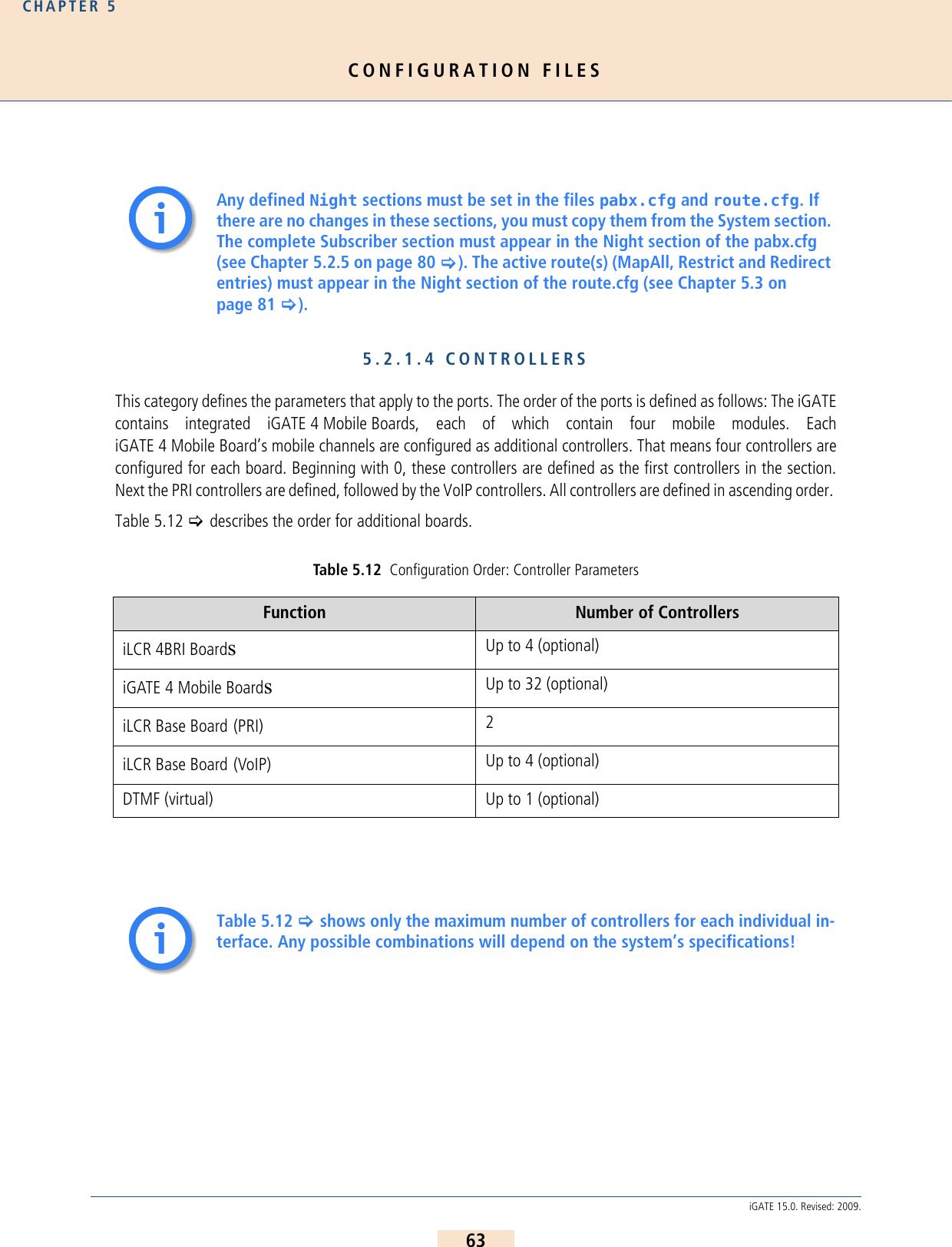
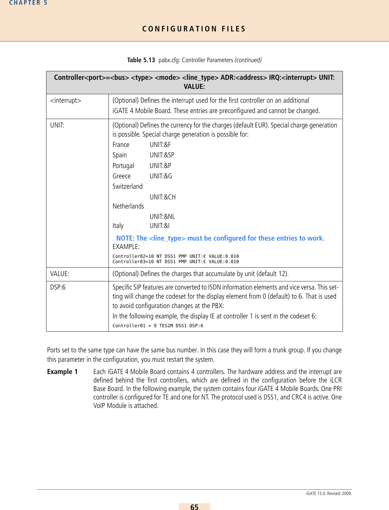
![CONFIGURATION FILESCHAPTER 564iGATE 15.0. Revised: 2009.The individual ports are defined with the following parameter: Table 5.13 pabx.cfg: Controller Parameters Controller<port>=<bus> <type> <mode> <line_type> ADR:<address> IRQ:<interrupt> UNIT: VALUE:<port> Defines the running (physical) port number.<bus> Defines the configured (virtual) port number. In the default configuration, PRI TE ports are 9 and PRI NT ports are 10. VoIP ports are 40.<type> Defines the connection type:TES2M PRI external (terminal endpoint)NTS2M PRI internal (network termination)VOIP VoIP moduleGSM GSM portCDMA CDMA portUMTS UMTS portTE BRI external (if you change from NT to TE or vice versa, you must change the DIP switches for the respective port on the iLCR 4BRI Board)NT BRI internal DTMF virtual controller for activating DTMF tone recognition<mode> Defines the protocol variation for PRI and BRI lines:DSS1 CASR2 (only for PRI lines)<line_type> Switches CRC4 mode for PRI lines on or off:CRC4 CRC4 onDF double frame: CRC4 offAdditional entry for T1 only:T1 US Defines this controller as T1. Bear in mind that if one controller is defined as T1, all controllers must be thus defined. If you configure T1, you must also enter CHMAX[23] in the corresponding Subscriber lines.T1 EXAMPLE:MULAW=YesController00=20 TES2M DSS1 T1 US Controller01=21 NTS2M DSS1 T1 US...Subscriber00 = TRANSPARENT ROUTER CHMAX[23]Subscriber01 = TRANSPARENT ROUTER CHMAX[23]<address> (Optional) Defines the hardware address used for the first controller on an additional iGATE 4 Mobile Board. These entries are preconfigured and cannot be changed.](https://usermanual.wiki/Teles-Informationstechnologien/GSM32VOIPUS/User-Guide-1224551-Page-64.png)
![CONFIGURATION FILESCHAPTER 567iGATE 15.0. Revised: 2009.5.2.1.5 SUBSCRIBERSVarious functions for individual interfaces (ISDN or VOIP) are defined in each controller’s Subscriber line. Theorder of the subscriber lines is the same as the order of the controller lines (see Chapter 5.2.1.4 on page 63 >).Most changes become active following a restart. If it suffices to activate the configuration, this is noted in the pa-rameter description: Additional parameters for mobile controllers are described in Table 5.15 > and Table5.16 >. The parameters listed in Table 5.15 > are required for mobile controllers and those listed in Table5.16 > are optional, depending on the implementation scenario.Required Mobile ParametersSpecific settings for each mobile interface appear in square brackets behind the keywords GSM, UMTS or CDMA.These parameters are separated with a comma.Table 5.14 pabx.cfg: Subscriber Parameters Subscriber<port>=<list><port> Defines the running (physical) port number.The <list> variable may contain one or more of the following keywords:DEFAULT The standard configuration will be used. No other parameters in this table are set.TRANSPARENT ROUTER Only the number is sent as caller ID (without the virtual port address). Activate configuration suffices to activate changes.CASR2[<name>] Activates the profile defined in the corresponding [CASR2] section.ALARM Activates the monitoring mode for the respective port. If a relevant error occurs at the port, a remote call is placed to the number defined in RemoteCallBack. Activate configuration suffices to activate changes.SWITCH Changes internal port handling. In the default configuration, the VoIP control-ler is set to NT. You can use this parameter to change it from NT to TE. Restart the system to activate the changes.CHMAX[xx] Defines the number of channels per VoIP controller (VoIP Module), e.g. 16 or for the virtual DTMF controller. This figure must be entered in double digits. A maximum of six concurrent channels are possible for DTMF recognition.NOTE: If all six channels are used, no PPP dialup or remote access via ISDN is possible.DTMF[<sec>,/<dir>/<file>] Please refer to Chapter 11.2.1.1 >.](https://usermanual.wiki/Teles-Informationstechnologien/GSM32VOIPUS/User-Guide-1224551-Page-67.png)
![CONFIGURATION FILESCHAPTER 568iGATE 15.0. Revised: 2009.The following parameters are required: Table 5.15 Required Parameters in pabx.cfg Subscriber<port>=<type>[<pin>,<lain>,<SMSC>,<sim>,<loudGSM>,<loudPCM>,SIM<x>,...]<port> Defines the running (physical) port number.<type> Defines whether a GSM, CDMA or UMTS module is used.<pin> Defines the SIM card’s PIN. The PIN is always four digits. If no PIN is defined for a SIM card, the PIN 0000 must be used.NOTE: An error message appears in the protocol.log file when a PIN is in-correctly configured.<lain> Defines the LAIN (Local Area Identification Number) – the mobile network to be used. This prevents roaming into another mobile network. The LAIN is always five digits. If the LAIN is set at 00000, roaming will not be prevented. The LAIN configuration prevents accidental logon of the SIM card with another network and the use of false SIM cards.<SMSC> Defines the SMS center’s access number. The number must always begin with + and the country code.<SIM> Defines the SIM card to be used. You can enter the values 1, 2, 3, 4, 5, 6 (optional when using the 24 SIM card carrier). Default 1. Do not change the default entry if you use the parameter SIM4 or SIMS. Activate configuration suffices to activate changes.NOTE: Please see the example following Table 5.16 > for information on numbering SIM cards.](https://usermanual.wiki/Teles-Informationstechnologien/GSM32VOIPUS/User-Guide-1224551-Page-68.png)
![CONFIGURATION FILESCHAPTER 569iGATE 15.0. Revised: 2009.Optional Mobile ParametersIn addition to the usual parameters, you can enter the following optional mobile parameters. Separate each pa-rameter with a comma. <loudGSM> Defines the volume level for the mobile line. The values 0 to 3 are possible. 0 is loudest and 3 is the least loud.Activating echo cancellation (for GSM modules only):Depending on the base station (BTS) one of three algorithms will work for this feature. The algorithms must be tested during activation to determine which one fits the base station type.The following values are added to the volume setting:- 16 -> algorithm 1 - 32 -> algorithm 3 - 48 -> algorithm 6 EXAMPLE 1: If the volume level is set at 1, and algorithm 1 is used for echo cancellation, the configuration for <loudGSM> is 17:Subscriber00=… GSM[0000,00000,+000000,1,17,1,SIM4] …EXAMPLE 2: If the volume level is set at 2, and algorithm 6 is used for echo cancellation, the configuration for <loudGSM> is 50:Subscriber00=… GSM[0000,00000,+000000,1,50,1,SIM4] …<loudPCM> Defines the volume level to the fixed network. The values 0 to 7 are possible. 7 is loudest and 0 is the least loud.SIM4 Defines the SIM-card carrier used. The number entered (4) refers to the number of slots. The SIM-cards can be distributed among the 4 mobile channels at will.NOTE: This parameter cannot be used in combination with SIM24 or SIMS.SIM24 Defines the SIM-card carrier used. The number entered (24) refers to the number of slots. The SIM-cards can be distributed among the 4 mobile channels at will.NOTE: This parameter cannot be used in combination with SIM4 or SIMS.Table 5.16 Optional Parameters in pabx.cfg Optional Mobile ParametersIMSIThis keyword causes the IMSIs to be recorded in each CDR. This parameter appears after SIM<x>. Activate configuration suffices to activate changes.Table 5.15 Required Parameters in pabx.cfg (continued)Subscriber<port>=<type>[<pin>,<lain>,<SMSC>,<sim>,<loudGSM>,<loudPCM>,SIM<x>,...]](https://usermanual.wiki/Teles-Informationstechnologien/GSM32VOIPUS/User-Guide-1224551-Page-69.png)
![CONFIGURATION FILESCHAPTER 570iGATE 15.0. Revised: 2009.SIMSDefine this keyword to connect the system to a vGATE. <sim> must be set to 1 in the appropriate mobile controller Subscriber line. NOTE: This parameter cannot be used with the following parameters: SIM24 or SIM4. Bear in mind that no SIM-card carrier is to be inserted in the iGATE.EXAMPLE: Subscriber00=TRANSPARENT ROUTER GSM[0000,00000,<SMSC>,1,1,1,SIMS]BAND(<int>)For iGATE 4 UMTS Boards with module type MC8755V only:Defines the mobile standard used and (<int>) can have the following values: 0 = autonegotiation (default)1 = UMTS3 = GSMFor GSM modules:Defines the GSM frequency band and (<int>) can have the following values:1 = Mono-band mode 850MHz (Q24CL001 modules only)2 = Mono-band mode 900MHz (Q24CL001 modules only)3 = Mono-band mode 1800MHz (Q24CL001 modules only)4 = Mono-band mode 1900MHz (Q24CL001 modules only)5 = Dual-band mode 850/1900MHz (Q24CL001 and GE864-QUAD modules)6 = Dual-band mode 900/1800MHz (Q24CL001 and GE864-QUAD modules)7 = Dual-band mode 900/1900MHz (Q24CL001 and GE864-QUAD modules)8 = Dual-band mode 850/1800MHz (GE864-QUAD modules only)After changing the band settings, you must restart the system to activate the changes.NOTE: The BAND parameter can only be used with quad-band GSM module-type Q24CL001. These quad-band GSM modules are available as of hardware revision 1.61 (May, 2007). There is no default band setting! If there is no BAND configuration in the pabx.cfg when the system is started, the last band stored on the module will be used. This can cause the system to attempt to register the SIM with the wrong GSM band.BNDS<int>For iGATE 4 UMTS Boards with module type UC864-G only:Selects the UMTS or GSM or auto network0 = auto (default)1 = GSM2 = UMTS Table 5.16 Optional Parameters in pabx.cfg (continued)Optional Mobile Parameters](https://usermanual.wiki/Teles-Informationstechnologien/GSM32VOIPUS/User-Guide-1224551-Page-70.png)
![CONFIGURATION FILESCHAPTER 571iGATE 15.0. Revised: 2009.BNDU<int>For iGATE 4 UMTS Boards with module type UC864-G only:Configures BAND selection in the UMTS network0 = 850/1900/2100 MHz (default)1 = 850 MHz2 = 1900 MHz3 = 2100 MHzEVL(<int>)For GSM module type Q24CL001 only:Specifies the switch’s maximum attenuation. 0 = 31 db (default)1 = 29 db2 = 27 db3 = 25 db...15=1 dbThis option is available when echo cancelation 17 is defined in loudGSM.EXAMPLE:Subscriber12 = TRANSPARENT ROUTER GSM[0000,00000,+49111111,1,17,1,SIM4,IMSI,EVL(10),EST(1)] ALARMEST(<int>)For GSM module type Q24CL001 only:Specifies the interval between attenuation and no attenuation. 0 = 1 db 1 = 2 db2 = 3 db3 = 4 db (default)This option is available when echo cancelation 17 is defined in loudGSM.EXAMPLE:Subscriber12 = TRANSPARENT ROUTER GSM[0000,00000,+49111111,1,17,1,SIM4,IMSI,EVL(10),EST(1)] ALARMETR(<int>)For GSM module type Q24CL001 only:Enter a value between 0 and 31 (default 10) to define the relative threshold between maximum and mini-mum energy information. This option is available when echo cancelation 17 is defined in loudGSM. Table 5.16 Optional Parameters in pabx.cfg (continued)Optional Mobile Parameters](https://usermanual.wiki/Teles-Informationstechnologien/GSM32VOIPUS/User-Guide-1224551-Page-71.png)
![CONFIGURATION FILESCHAPTER 572iGATE 15.0. Revised: 2009.Example: The following example has two groups of SIMs. Different SMS center numbers are set for con-trollers 00-07 and 08-15. SIM 24 Carriers are used, so that several SIMs can be used for eachmobile channel. SIM-position 1 is used in the SIM 24 Carrier for the first, third and fourthiGATE 4 Mobile Board (SIM-slots 0-3). SIM-position 2 is used in the secondiGATE 4 Mobile Board SIM-slots 4-7). Routing to mobile is based on the LAIN (CHADDR): ETM(<int>)For GSM module type Q24CL001 only:Enter a value between 0 and 31 (default 7) to define the threshold of maximum energy information. This option is available when echo cancelation 17 is defined in loudGSM. Subscriber00 = TRANSPARENT ROUTER GSM[0000,00000,+491555555,1,1,1,SIM24,IMSI] CHADDR ALARM NEXTSubscriber01 = TRANSPARENT ROUTER GSM[0000,00000,+491555555,1,1,1,SIM24,IMSI] CHADDR ALARM Subscriber02 = TRANSPARENT ROUTER GSM[0000,00000,+491555555,1,1,1,SIM24,IMSI] CHADDR ALARMSubscriber03 = TRANSPARENT ROUTER GSM[0000,00000,+491555555,1,1,1,SIM24,IMSI] CHADDR ALARMSubscriber04 = TRANSPARENT ROUTER GSM[0000,00000,+491555555,2,1,1,SIM24,IMSI] CHADDR ALARMSubscriber05 = TRANSPARENT ROUTER GSM[0000,00000,+491555555,2,1,1,SIM24,IMSI] CHADDR ALARM Subscriber06 = TRANSPARENT ROUTER GSM[0000,00000,+491555555,2,1,1,SIM24,IMSI] CHADDR ALARMSubscriber07 = TRANSPARENT ROUTER GSM[0000,00000,+491555555,2,1,1,SIM24,IMSI] CHADDR ALARMSubscriber08 = TRANSPARENT ROUTER GSM[0000,00000,+491666666,1,1,1,SIM24,IMSI] CHADDR ALARM NEXTSubscriber09 = TRANSPARENT ROUTER GSM[0000,00000,+491666666,1,1,1,SIM24,IMSI] CHADDR ALARM Subscriber10 = TRANSPARENT ROUTER GSM[0000,00000,+491666666,1,1,1,SIM24,IMSI] CHADDR ALARMSubscriber11 = TRANSPARENT ROUTER GSM[0000,00000,+491666666,1,1,1,SIM24,IMSI] CHADDR ALARMSubscriber12 = TRANSPARENT ROUTER GSM[0000,00000,+491666666,1,1,1,SIM24,IMSI] CHADDR ALARMSubscriber13 = TRANSPARENT ROUTER GSM[0000,00000,+491666666,1,1,1,SIM24,IMSI] CHADDR ALARM Subscriber14 = TRANSPARENT ROUTER GSM[0000,00000,+491666666,1,1,1,SIM24,IMSI] CHADDR ALARMSubscriber15 = TRANSPARENT ROUTER GSM[0000,00000,+491666666,1,1,1,SIM24,IMSI] CHADDR ALARMSubscriber16 = TRANSPARENT ROUTER ALARMSubscriber17 = TRANSPARENT ROUTER ALARMSubscriber18 = TRANSPARENT ROUTER SWITCH CHMAX[16] ALARMFor a detailed description of the configuration of the iGATE 4 Mobile Board, includ-ing the keywords CHADDR, NEXT, LIMIT and CONTINUE, please refer to Chapter 7 on page 101 >.Table 5.16 Optional Parameters in pabx.cfg (continued)Optional Mobile Parametersii](https://usermanual.wiki/Teles-Informationstechnologien/GSM32VOIPUS/User-Guide-1224551-Page-72.png)
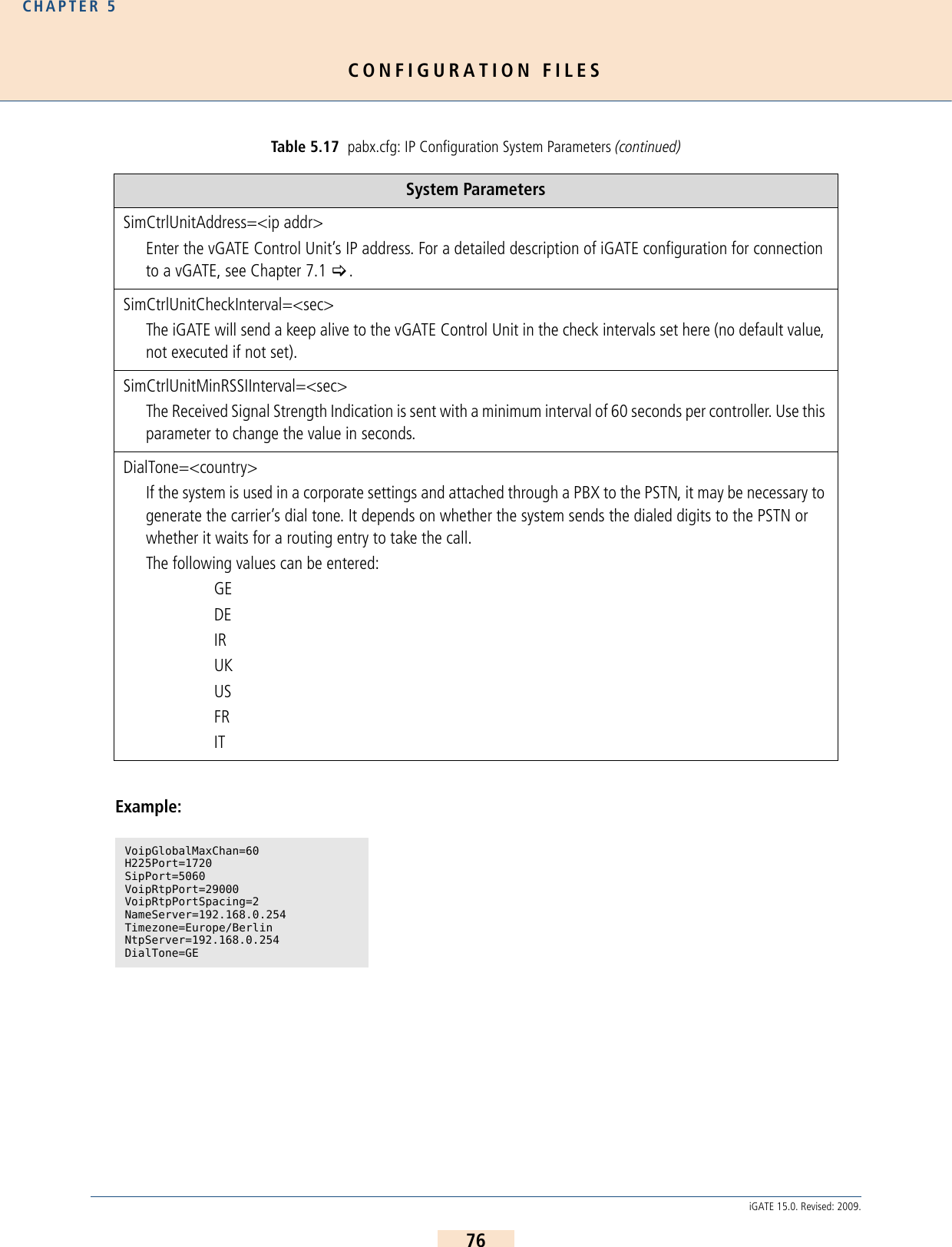
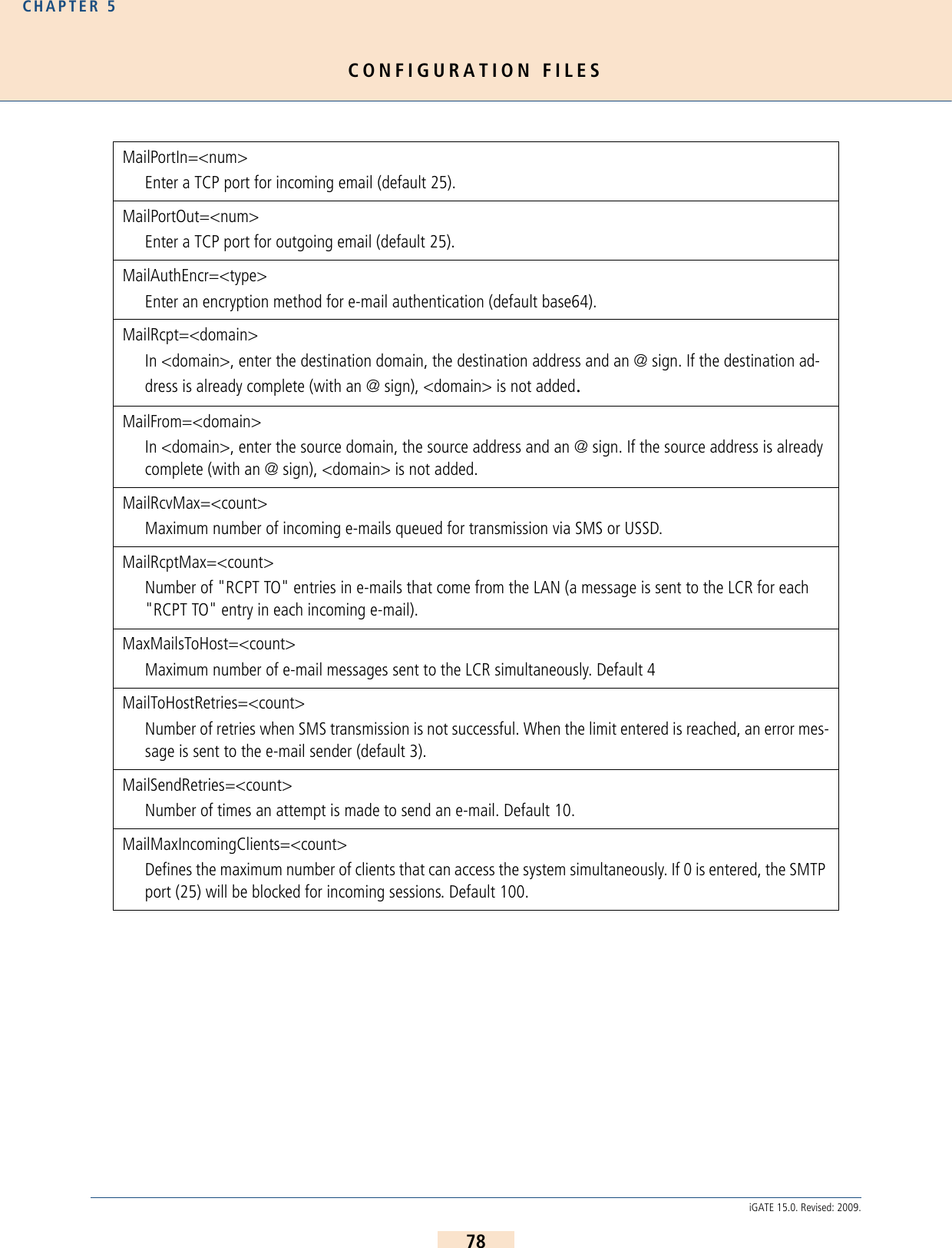
![CONFIGURATION FILESCHAPTER 577iGATE 15.0. Revised: 2009.5.2.2 SMTP-CLIENT CONFIGURATIONThe following entries in the pabx.cfg’s [Mail] section are used to send e-mail messages from the iGATE. The con-nection to the SMTP server can be used to send CDR files, incoming SMS to an e-mail account or alarm messages.The following features are possible:Sending SMS via e-mailReceiving SMS in an e-mail, SMS or in a fileSending and receiving USSD text messagesDisplaying incoming calls via e-mailSetting up connections using e-mailSending automatic SMS for unconnected callsSending CDRs via e-mailSending alarm messages via e-mailThere is no internal time generation for the system when the power is interrupted. That means the default time is used when the system is restarted or rebooted! Therefore it is important to set the system time with an NTP server. If the system is connected via BRI or PRI, a clock may come from the network connected to the cor-responding port. Enter !TIME in the pabx.cfg’s subscriber line and then activate the configuration to block this clock.You must restart the system after making changes to activate the settings.SmtpServer=<ip addr>In <ip addr>, enter the IP address of the destination SMTP server that is to receive the e-mail messages. MailUserIn=<username>Enter a username for incoming e-mail authentication.MailUserOut=<username>Enter a username for outgoing e-mail authentication.MailPwdIn=<password>Enter a password for incoming e-mail authentication.MailPwdOut=<password>Enter a password for outgoing e-mail authentication.iiii](https://usermanual.wiki/Teles-Informationstechnologien/GSM32VOIPUS/User-Guide-1224551-Page-77.png)
![CONFIGURATION FILESCHAPTER 579iGATE 15.0. Revised: 2009.Example:Sending Alarm Messages via E-mailWith the appropriate configuration, you can send e-mails containing alarm messages that are written into the logfile. The sender is given as alarm and the system’s name appears in the subject box. The text box contains thealarm message. The following entry in the configuration file activates this function: 5.2.3 NUMBER PORTABILITY SETTINGSThe [NumberPortability] section includes the parameters necessary for communication with the database server.For a description of the functionality and configuration of this feature, please see Chapter 11.6 >.MailTcpRcvTimeout=<sec>Defines the number of seconds after which a session will be terminated following a possible receiving error in the data stream. Default 0 (immediately).MailTcpSndTimeout=<sec>Defines the number of seconds after which a session will be terminated following a possible transmission error in the data stream. Default 0 (immediately).MailAllowedPeers=<ip addr>Defines IP addresses from which incoming SMTP connections will be accepted. Separate IP addresses with a space. If a dash (-) is entered, the SMTP port (25) will be blocked for incoming sessions. If this parameter is left empty (default), incoming connections will be accepted from all IP addresses.MailPropPort=<num>Enter the port number for a TELES proprietary mail protocol.[Mail]SmtpServer=172.16.0.10MailRcpt=teles.deMailFrom=172.16.0.100MailRcvMax=300MailRcptMax=50MaxMailsToHost=2MailToHostRetries=10MailSendRetries=10MailAllowedPeers=172.16.0.10...ActionLog=/data/protocol.log daily 1000 5 @<e-mail account>...You must restart the system after making changes to activate the settings.ii](https://usermanual.wiki/Teles-Informationstechnologien/GSM32VOIPUS/User-Guide-1224551-Page-79.png)
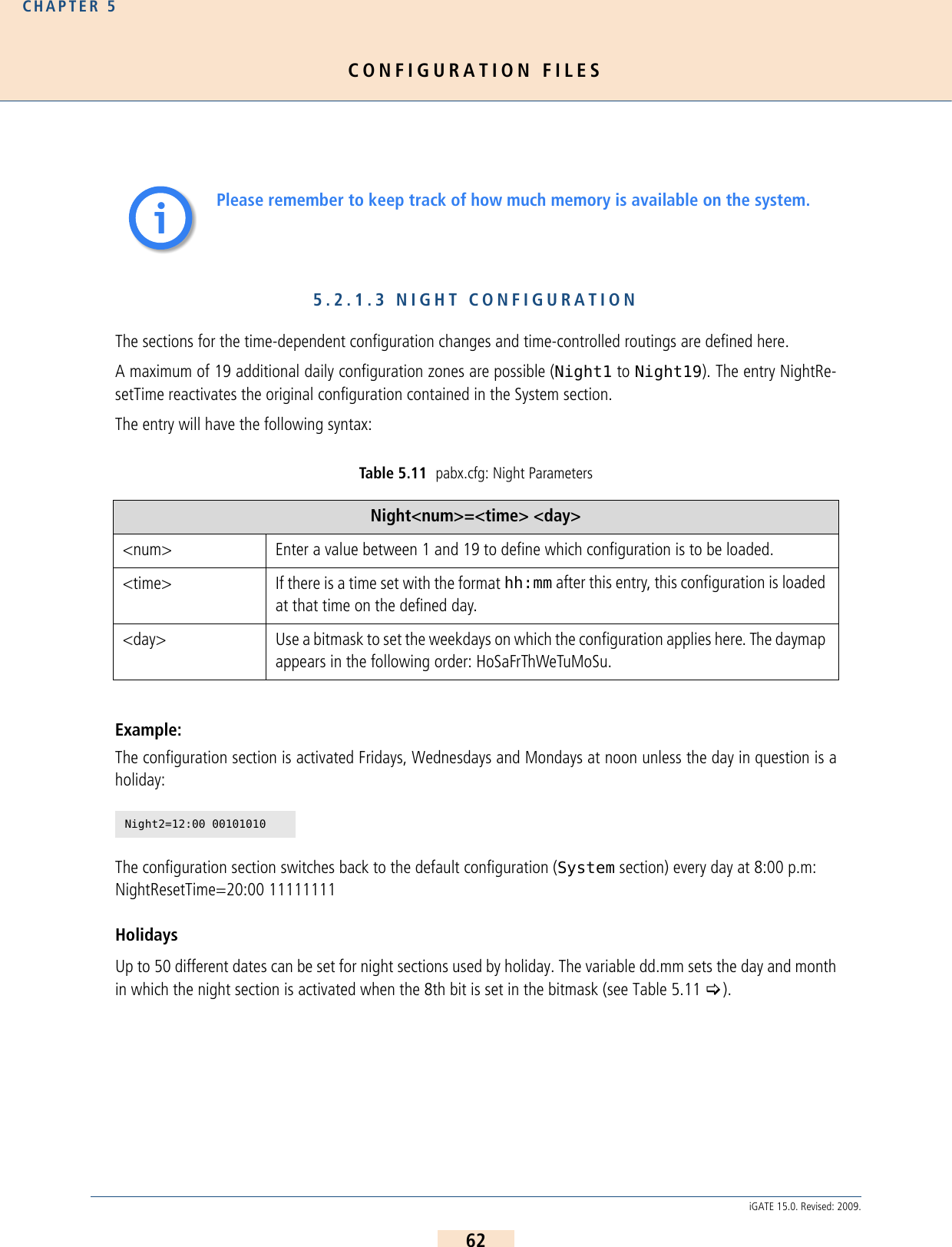
![CONFIGURATION FILESCHAPTER 580iGATE 15.0. Revised: 2009.Example:5.2.4 SNMP SETTINGSThe Simple Network Management Protocol facilitates network management and monitoring of iGATE network de-vices and their functions. For a detailed description of SNMP configuration, please refer to Chapter 12.3 >.5.2.5 TIME-CONTROLLED CONFIGURATION SETTINGSThe [Night<num>] section is reserved for prospective time-controlled configuration changes. In the pabx.cfgfile, the Night sections contain all of the system’s Subscriber entries.MNPQAddress=<ip addr>Enter the IP address to which the number portability query is to be sent. The service comes from an external provider. It is also used as the iMNP address if the parameter MNPQSum=Yes is set.MNPQPort=<port>Enter the port to which the number portability query is to be sent.MNPQAddress2=<ip addr>Enter the IP address to which the second number portability query is to be sent when ! appears in the map-ping entry. A second database will then be queried, for example if the first on is not online.MNPQPort2=<port>Enter the port to which the second number portability query is to be sent.MNPQSum=<mode>This parameter must be activated (Yes) if a iMNP is used.E2EMRSAddress=<ip addr>Enter the IP address to which the number portability query is to be sent. The service comes from an external provider.E2EMRSPort=<port>Enter the port to which the number portability query is to be sent. [NumberPortability]MNPQAddress=172.16.0.100MNPQPort=9003MNPQSum=YesYou must restart the system after making changes to activate the settings.ii](https://usermanual.wiki/Teles-Informationstechnologien/GSM32VOIPUS/User-Guide-1224551-Page-80.png)
![CONFIGURATION FILESCHAPTER 581iGATE 15.0. Revised: 2009.Individual SIM-card positions can be configured here. For a detailed description of time-controlled SIM switching,please refer to Chapter 7.10 >5.2.6 .CASR2 SETTINGSIf you are working with Channel Associated Signaling, you must activate a CAS profile in the relevant Control-ler and Subscriber entries and define a profile for each Subscriber entry in a separate[CASR2:<name>] section. Generally you will need to set only the country code 55 for Brazil. The default country code is 0, which sets the ITU-T standard. Example:5.3 CONFIGURATION FILE ROUTE.CFGThe system’s routing information is saved in the route.cfg. The file contains the following sections: [System]Contains all routing entries (MapAll, Restrict, Redirect) that are to be active when the default configurationis used.[Night<num>]Contains all routing entries (MapAll, Restrict, Redirect), and VoIP, gatekeeper and registrar profiles thatare to be active with the defined time configuration. Bear in mind that you must also copy all routing andprofile settings that may already appear in the das System section or in the individual profile sections, evenif they do not change![VoIP:<name>]Contains all settings necessary for communication with the VoIP peer.[GateKeeper:<name>]Contains all settings for the gatekeeper. This profile is then assigned to the VoIP profiles.[Registrar:<name>]Contains all settings to register with the registrar.Controller00=9 TES2M CASR2...Subscriber00 = TRANSPARENT ROUTER CASR2[BRAZIL1] ALARMSubscriber01 = TRANSPARENT ROUTER CASR2[BRAZIL2] ALARM...[CASR2:BRAZIL1]CountryCode=55[CASR2:BRAZIL2]CountryCode=55You must restart the system after making changes to activate the settings.ii](https://usermanual.wiki/Teles-Informationstechnologien/GSM32VOIPUS/User-Guide-1224551-Page-81.png)
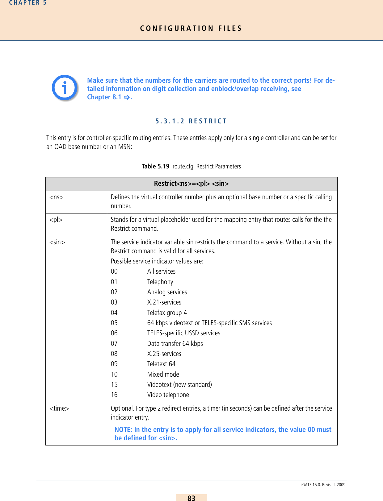
![CONFIGURATION FILESCHAPTER 582iGATE 15.0. Revised: 2009.5.3.1 ENTRIES IN THE [SYSTEM] SECTIONThe[System]section contains the following entries.5.3.1.1 MAPPINGMapping entries begin with the keyword MapAll. Example: In the following example, all mobile calls with the prefix 01555 are transmitted to the mobilecontrollers (20). All international calls are sent to the VoIP carrier (40) with the profile nameDF. All national calls are sent to the PRI controller with the number 9: If CHADDR appears in the mobile port’s Subscriber lines, the entry will look like this:MapAll<num>=<lain><num>Example: In the following example, all calls with the prefixes 01555 and 01556 are sent to the mobile con-trollers with the LAIN 26212. All calls with the prefixes 01444 and 01445 are sent to the mobilecontrollers with the LAIN 26213. Digit collection is activated:Table 5.18 route.cfg: Map Parameters MapAll<direct>=<num> <mode><direct> Defines the prefix or telephone number for which the entry applies.<num> Defines the following in the order given:Destination port’s controller numberOptional VoIP profile name followed by a colon if the call is terminated via VoIPOptional prefixPart of the number on the left that is to appear on the rightThe special symbol ? may be used as a wildcard to represent any digit.<mode> VOICE Applies for calls with the service indicator voice (default).DATA Applies for calls with the service indicator data.MapAll01555=|2001555<<14MapAll00=40DF:00MapAll0=90MapAll01555=|2621201555<<17MapAll01556=|2621201556<<17MapAll01444=|2621301444<<17MapAll01445=|2621301445<<17](https://usermanual.wiki/Teles-Informationstechnologien/GSM32VOIPUS/User-Guide-1224551-Page-82.png)
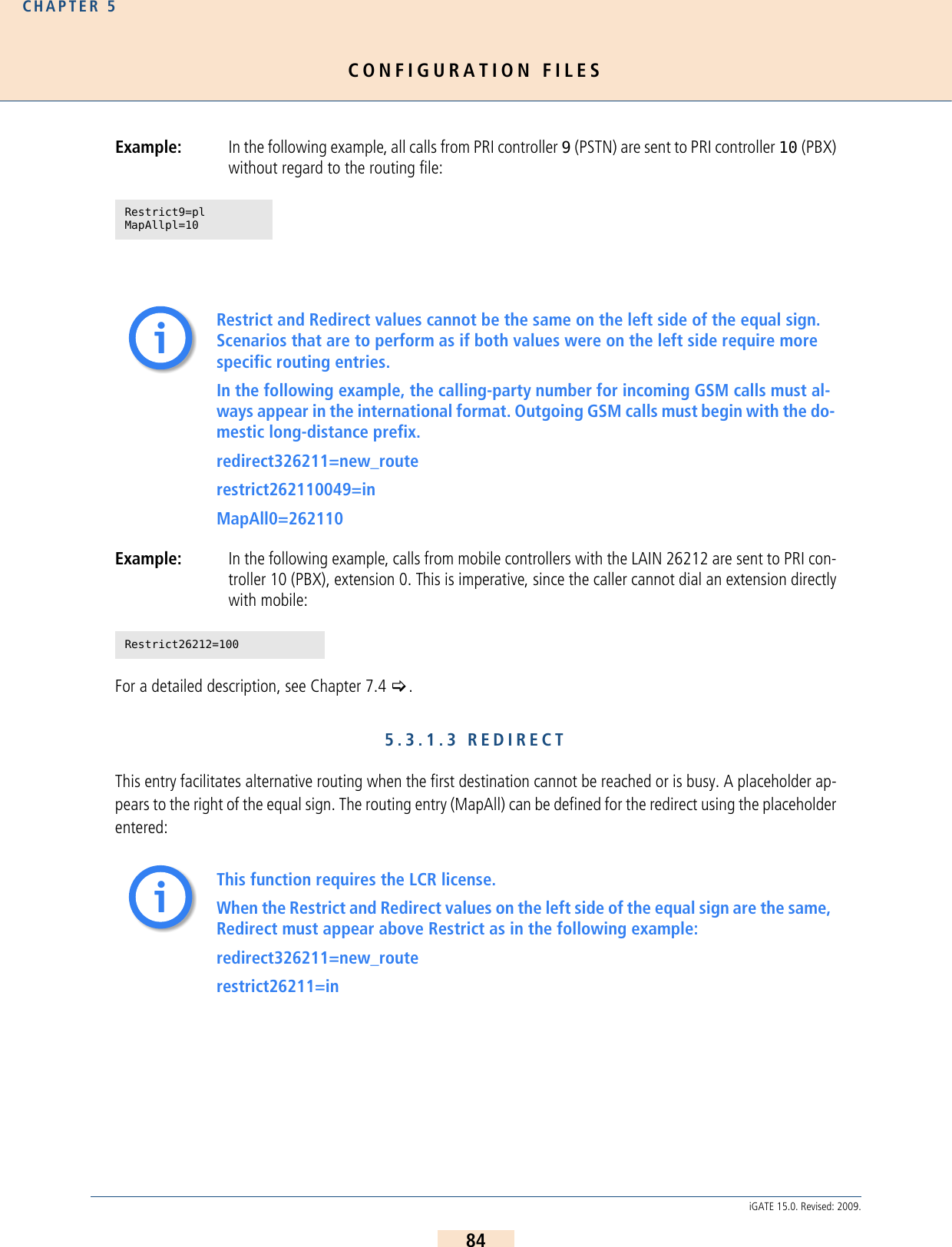
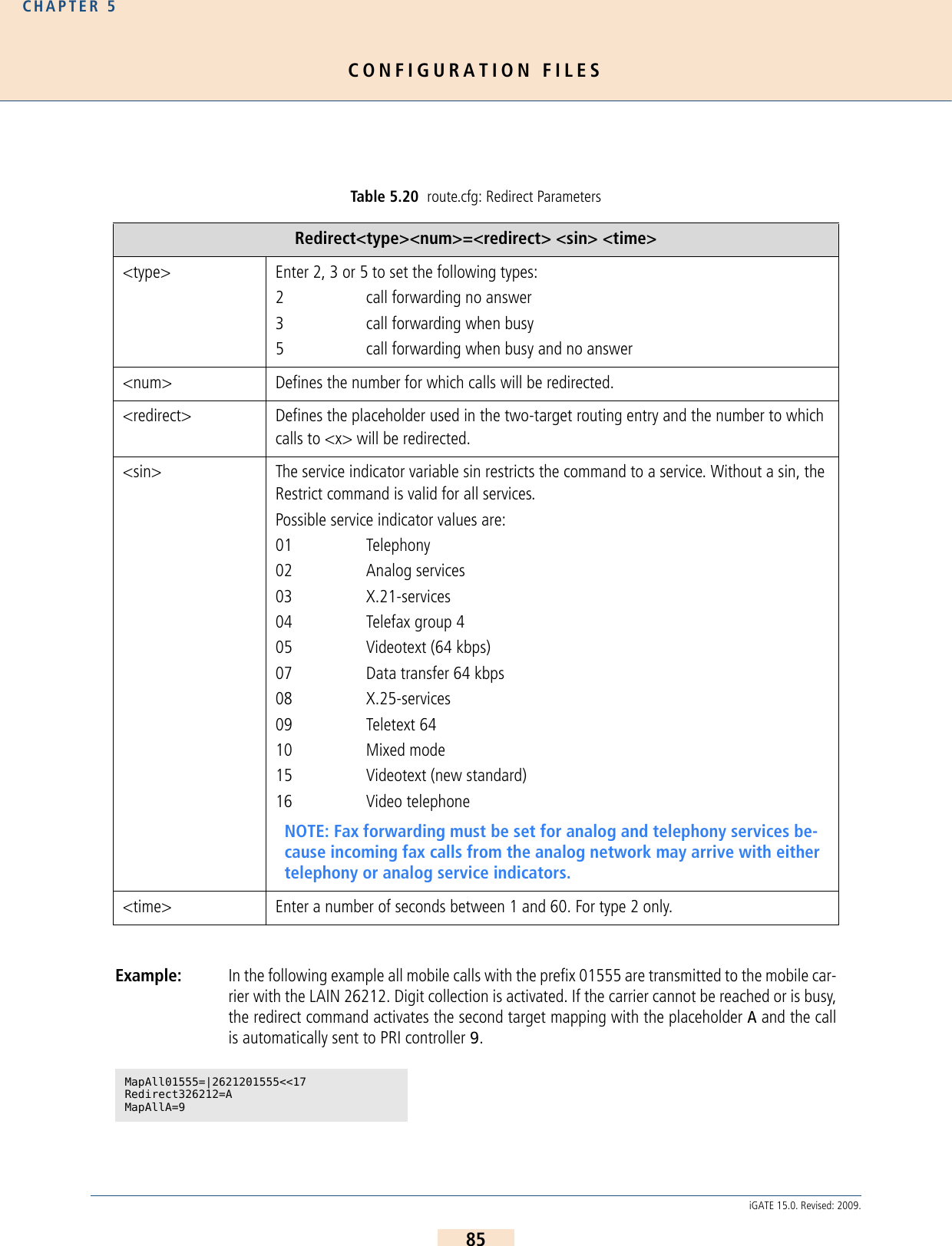
![CONFIGURATION FILESCHAPTER 586iGATE 15.0. Revised: 2009.Excluding Busy Calls or Specific Cause Values from RedirectDefines a hexadecimal cause value according to DSS1. When connections to the destination are rejected becauseof the reason defined by the cause value, the iGATE sends a busy signal to the attached PBX. Alternative routingis not carried out.To avoid second-choice routings when the called-party number is busy, set the following parameter in the first-choice port’s Subscriber line in the pabx.cfg:Example: In the following example, all outgoing calls over controller 04 are rejected with the cause value91 when the called party is busy. Alternative routing is not carried out.5.3.1.4 SETTING THE TIME-CONTROLLED SECTIONSIf you use a time-configured route on the system, please see Chapter 5.2.1.3 > for a definition of individual con-figuration zones. The active route is configured in the route.cfg file.The following example contains three sections ([System], [Night1] and [Night2]), in which the route changes. Allinternational calls are sent to the VoIP carrier DF in the default configuration. Digit collection is actived. In the timespan for [Night1], these international calls are routed to VoIP carrier Ni, and in the time span for [Night2] they arerouted through the PRI controller to the carrier with the prefix 010xx. National calls are always sent to VoIP carrierDF and local calls are routed to the outside line.Example:BUSY[<cause>] Defines a hexadecimal cause value according to DSS1. When connections to the destination are rejected because of the reason defined by the cause value, the iGATE sends a busy signal to the attached PBX. Alternative routing is not carried out. You can also define a range of consecutive cause values: BUSY[<cause>,<cause>]An exclamation point (!) in front of a cause value means all cause values except the one listed. For example, BUSY[!95], means all cause values except 95 will be rejected with a busy signal.Subscriber04=....BUSY[91][System]MapAll00=|40DF:00<<24MapAll0=|40DF:0<<24MapAll?=9?[Night1]MapAll00=|40Ni:00<<24MapAll0=|40DF:0<<24MapAll?=9?[Night2]MapAll00=9010xx00MapAll0=|40DF:0<<24MapAll?=9?](https://usermanual.wiki/Teles-Informationstechnologien/GSM32VOIPUS/User-Guide-1224551-Page-86.png)
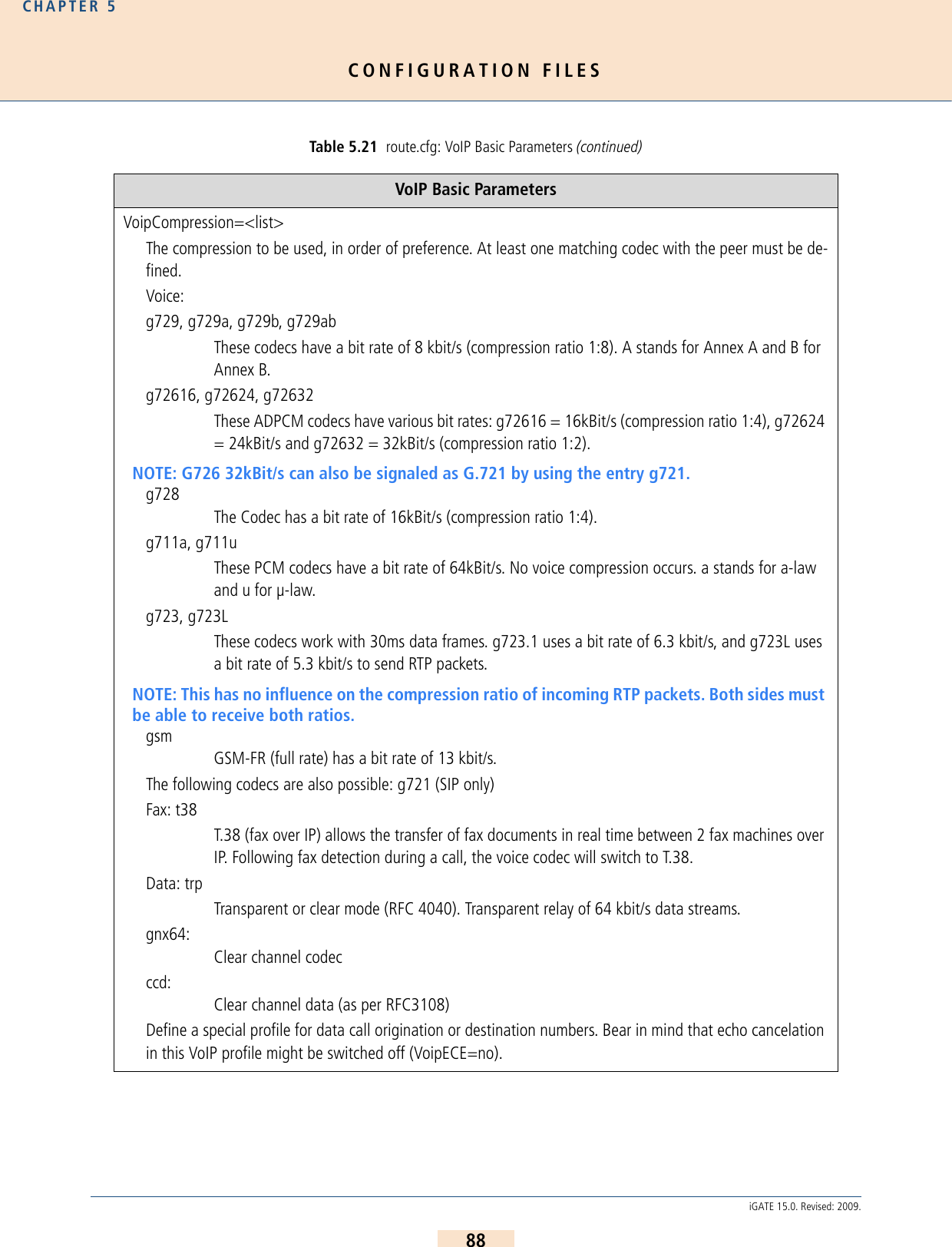
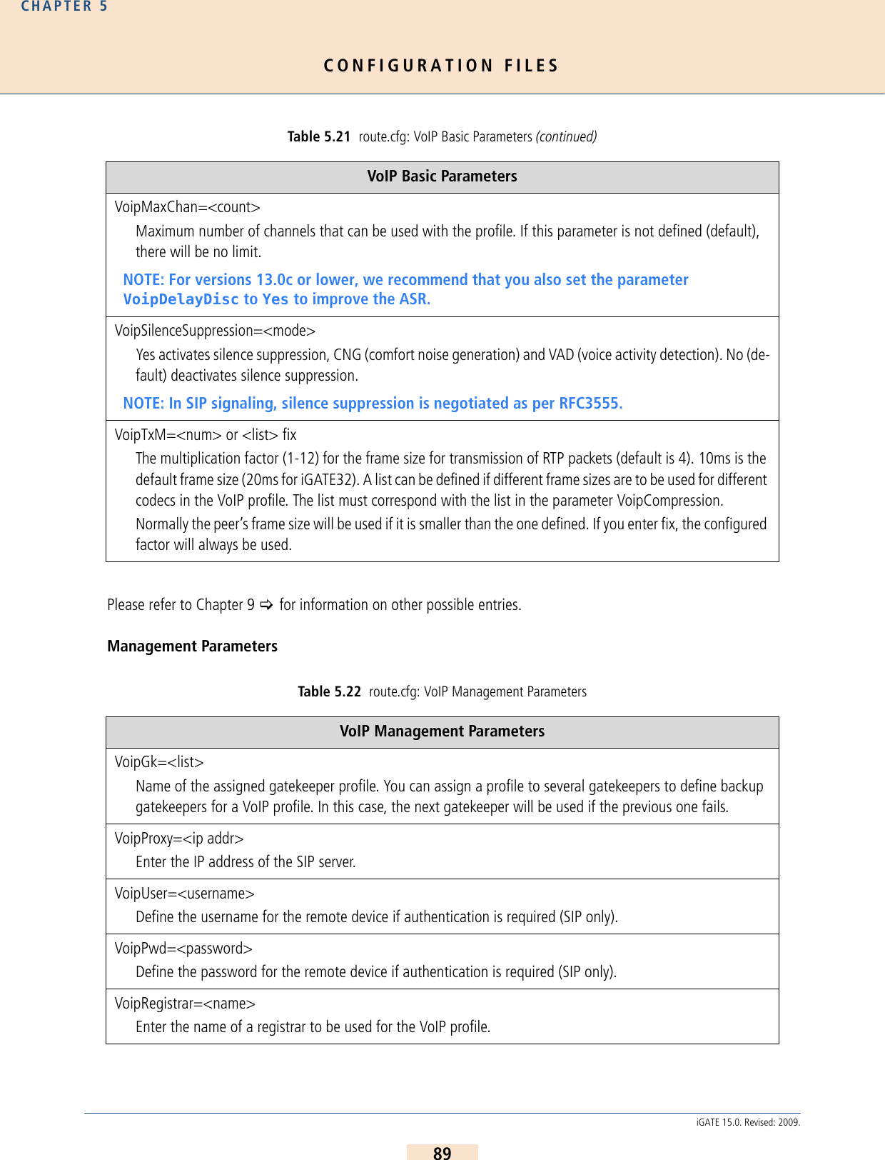
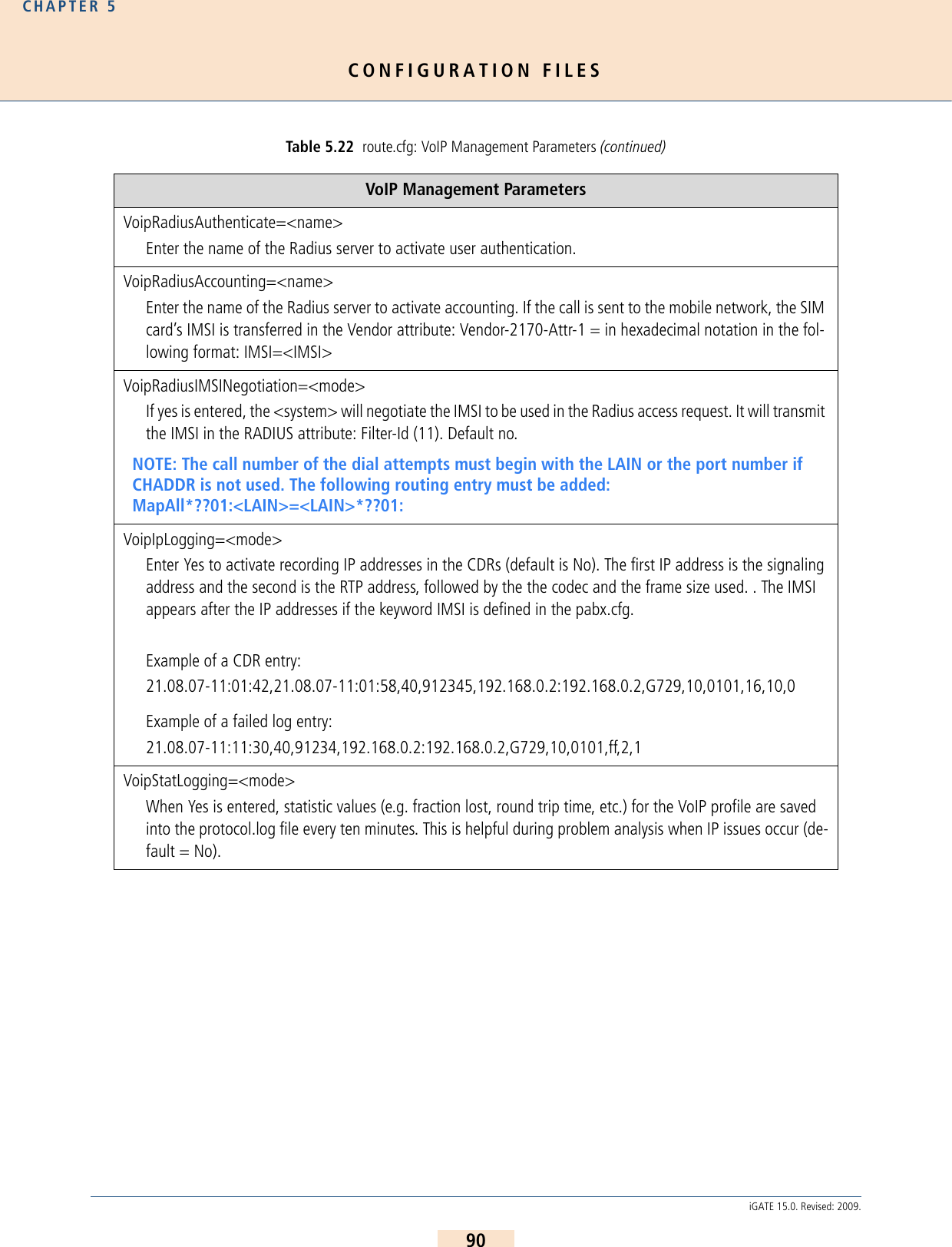
![CONFIGURATION FILESCHAPTER 587iGATE 15.0. Revised: 2009.5.3.2 VOIP PROFILESThis section includes all of the most important parameters for communication with the VoIP peer.Basic ParametersAny defined Night configurations must be set in the files pabx.cfg and route.cfg. If there are no changes in these sections, you must copy them from the System section. The complete Subscriber section must appear in the Night section of the pabx.cfg (see Chapter 5.2.5 on page 80 >). The active route must appear in the route.cfg (see Chapter 5.3 on page 81 >).Table 5.21 route.cfg: VoIP Basic Parameters VoIP Basic Parameters[Voip:<name>]Name of the routing profile. The name must begin with a letter. Use a short and meaningful name.VoipDirection=<mode>Defines the direction in which VoIP calls can be set up. Possible options: In, Out, IO, None).VoipPeerAddress=<ip addr> or <name>The peer’s IP address or name. Default is 0 (if it is not set, please set the parameter VoipIpMask to 0x00000000).VoipIpMask=<ip mask>The subnetmask is used to determine the size of the IP address range for incoming traffic. The syntax is 0x followed by the mask in hexadecimal notation. Example of a Class C mask entry: 0xffffff00. Default is 0xffffffff (only incoming traffic is accepted from the defined peer address).VoipSignalling=<int>Determines the profile’s signaling protocol for outgoing VoIP calls. In the case of incoming calls, autorecog-nition ensures that each call from the peer is accepted, regardless of the protocol: 0=H.323 (default), 1=SIP udp, 2=SIP tcp.ii](https://usermanual.wiki/Teles-Informationstechnologien/GSM32VOIPUS/User-Guide-1224551-Page-87.png)
![CONFIGURATION FILESCHAPTER 591iGATE 15.0. Revised: 2009.5.3.3 GATEKEEPER PROFILESGatekeeper profiles are used to connect the iGATE to several systems by using a gatekeeper if the protocol isH.323. It is possible to configure different gatekeepers for different destinations and to define backup gatekeepers.These gatekeeper profiles are then assigned to the VoIP profiles:Table 5.23 route.cfg: Gatekeeper Parameters Gatekeeper Parameters[Gatekeeper:<name>]Name of the gatekeeper profile.RasPort=<port>Indicates the port the gatekeeper uses (default 1719) for registration, admission and status.OwnRasPort=<port>Indicates the port the system uses (default 1719) for registration, admission and status.RasPrefix=<list>iGATE’s defined prefix(es). Use a space to separate entries.RasId=<name>The alias used for gatekeeper registration.GkId=<name>The gatekeeper’s alias.GkPwd=<name>Password to log onto the gatekeeper. If you do not use authentication, leave this entry blank.GkAdd=<ip addr>The gatekeeper’s IP address.GkTtl=<sec>Gatekeeper time to live (default 0 means infinite).GkMaxChan=<count>Max. number of channels used for this gatekeeper. If this parameter is not defined (default), there will be no limit.GkDynMaxChan=<mode>The static number of available channels in the gatekeeper profile (GkMaxChan=<count>) is replaced with a dynamic number of active mobile ports (up to the number entered in GkMaxChan) when Yes is entered here. Default is No.GkUseStun=<mode>Enter yes (default) to use the STUN values for the GK profile.](https://usermanual.wiki/Teles-Informationstechnologien/GSM32VOIPUS/User-Guide-1224551-Page-91.png)
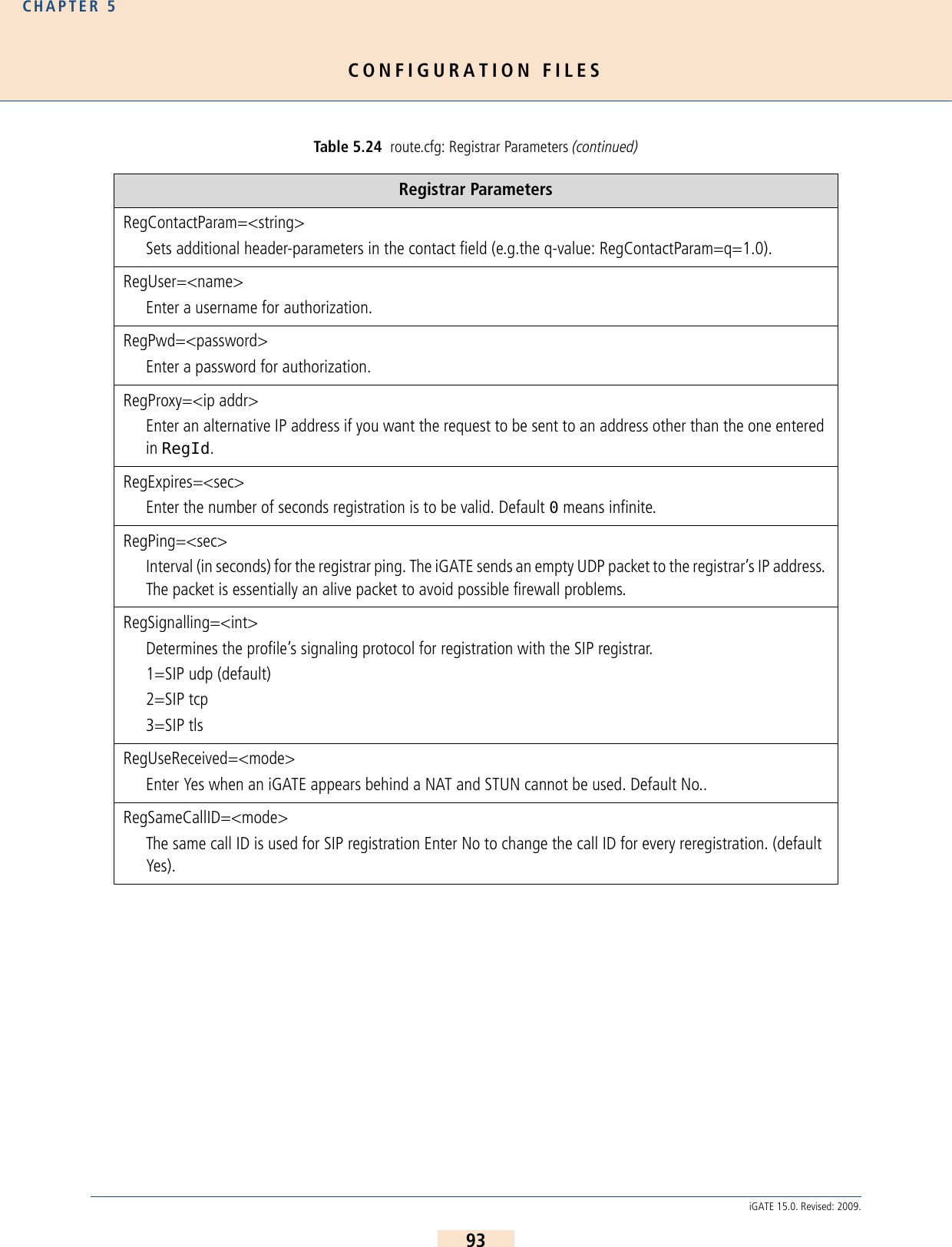
![CONFIGURATION FILESCHAPTER 592iGATE 15.0. Revised: 2009.5.3.4 REGISTRAR PROFILESRegistrar profiles are used to register the iGATE with a SIP registrar. It is possible to configure different registrarsfor different destinations and to define backup registrars. These registrar profiles are then assigned to the VoIPprofiles:GkTerminalAliasWithPrefix=<mode>Some gatekeepers may require that prefixes are listed in the Terminal Alias section. Enter Yes to activate this function; default value is No). GkTerminalTypeWithPrefix=<mode>Enter no to deactivate sending the Dialed Prefix Information in the Registration Request (default yes).GkDynRai=<mode>When yes is entered, the GK receives an RAI (resource availability indication) when a status change occurs on the available mobile channels. When no is entered, the RAI is sent with each ARQ (admission request) and DRQ (disengaged request). Default is no.GkNoResourceAvailableIndication=<mode>With this parameter the <system> will not send RAI indications to the Gatekeeper. Default No.Table 5.24 route.cfg: Registrar Parameters Registrar Parameters[Registrar:<name>]The name of the registrar profile.RegId=<name or ip addr>Host name or IP address used in the register’s request header. Bear in mind that the DNS service must be active if you enter the host name.RegOwnId=<name@ip addr/domain>Typically a host name or telephone number followed by an @ sign and a domain name or IP address. The entry used in the From: field. The default setting is RegUser@RegId.RegSameCallID=<mode>When Yes is set (default), the same caller ID is always used for SIP registration. Set No to change the caller ID for each SIP registration.RegContact=<name or ip addr>Used in the Contact: field.Table 5.23 route.cfg: Gatekeeper Parameters (continued)Gatekeeper Parameters](https://usermanual.wiki/Teles-Informationstechnologien/GSM32VOIPUS/User-Guide-1224551-Page-92.png)
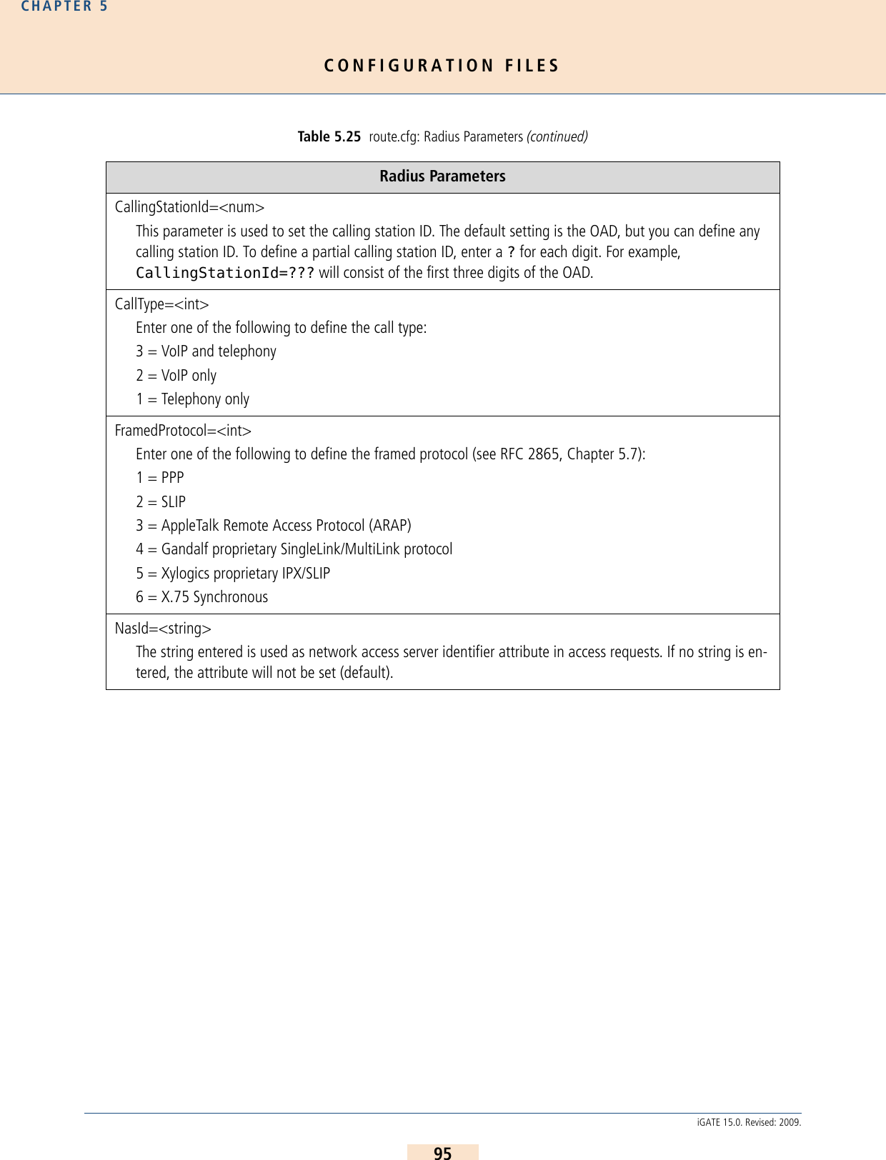
![CONFIGURATION FILESCHAPTER 594iGATE 15.0. Revised: 2009.5.3.5 RADIUS PROFILESRadius profiles are used to connect the iGATE to a Radius server. You can use a Radius server for different desti-nations and for access and/or accounting. These Radius profiles are then assigned to the VoIP profiles: Table 5.25 route.cfg: Radius Parameters Radius Parameters[Radius:<name>]The name of the Radius server profile assigned to one or more VoIP profiles.Host=<name or ip addr>Radius server’s host name or IP address. Bear in mind that the DNS service must be active if you enter the host name.User=<name>Enter a username for authorization.Password=<password>Enter a password for authorization.Secret=<secret>Enter the shared secret.OwnId=<name or ip addr>Host name or IP address used in the NAS identifier or NAS IP address (Cisco VSA gateway ID).ServiceType=<num>As defined in RFC 2865, Chapter 5.6.RequestTimeout=<sec>Number of seconds during which the request is repeated if the Radius server does not respond.RequestRetries=<count>Number of packet retries sent at one time.StopOnly=<mode>When yes is entered, only Accounting Request Messages with the status type stop are transmitted to the Radius server.AlwaysConnected=<mode>Enter No (default) to set the value for the field ConnectedTime to that of the field DisconnectedTime in accounting-stop messages when the call was not connected.](https://usermanual.wiki/Teles-Informationstechnologien/GSM32VOIPUS/User-Guide-1224551-Page-94.png)
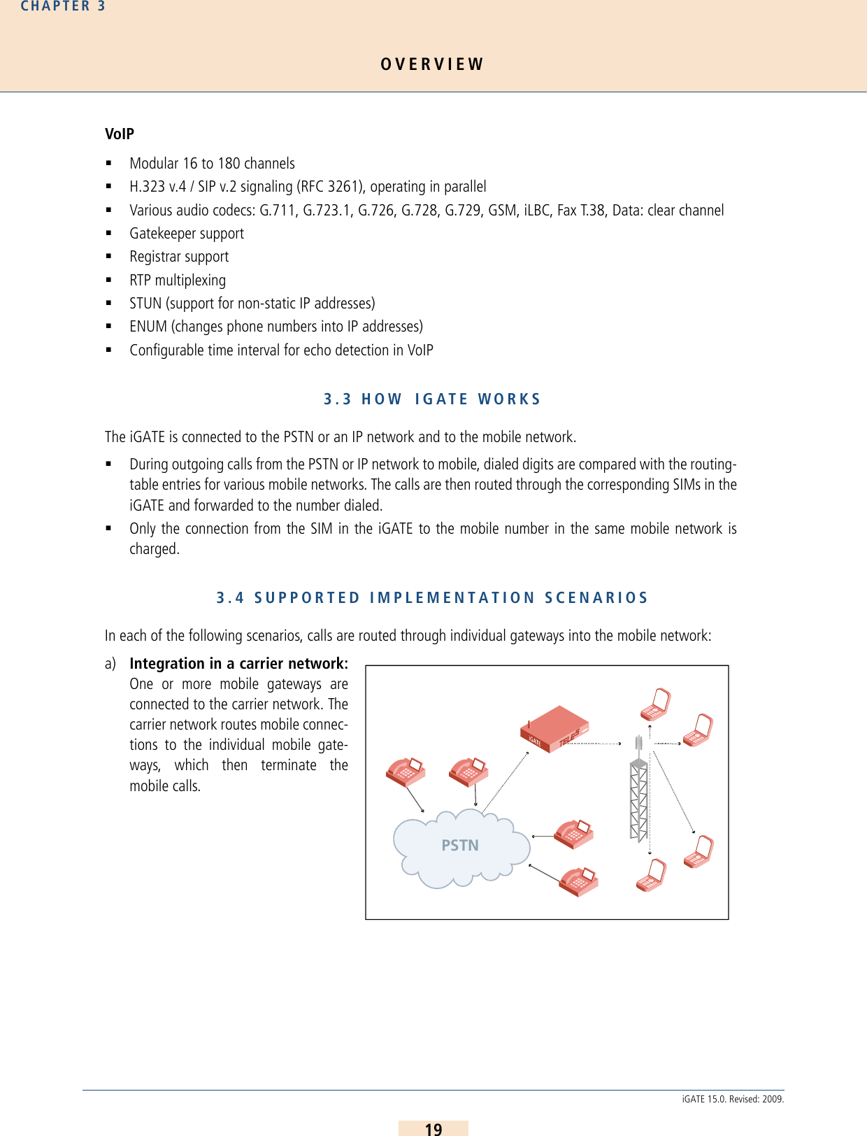
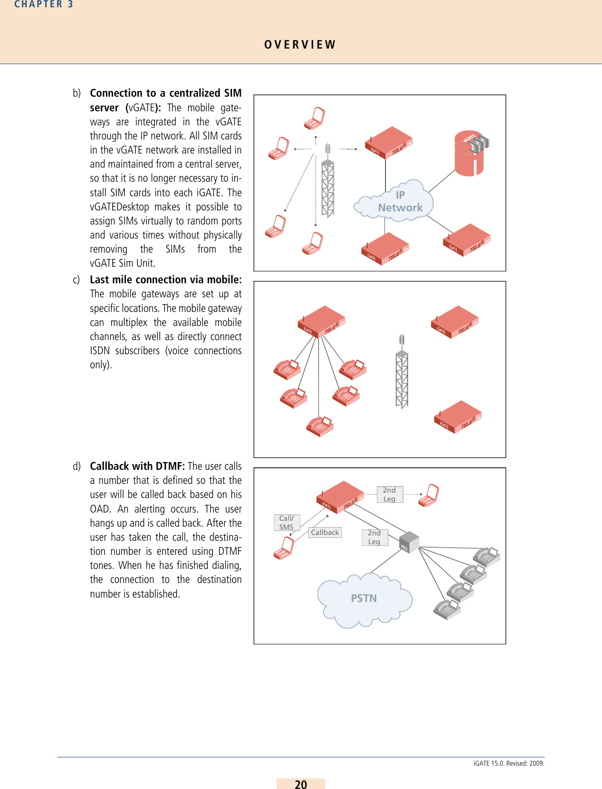
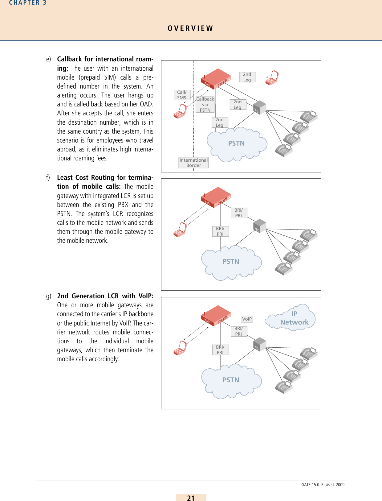
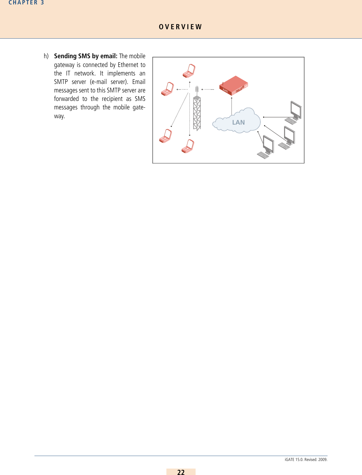
![ROUTING EXAMPLESCHAPTER 696iGATE 15.0. Revised: 2009.6 ROUTING EXAMPLES6.1 IGATE INTEGRATION IN A CARRIER NETWORKIn the following example, a iGATE32 is inte-grated in a carrier network via DSS1. It is con-nected to a vGATE and receives SIM-cardinformation from a centralized SIM-card serv-er. The IP address for the vGATE Control Unitis 172.16.0.100. The parameter SIMS is usedin SIM<x> to connect the mobile controllerwith the vGATE. All calls coming from ISDN aresent to two different mobile networks: Callswith the prefixes 01555 and 01556 are sent tothe carrier with the LAIN 26212 at controllers0-15. Calls with the prefixes 01444 and 01445are sent to the carrier with the LAIN 26313(controllers 16-31). Digit collection is activat-ed, so that incoming calls with overlap dialing are not transmitted until the number is complete or a wait timer (5seconds) has run out. The NEXT parameter makes sure that calls are distributed evenly to the individual mobilechannels in the trunk group. The parameter CHADDR ensures that calls are not misrouted, since the controller def-inition changes to the SIM-card’s LAIN when a SIM card is mistakenly used for another mobile controller. Problemscan occur when SMS messages are also sent, as service center numbers are definitively configured. Configuration in the pabx.cfg Configuration in the route.cfgThe parameter VoipUseIpStack must be set in the VoIP profile.Subscriber00 = TRANSPARENT ROUTER GSM[0000,00000,+491555555,1,1,1,SIMS,IMSI] CHADDR ALARM NEXTSubscriber01 = TRANSPARENT ROUTER GSM[0000,00000,+491555555,1,1,1,SIMS,IMSI] CHADDR ALARM ....Subscriber16 = TRANSPARENT ROUTER GSM[0000,00000,+491666666,1,1,1,SIMS,IMSI] CHADDR ALARM NEXTSubscriber17 = TRANSPARENT ROUTER GSM[0000,00000,+491666666,1,1,1,SIMS,IMSI] CHADDR ALARM ....Subscriber32 = TRANSPARENT ROUTER ALARMSubscriber33 = TRANSPARENT ROUTER ALARMSimCtrlUnitAddress=172.16.0.100[System]DTMFWaitDial=5MapAll01555=|2621201555<<17MapAll01556=|2621201556<<17MapAll01444=|2621301444<<17MapAll01445=|2621301445<<17iiIPNetwork](https://usermanual.wiki/Teles-Informationstechnologien/GSM32VOIPUS/User-Guide-1224551-Page-96.png)
![ROUTING EXAMPLESCHAPTER 697iGATE 15.0. Revised: 2009.6.2 IGATE INTEGRATION WITH SIM-CARD SWITCHING IN AN H.323 CARRIER NETWORKIn the following example, a iGATE32 is inte-grated in a carrier network via H.323. The sys-tem contains six SIM cards for each mobilechannel, and the SIM 24 Carrier is used. Allcalls coming from VoIP are routed to the mo-bile network. Four VoIP Modules with 16 me-dia channels each are attached in the system.H.323 is used as the signaling protocol and agatekeeper is used in the VoIP network. Be-cause the gatekeeper assigns and authorizesthe peer, only one VoIP profile is necessary.Since the peers may use various compressionalgorithms, you can define several if you sochoose. The codec with the highest priority isG.729. If the peer does not support it, G.726 32Bit/sec, G.711a, G.711u are also possible. Silence suppression isactive. The gatekeeper’s IP address is 192.168.0.10. This gatekeeper profile can handle up to 30 simultaneousVoIP calls. This value is dynamic and changes depending on the number of active SIM cards. The iGATE’s alias isiGATE01. The prefix list is 01555 01556 01444 01445. The gatekeeper’s alias is GK1 and no password is used.Calls with the prefixes 01555 and 01556 are sent to the carrier with the LAIN 26212 at controllers 0-15. Calls withthe prefixes 01444 and 01445 are sent to the carrier with the LAIN 26313 (controllers 16-31). Digit collection isactivated, so that incoming calls with overlap dialing are not transmitted until the number is complete or a waittimer (5 seconds) has run out. The NEXT parameter makes sure that calls are distributed evenly to the individualmobile channels in the trunk group. The parameter CHADDR ensures that calls are not misrouted, since the con-troller definition changes to the SIM-card’s LAIN when a SIM card is mistakenly used for another mobile controller.Problems can occur when SMS messages are also sent, as service center numbers are definitively configured. Theparameter LIMIT is set so that the system automatically switches to the mobile controllers’ SIM cards when theactive SIM card has been used for 3600 seconds. The parameter CONTINUE makes sure the mobile channelswitches to the first SIM card after the limit has been reached on the last SIM card. The SIM card will not switchuntil currently active calls have been disconnected. Configuration in the pabx.cfg Subscriber00 = TRANSPARENT ROUTER GSM[0000,00000,+00000,1,1,1,SIM24,IMSI] CHADDR LIMIT[3600,3600,3600,3600,3600,3600] CONTINUE ALARM NEXTSubscriber01 = TRANSPARENT ROUTER GSM[0000,00000,+00000,1,1,1,SIM24,IMSI] CHADDR LIMIT[3600,3600,3600,3600,3600,3600] CONTINUE ALARM ....Subscriber34 = TRANSPARENT ROUTER SWITCH CHMAX[16] ALARMSubscriber35 = TRANSPARENT ROUTER SWITCH CHMAX[16] ALARMChargeUnitGenerate=1LimitWODisc=ONCarrierPSTN](https://usermanual.wiki/Teles-Informationstechnologien/GSM32VOIPUS/User-Guide-1224551-Page-97.png)
![ROUTING EXAMPLESCHAPTER 698iGATE 15.0. Revised: 2009.Configuration in the route.cfg[System]DTMFWaitDial=5MapAll01555=|2621201555<<17MapAll01556=|2621201556<<17MapAll01444=|2621301444<<17MapAll01445=|2621301445<<17[Voip:DF]VoipDirection=InVoipPeerAddress=10.0.0.0VoipIpMask=0xffff0000VoipSignalling=0VoipCompression=g729 g72632 g711a g711uVoipSilenceSuppression=YesVoipMaxChan=30VoipTxM=2VoipGk=GK1[Gatekeeper:GK1]RasPort=1719OwnRasPort=1719RasId=iGATE01RasPrefix=01555 01556 01444 01445GkId=GKGkAdd=192.168.0.10GkPwd=GkTtl=300GkMaxChan=30GkDynMaxChan=Yes](https://usermanual.wiki/Teles-Informationstechnologien/GSM32VOIPUS/User-Guide-1224551-Page-98.png)
![ROUTING EXAMPLESCHAPTER 699iGATE 15.0. Revised: 2009.6.3 IGATE AS A SECOND-GENERATION LCR WITH VOIPIn the following example of a PBX connection,all mobile calls are terminated through the mo-bile channels. Eight mobile channels form agroup for one mobile network. One SIM card isavailable on each mobile channel. Digit collec-tion is activated, so that incoming calls withoverlap dialing are not transmitted until thenumber is complete or a wait timer (5 seconds)has run out. The NEXT parameter makes surethat calls are distributed evenly to the individ-ual mobile channels in the trunk group. If all ofa carrier’s SIM cards are busy, rerouting(redirect3) via PSTN is automatically initi-ated. All international calls are terminated toVoIP (40). The system contains two VoIP Modules, for a total of 32 media channels. The VoIP carrier profile DFand the SIP protocol are used. National calls are routed through the carrier with the prefix 010xx. All other callsare sent to the PSTN unchanged. All calls from the PSTN or from a VoIP carrier are sent directly to the NT controller,to which the PBX is attached. All incoming calls from the mobile networks are routed to the PBX’s central number(001). For the VoIP profile DF, the system uses the registrar reg and registers with user@sip-carrier.de,username user and password pwd. SIP UDP is used for signaling. A maximum of 30 media channels with theG.729 codec can be used. The Peer is sip-carrier.de.Configuration in the pabx.cfg Subscriber00 = TRANSPARENT ROUTER GSM[0000,00000,+00000,1,1,1,SIM4,IMSI] CHADDR ALARM NEXTSubscriber01 = TRANSPARENT ROUTER GSM[0000,00000,+00000,1,1,1,SIM4,IMSI] CHADDR ALARM ....Subscriber08 = TRANSPARENT ROUTER GSM[0000,00000,+00000,1,1,1,SIM4,IMSI] CHADDR ALARM NEXTSubscriber09 = TRANSPARENT ROUTER GSM[0000,00000,+00000,1,1,1,SIM4,IMSI] CHADDR ALARM ....Subscriber16 = TRANSPARENT ROUTER ALARMSubscriber17 = TRANSPARENT ROUTER ALARMSubscriber18 = TRANSPARENT ROUTER SWITCH CHMAX[16] ALARMSubscriber19 = TRANSPARENT ROUTER SWITCH CHMAX[16] ALARMLANIPNetworkPSTNISDNISDNEthernet](https://usermanual.wiki/Teles-Informationstechnologien/GSM32VOIPUS/User-Guide-1224551-Page-99.png)
![ROUTING EXAMPLESCHAPTER 6100iGATE 15.0. Revised: 2009.Configuration in the route.cfg[system]DTMFWaitDial=5Restrict9=10Restrict40=10Restrict26212=10001Restrict26213=10001MapOut01555=|2621201555<<17MapOut01556=|2621201556<<17MapOut01666=|2621301666<<17MapOut01665=|2621301665<<17MapOut00=40DF:00MapOut0=010xx0MapOut?=9?Redirect326212=ARedirect326213=AMapAllA=9[Voip:DF]VoipDirection=IOVoipPeerAddress=sip-carrier.deVoipIpMask=0xffffffffVoipSignalling=1VoipCompression=g729 t38VoipSilenceSuppression=YesVoipMaxChan=60VoipTxM=4VoipOwnAddress=user@sip-carrier.deVoipUser=userVoipPwd=pwdVoipRegistrar=reg[Registrar:reg]RegId=sip-carrier.deRegOwnId=user@sip-carrier.deRegContact=user@sip-carrier.deRegUser=userRegPwd=pwd](https://usermanual.wiki/Teles-Informationstechnologien/GSM32VOIPUS/User-Guide-1224551-Page-100.png)
![MOBILE CONFIGURATION OPTIONSCHAPTER 7101iGATE 15.0. Revised: 2009.7 MOBILE CONFIGURATION OPTIONS7.1 CONNECTION TO A VGATEThe vGATE is a system that enables more convenient management of a network of iGATE systems. All SIM cardsin the network are installed in and maintained at a central server, so that it is no longer necessary to install SIMcards into each gateway. The iGATEs connected to the vGATE do not require SIM-card carriers, as the vGATE con-tains SIM-card carriers for the entire network.The following parameters must be configured in the pabx.cfg of each iGATE connected to the vGATE. After theparameters have been entered, you must restart the iGATE to activate the changes: 7.2 MODULE DISTRIBUTION OF VARIOUS MOBILE NETWORKSYou can assign each mobile port in the iGATE system either one mobile network or different access groups to dif-ferent mobile networks. The port numbers in the iGATE must be the same for the individual groups. The keyword NEXT ensures equal distribution of calls. The following configuration samples (from the pabx.cfg configuration file) show the changes:Example 1 All ports in the following example must have the same number for all mobile channels to routecalls to the same mobile network. The subscriber line of the first port must also contain thekeyword NEXT to ensure the equal distribution of calls.Be sure to save a backup copy of the configuration files before making changes. Changing configuration data and/or SIM-card positions may lead to malfunctions and/or misrouting, as well as possible consequential damages. Make changes at your own risk. TELES is not liable for any damages resulting from or related to such chang-es. Therefore, please thoroughly check any configuration changes you or a third party have made.Bear in mind that no SIM-card carriers are to be inserted in iGATEs connected to a vGATE.SIMSEnter this keyword in the Subscriber lines of the mobile controllers to connect the system to a vGATE.EXAMPLE: Subscriber00=TRANSPARENT ROUTER GSM[0000,00000,+00000,1,1,1,SIMS] CHADDR ALARMSimCtrlUnitAddress=<ip addr>Enter the vGATE Control Unit’s IP address. Set this parameter in the IP configuration section.EXAMPLE:SimCtrlUnitAddress=192.168.0.1!!ii](https://usermanual.wiki/Teles-Informationstechnologien/GSM32VOIPUS/User-Guide-1224551-Page-101.png)
![MOBILE CONFIGURATION OPTIONSCHAPTER 7102iGATE 15.0. Revised: 2009.Example 2 In the following example, a group of 16 mobile channels is assigned to three different mobilenetworks. The subscriber line of the first port in each group must contain the keyword NEXTto ensure the equal distribution of calls....Controller00=20 GSMController01=20 GSMController02=20 GSMController03=20 GSMController04=20 GSMController05=20 GSMController06=20 GSMController07=20 GSMController08=20 GSMController09=20 GSMController10=20 GSMController11=20 GSMController12=20 GSMController13=20 GSMController14=20 GSMController15=20 GSM...Subscriber00=TRANSPARENT ROUTER GSM[0000,00000,<SMSC>,1,1,1,SIM4] ALARM NEXTSubscriber01=TRANSPARENT ROUTER GSM[0000,00000,<SMSC>,1,1,1,SIM4] ALARMSubscriber02=TRANSPARENT ROUTER GSM[0000,00000,<SMSC>,1,1,1,SIM4] ALARMSubscriber03=TRANSPARENT ROUTER GSM[0000,00000,<SMSC>,1,1,1,SIM4] ALARMSubscriber04=TRANSPARENT ROUTER GSM[0000,00000,<SMSC>,1,1,1,SIM4] ALARMSubscriber05=TRANSPARENT ROUTER GSM[0000,00000,<SMSC>,1,1,1,SIM4] ALARMSubscriber06=TRANSPARENT ROUTER GSM[0000,00000,<SMSC>,1,1,1,SIM4] ALARMSubscriber07=TRANSPARENT ROUTER GSM[0000,00000,<SMSC>,1,1,1,SIM4] ALARMSubscriber08=TRANSPARENT ROUTER GSM[0000,00000,<SMSC>,1,1,1,SIM4] ALARMSubscriber09=TRANSPARENT ROUTER GSM[0000,00000,<SMSC>,1,1,1,SIM4] ALARMSubscriber10=TRANSPARENT ROUTER GSM[0000,00000,<SMSC>,1,1,1,SIM4] ALARMSubscriber11=TRANSPARENT ROUTER GSM[0000,00000,<SMSC>,1,1,1,SIM4] ALARMSubscriber12=TRANSPARENT ROUTER GSM[0000,00000,<SMSC>,1,1,1,SIM4] ALARMSubscriber13=TRANSPARENT ROUTER GSM[0000,00000,<SMSC>,1,1,1,SIM4] ALARMSubscriber14=TRANSPARENT ROUTER GSM[0000,00000,<SMSC>,1,1,1,SIM4] ALARMSubscriber15=TRANSPARENT ROUTER GSM[0000,00000,<SMSC>,1,1,1,SIM4] ALARM...](https://usermanual.wiki/Teles-Informationstechnologien/GSM32VOIPUS/User-Guide-1224551-Page-102.png)
![MOBILE CONFIGURATION OPTIONSCHAPTER 7103iGATE 15.0. Revised: 2009.7.3 NETWORK-SPECIFIC MOBILE ROUTING7.3.1 USING A FIXED MOBILE PORT ADDRESSThe customer’s network routes calls to the mobile network with a defined prefix. Because this code is not alwaysuniform, the iGATE might have to convert it. Conversion requires the following information:The mobile network’s access numberDestination number format (with or without prefixes, national or international)Conversion occurs according to the following formula:converted as:Be sure to make the following entry in the route.cfg configuration file to configure this conversion:The iGATE system converts national into one zero and international into two zeros....Controller00=20 GSMController01=20 GSMController02=20 GSMController03=20 GSMController04=20 GSMController05=20 GSMController06=22 GSMController07=22 GSMController08=22 GSMController09=22 GSMController10=22 GSMController11=22 GSMController12=24 GSMController13=24 GSMController14=24 GSMController15=24 GSM...Subscriber00=TRANSPARENT ROUTER GSM[0000,00000,<SMSC>,1,1,1,SIM4] ALARM NEXTSubscriber01=TRANSPARENT ROUTER GSM[0000,00000,<SMSC>,1,1,1,SIM4] ALARMSubscriber02=TRANSPARENT ROUTER GSM[0000,00000,<SMSC>,1,1,1,SIM4] ALARMSubscriber03=TRANSPARENT ROUTER GSM[0000,00000,<SMSC>,1,1,1,SIM4] ALARMSubscriber04=TRANSPARENT ROUTER GSM[0000,00000,<SMSC>,1,1,1,SIM4] ALARMSubscriber05=TRANSPARENT ROUTER GSM[0000,00000,<SMSC>,1,1,1,SIM4] ALARMSubscriber06=TRANSPARENT ROUTER GSM[0000,00000,<SMSC>,1,1,1,SIM4] ALARM NEXTSubscriber07=TRANSPARENT ROUTER GSM[0000,00000,<SMSC>,1,1,1,SIM4] ALARMSubscriber08=TRANSPARENT ROUTER GSM[0000,00000,<SMSC>,1,1,1,SIM4] ALARMSubscriber09=TRANSPARENT ROUTER GSM[0000,00000,<SMSC>,1,1,1,SIM4] ALARMSubscriber10=TRANSPARENT ROUTER GSM[0000,00000,<SMSC>,1,1,1,SIM4] ALARMSubscriber11=TRANSPARENT ROUTER GSM[0000,00000,<SMSC>,1,1,1,SIM4] ALARMSubscriber12=TRANSPARENT ROUTER GSM[0000,00000,<SMSC>,1,1,1,SIM4] ALARM NEXTSubscriber13=TRANSPARENT ROUTER GSM[0000,00000,<SMSC>,1,1,1,SIM4] ALARMSubscriber14=TRANSPARENT ROUTER GSM[0000,00000,<SMSC>,1,1,1,SIM4] ALARMSubscriber15=TRANSPARENT ROUTER GSM[0000,00000,<SMSC>,1,1,1,SIM4] ALARM...<national/international><prefix[incoming]>=<destination number><port><mobile network access number><destination number>MapAll<nat./int.>prefix[incoming]>=<port><mobile network access number>](https://usermanual.wiki/Teles-Informationstechnologien/GSM32VOIPUS/User-Guide-1224551-Page-103.png)
![MOBILE CONFIGURATION OPTIONSCHAPTER 7104iGATE 15.0. Revised: 2009.The following configuration exemplifies this conversion as it might occur in Germany:This example shows how the customer’s network provides the prefix international+49+1555+destination numberfor one mobile network, and international+49+1556 for the other. The configuration entries see to it that00491555+destination number is converted to 2001555+destination number and 00491556+destination num-ber is converted to 2101556+destination number. The calls to the carrier with prefix 01555 are routed to portswith the number 20 and calls to the carrier with prefix 01556 are routed to the ports with the number 21.7.3.2 USING THE LAIN AS THE MOBILE PORT ADDRESSUse the LAIN as controller with the CHADDR parameter to prevent logging onto the wrong SIM card. This will en-sure that routing is network specific. The following example is based on the German country code. One carrier’sLAIN is 26212 and the other carrier’s LAIN is 26213:pabx.cfg...MapAll00491555=2001555MapAll00491556=2101556......Controller00=20 GSMController01=20 GSMController02=20 GSMController03=20 GSMController04=20 GSMController05=20 GSMController06=20 GSMController07=20 GSM...Subscriber00=TRANSPARENT ROUTER GSM[0000,00000,+49556,1,1,1,SIM4] CHADDR ALARMSubscriber01=TRANSPARENT ROUTER GSM[0000,00000,+49556,1,1,1,SIM4] CHADDR ALARMSubscriber02=TRANSPARENT ROUTER GSM[0000,00000,+49556,1,1,1,SIM4] CHADDR ALARMSubscriber03=TRANSPARENT ROUTER GSM[0000,00000,+49556,1,1,1,SIM4] CHADDR ALARMSubscriber04=TRANSPARENT ROUTER GSM[0000,00000,+49555,1,1,1,SIM4] CHADDR ALARMSubscriber05=TRANSPARENT ROUTER GSM[0000,00000,+49555,1,1,1,SIM4] CHADDR ALARMSubscriber06=TRANSPARENT ROUTER GSM[0000,00000,+49555,1,1,1,SIM4] CHADDR ALARMSubscriber07=TRANSPARENT ROUTER GSM[0000,00000,+49555,1,1,1,SIM4] CHADDR ALARM...If you remove the keyword CHADDR from the pabx.cfg, you must restart the system. Controllers belonging to the same trunk group must have the same address. You must delete all routing entries based on port addresses when using the LAIN as con-troller.ii](https://usermanual.wiki/Teles-Informationstechnologien/GSM32VOIPUS/User-Guide-1224551-Page-104.png)
![MOBILE CONFIGURATION OPTIONSCHAPTER 7105iGATE 15.0. Revised: 2009.route.cfg7.3.3 FIXED LAIN FOR A MOBILE PORTEnter CHADDR[<addr>] to remove a mobile controller belonging to an LAIN group from the standard routingprocess (e.g. for specific routes or only for SMS transmission). The port address can be set to <addr>.Example:7.4 INCOMING VOICE CALLS FROM MOBILEIncoming mobile calls (service indicator 01 represents voice calls) can be routed to a specified number. This enableseach mobile controller to receive a unique identifier. It will then be mapped to a number: The mobile controllers can also have the same identifier, so that all voice calls (service indicator 01) from controller20 are sent to number 1111 at port 9. This number could, for example, serve a call center.7.5 BLOCKING PORTSThis function allows you to block a port, so that the corresponding mobile channel is omitted from the distributionof calls. The function is particularly useful when mobile channels fail or SIM cards cannot be immediately replaced. To block a port (i.e. a mobile channel), enter the keyword CHINC[...] in the Subscriber line.In Example 1 >, port 10 is blocked. Example 1To activate the port, remove the entry and enter Activate configuration.It is also possible to block an entire port with the remote administration program GATE Manager. The CHINC[...]function is not necessary with this application. The port’s status is displayed by remote administration. You canremove the block with Activate a configuration or with the Unblock option....MapAll01555=2621201555...MapAll01556=2621301556...Subscriber05=TRANSPARENT ROUTER GSM[0000,00000,+49555,1,1,1,SIM4] CHADDR[444] ALARMMapAllSMS=444 DATARestrict20=90123 01Restrict21=91234 01Restrict20=91111 01...Subscriber10=TRANSPARENT ROUTER GSM[0000,00000,<SMSC>,1,1,1,SIM4] CHADDR ALARM CHINC[01,01]...](https://usermanual.wiki/Teles-Informationstechnologien/GSM32VOIPUS/User-Guide-1224551-Page-105.png)
![MOBILE CONFIGURATION OPTIONSCHAPTER 7106iGATE 15.0. Revised: 2009.7.6 SETTING LIMITSThis function enables you to monitor time units. A unit can be set, either to the defined time interval or in 10-secondintervals (default value). At the beginning of the defined unit, the current connection is torn down either immedi-ately or when the call has been terminated (cf. Chapter 7.7.3 on page 108 >); no more connections will be setup. An alarm also goes off and an entry is generated in the log file. Setting SIM Time LimitsIn the following example, the mobile channel shuts down at the beginning of the last 10-second unit of 6,001: Setting the Default Time WindowIn the following example, the mobile channel shuts down when a calculated number of units set in LIMIT has com-menced. If ChargeUnitGenerate=<sec> is configured, the mobile channel will shut down at the beginning of thelast unit entered in LIMIT multiplied by the value entered here. The default value for this parameter is 10 seconds.Bear in mind that the value entered in LIMIT may not exceed 65535. In the example, the mobile channel will shutdown at 60,000 seconds. Setting Start UnitsThe following example shows how you can use the keyword ChargeUnitFirst=<seconds> to configure a startingunit for LIMIT. The following entries are used for SIM card rates where the first defined number of seconds arealways charged (e.g. the first minute). After this initial number of seconds has passed, the subsequent charges willbe calculated in intervals defined by ChargeUnitGenerate (e.g. every 10 seconds): Information about the active SIM cards can be found in GATE Manager and Port Status. Bear in mind that you must add 1 to the values you wish to set, since the units change at the beginning of each interval....Subscriber00=TRANSPARENT ROUTER GSM[0000,00000,+00000,1,1,1,SIM4] CHADDR ALARM NEXT LIMIT[6001,-]......ChargeUnitGenerate=1...Subscriber00=TRANSPARENT ROUTER GSM[0000,00000,+00000,1,1,1,SIM4] CHADDR ALARM NEXT LIMIT[60001,-]......ChargeUnitFirst=60ChargeUnitGenerate=10...Subscriber00=TRANSPARENT ROUTER GSM[0000,00000,+00000,1,1,1,SIM4] LIMIT[6061,-] ALARM NEXT......ii](https://usermanual.wiki/Teles-Informationstechnologien/GSM32VOIPUS/User-Guide-1224551-Page-106.png)
![MOBILE CONFIGURATION OPTIONSCHAPTER 7107iGATE 15.0. Revised: 2009.To remove limits from the configuration, follow these steps:Enter LIMIT[-].Activate the configuration.Delete the entry LIMIT[-].Activate the configuration again.7.7 AUTOMATIC SIM SWITCHINGThis function enables you to monitor time quotas. A limit can be set, either to the defined time interval or in 10-second intervals (default value). When this value is reached, the current connection is torn down either immediatelyor when the call has been terminated; either no more connections will be set up or the system will switch to anotherSIM card. An alarm also goes off and an entry is generated in the log file. You can configure different limits for each SIM card per mobile channel. To activate this function, enter the keywordLIMIT[<val1>,<val2>,<val3>,<val4>,<val5>,<val6>] at subscriber for the corresponding port. <valx> defines anumber of units as a threshold value for the respective SIM card. If only one limit is entered, this limit will apply forall SIM cards at this port. If a dash ( - ) is entered for <valx>, no limit will apply for the corresponding SIM card. If only two values are entered,a dash must be entered for the other SIM cards; these SIMs will have no limit. A corresponding alarm message isgenerated when the limit on each card has been reached. If the keyword CHANGE is configured, the mobile chan-nel will not switch beyond the sixth SIM card. Different settings are possible for the various SIM-card carriers. The number entered (4, 24) refers to the numberof slots. The respective number of SIMs per mobile channel is 1 or 6.The following configurations are possible. Settings shown here are for the SIM-24 carrier:Make sure the SIM24 card carrier is inserted and the size of the SIM-card carrier (SIM24) is entered in the Subscriber line.Table 7.1 SIM Switching ConfigurationsConfiguration DefinitionLIMIT[10,20,30,40,10,20] CHANGEEach SIM card has a defined limit. LIMIT[10,10,10,10,10,10] CHANGEEach SIM has the same limit.LIMIT[10,-,-,-,-,-] CHANGE The first SIM has a defined limit, the second has none.LIMIT[10,20,0,0,10,20] CHANGE SIMs 1, 2, 5 and 6 have defined limits. The SIMs in positions 3 and 4 are not used.ii](https://usermanual.wiki/Teles-Informationstechnologien/GSM32VOIPUS/User-Guide-1224551-Page-107.png)
![MOBILE CONFIGURATION OPTIONSCHAPTER 7108iGATE 15.0. Revised: 2009.If the keyword CONTINUE is configured, the mobile channel will switch beyond the sixth SIM card. When the limiton the last card has been reached, the mobile channel will switch back to the first card.7.7.1 SWITCHING SIMSIn the following example, the mobile channel shuts down and switches to the next SIM card when 6,000 intervalsof 10 seconds each have passed. The port is blocked after the limit has been reached on the last SIM card:7.7.2 CYCLICAL SIM SWITCHINGIn the following example, the mobile channel shuts down and switches to the next SIM card when 6,000 intervalsof 10 seconds each have passed. The mobile channel switches to the first SIM card after the limit has been reachedon the last SIM card. To reset the counter on a monthly basis, see Chapter 11.4.1 on page 219 >: In the following example, only two SIM cards are inserted in the SIM-card carrier. These SIMs are used alternatelyin intervals of 3600 seconds each: 7.7.3 IMMEDIATE SIM SWITCHINGIn the following example, the mobile channel shuts down after the call has been disconnected, and switches to thenext SIM card when 6,000 intervals of 10 seconds each have passed. When the parameter LimitWODisc is ON, thecall will be torn down when the calling party hangs up. If it is set at OFF, the call will be terminated immediatelywhen the limit is reached: ...Subscriber00=TRANSPARENT ROUTER GSM[0000,00000,<SMSC>,1,1,1,SIM24] CHADDR ALARM NEXT LIMIT[6000,6000,6000,6000,6000,6000] CHANGE...Bear in mind that resetting the counters results in termination of in cyclical SIM switching and is to be avoided when cyclical SIM switching is used....Subscriber00=TRANSPARENT ROUTER GSM[0000,00000,<SMSC>,1,1,1,SIM24] CHADDR ALARM NEXT LIMIT[6000,6000,6000,6000,6000,6000] CONTINUE......ChargeUnitGenerate=1Subscriber00=TRANSPARENT ROUTER GSM[0000,00000,<SMSC>,1,1,1,SIM24] CHADDR ALARM NEXTLIMIT[3600,3600,0,0,0,0] CONTINUE...LimitWODisc=OFF...Subscriber00=TRANSPARENT ROUTER GSM[0000,00000,<SMSC>,1,1,1,SIM24] CHADDR ALARM NEXT LIMIT[6000,6000,6000,6000,6000,6000] CHANGE......ii](https://usermanual.wiki/Teles-Informationstechnologien/GSM32VOIPUS/User-Guide-1224551-Page-108.png)
![MOBILE CONFIGURATION OPTIONSCHAPTER 7109iGATE 15.0. Revised: 2009.7.7.4 COUNT STATUS INFORMATIONTo find information about the current counts and limits for each mobile channel, click Statistics in theGATE Manager.For mobile ports:Count A-F For each mobile channel. Counts are the time slices (from 0 to the limit value) for the individualSIM cards (1-6). When a SIM’s set time limit is reached, the channel will disconnect and the next SIM willlog on. Click Reset/Set Counters in the Statistics context menu in GATE Manager to reset the counters (defaultvalue is 0). You can also configure the counters to reset automatically (cf. Chapter 11.4.1 onpage 219 >).7.8 DEFINING TIME LIMITS FOR CALLSBy entering the parameter CALL in the Subscriber line, you can terminate calls that reach a defined time limit. Foreach call the limit is reset at 0. You can define a value anywhere within <limit>-<random>, and you can define amaximum value for <random>. The value entered for CALL must be at least 30 seconds. If this parameter is configured once, it will be set in each configuration file. If you prefer not to use it for all SIMs,set the limit higher than any call is likely to last (e.g. 360,000 seconds). To deactivate this function, remove theentry from the pabx.cfg and restart the system.Example:The following entry is required if the iGATE is used in conjunction with a vGATE:Resetting the counters results in termination of in cyclical SIM switching and is to be avoided when cyclical SIM switching is used.If LIMIT is configured, SIM 1 must be configured in the pabx.cfg for the corre-sponding mobile port.Bear in mind that you must add 1 to the values you wish to set, since the units change at the beginning of each interval.ChargeUnitGenerate=1;defines the factor for the limit entry (600*1=600sec)ChargeUnitDivisor=5 ;random value that defines the maximum call duration between 595 and 600secs...Subscriber05=TRANSPARENT ROUTER GSM[0000,00000,+000000,1,1,1,SIM24] CALL[601]Subscriber05=TRANSPARENT ROUTER GSM[0000,00000,+000000,1,1,1,SIMS] CALL[600]iiii](https://usermanual.wiki/Teles-Informationstechnologien/GSM32VOIPUS/User-Guide-1224551-Page-109.png)
![MOBILE CONFIGURATION OPTIONSCHAPTER 7110iGATE 15.0. Revised: 2009.7.9 PAUSE BETWEEN TWO CALLSIf the parameter WAIT appears in the Subscriber line, the mobile controller will not be used after a successful con-nection or A-side release for a random amount of time between 1 and 30 seconds (default). To set another randominterval, enter the lower and upper values between 0 and 255 in square brackets after the parameter.Example:If the parameter WAITBREJ appears in the Subscriber line, the mobile controller will not be used after B-side release(GSM network) for a random amount of time between 1 and 30 seconds (default). To set another random interval,enter the lower and upper values between 0 and 255 in square brackets after the parameter. Example:7.10 TIME-CONTROLLED SIM SWITCHINGYou can define a time at which a mobile channel will change to another SIM card (up to six SIM cards are possiblefor this option). Before proceeding, please refer to Chapter 5.2.1.3 > for basic information.You must define all time windows you would like to use in the [System] section of the pabx.cfg, in the subsectionnight configuration.The following entry in the configuration file pabx.cfg is necessary: Night<num>=<time> <day> Example: In the following example, six time windows are defined. The standard configuration is active ev-ery day from 12:00 midnight to 4:00 a.m.. The time window Night1 is active from 4:00 to 8:00This function cannot be used in conjunction with the LIMIT function described in Chapter 7.7 >. Subscriber04=TRANSPARENT ROUTER GSM[0000,00000,+00000,1,1,1,SIM24,IMSI] CHADDR WAIT[20,40] ALARMThe parameter WAITBREJ works only if the parameter WAIT has also been set. Subscriber04=TRANSPARENT ROUTER GSM[0000,00000,+00000,1,1,1,SIM24,IMSI] CHADDR WAIT[20,40] WAITBREJ[20,40] ALARM iiii](https://usermanual.wiki/Teles-Informationstechnologien/GSM32VOIPUS/User-Guide-1224551-Page-110.png)
![MOBILE CONFIGURATION OPTIONSCHAPTER 7111iGATE 15.0. Revised: 2009.a.m., etc.To generate a NightConfiguration section for SIM switching, copy the complete Subscriber subsection from the[System] section after making the appropriate entries in the [Nightx] section.Finally, enter the SIM-card number (1-6 for the SIM 24 Carrier) that is to be active during the specified time periodin the mobile port’s subscriber entry.Example: In the following example, SIM cards change in the individual time windows (as configuredabove). Only the Subscriber lines for controllers 12-15 are presented in simplified form. In aproper configuration, all Subscriber lines must be defined. The only difference is in the active SIM card. Activate the configuration after the required files have been copiedonto the system.;Night configuration; ---------------------Night1=04:00 11111111Night2=08:00 11111111Night3=12:00 11111111Night4=16:00 11111111Night5=20:00 11111111NightResetTime=00:00 11111111[System]...Subscriber12=TRANSPARENT ROUTER GSM[0000,00000,+49555,1,1,1,SIM24] ALARMSubscriber13=TRANSPARENT ROUTER GSM[0000,00000,+49555,1,1,1,SIM24] ALARMSubscriber14=TRANSPARENT ROUTER GSM[0000,00000,+49555,1,1,1,SIM24] ALARMSubscriber15=TRANSPARENT ROUTER GSM[0000,00000,+49555,1,1,1,SIM24] ALARM... [Night1] ... Subscriber12=TRANSPARENT ROUTER GSM[0000,00000,+49555,2,1,1,SIM24] ALARMSubscriber13=TRANSPARENT ROUTER GSM[0000,00000,+49555,2,1,1,SIM24] ALARMSubscriber14=TRANSPARENT ROUTER GSM[0000,00000,+49555,2,1,1,SIM24] ALARMSubscriber15=TRANSPARENT ROUTER GSM[0000,00000,+49555,2,1,1,SIM24] ALARM... [Night2] ... Subscriber12=TRANSPARENT ROUTER GSM[0000,00000,+49555,3,1,1,SIM24] ALARMSubscriber13=TRANSPARENT ROUTER GSM[0000,00000,+49555,3,1,1,SIM24] ALARMSubscriber14=TRANSPARENT ROUTER GSM[0000,00000,+49555,3,1,1,SIM24] ALARMSubscriber15=TRANSPARENT ROUTER GSM[0000,00000,+49555,3,1,1,SIM24] ALARM... [Night3] ... Subscriber12=TRANSPARENT ROUTER GSM[0000,00000,+49555,4,1,1,SIM24] ALARMSubscriber13=TRANSPARENT ROUTER GSM[0000,00000,+49555,4,1,1,SIM24] ALARMSubscriber14=TRANSPARENT ROUTER GSM[0000,00000,+49555,4,1,1,SIM24] ALARMSubscriber15=TRANSPARENT ROUTER GSM[0000,00000,+49555,4,1,1,SIM24] ALARM... [Night4] ... Subscriber12=TRANSPARENT ROUTER GSM[0000,00000,+49555,5,1,1,SIM24] ALARMSubscriber13=TRANSPARENT ROUTER GSM[0000,00000,+49555,5,1,1,SIM24] ALARMSubscriber14=TRANSPARENT ROUTER GSM[0000,00000,+49555,5,1,1,SIM24] ALARMSubscriber15=TRANSPARENT ROUTER GSM[0000,00000,+49555,5,1,1,SIM24] ALARM... [Night5] ... Subscriber12=TRANSPARENT ROUTER GSM[0000,00000,+49555,6,1,1,SIM24] ALARMSubscriber13=TRANSPARENT ROUTER GSM[0000,00000,+49555,6,1,1,SIM24] ALARMSubscriber14=TRANSPARENT ROUTER GSM[0000,00000,+49555,6,1,1,SIM24] ALARMSubscriber15=TRANSPARENT ROUTER GSM[0000,00000,+49555,6,1,1,SIM24] ALARM...](https://usermanual.wiki/Teles-Informationstechnologien/GSM32VOIPUS/User-Guide-1224551-Page-111.png)
![MOBILE CONFIGURATION OPTIONSCHAPTER 7112iGATE 15.0. Revised: 2009.Bear in mind, that you must also make the appropriate entries in the corresponding route.cfg sections. For moreinformation, please refer to Chapter 5.3 >.Time-Controlled Logoff of a Mobile Channel or SIM CardIf a dash (-) is entered in the SIM-card position, the SIM card will log off automatically. Time-controlled activationof configuration files makes it possible to shut off unneeded SIMs, for example at night. Example:7.11 MOBILE-USER PBX CALLBACKWhen the iGATE is implemented in a corporate network and connected to a PBX or between a PBX and the outsideline, the following configuration entry activates a feature, that uses a mobile caller’s OAD to connect with the lastPBX extension the caller unsuccessfully dialed:DialBack=<hours>The callback list is active for the number of hours entered. Example: In the following example, the callback list is active for the previous five hours. The German coun-try code is used for the LAINs. All calls with the prefixes 1111 and 2222 are terminated throughthe carrier with the LAIN 26212. Calls with the prefix 3333 are terminated through the carrierwith the LAIN 26213: This function cannot be used in conjunction with the LIMIT function described in Chapter 7.7 >.[System]Subscriber12=ALARM GSM[0000,00000,+49555,1,1,1,SIM24]Subscriber13=ALARM GSM[0000,00000,+49555,1,1,1,SIM24]Subscriber14=ALARM GSM[0000,00000,+49555,1,1,1,SIM24]Subscriber15=ALARM GSM[0000,00000,+49555,1,1,1,SIM24][Night1]Subscriber12=ALARM GSM[0000,00000,+49555,2,1,1,SIM24]Subscriber13=ALARM GSM[0000,00000,+49555,2,1,1,SIM24]Subscriber14=ALARM GSM[0000,00000,+49555,2,1,1,SIM24]Subscriber15=ALARM GSM[0000,00000,+49555,2,1,1,SIM24][Night2]Subscriber12=ALARM GSM[0000,00000,+49555,-,1,1,SIM24]Subscriber13=ALARM GSM[0000,00000,+49555,-,1,1,SIM24]Subscriber14=ALARM GSM[0000,00000,+49555,-,1,1,SIM24]Subscriber15=ALARM GSM[0000,00000,+49555,-,1,1,SIM24]Callback is not possible for VoIP calls.DialBack=5MapAll1111=262121111MapAll2222=262122222MapAll3333=262133333iiii](https://usermanual.wiki/Teles-Informationstechnologien/GSM32VOIPUS/User-Guide-1224551-Page-112.png)
![MOBILE CONFIGURATION OPTIONSCHAPTER 7113iGATE 15.0. Revised: 2009.7.12 OPTIONAL MOBILE QUALITY PARAMETERSThe following parameters can be set for specific carriers if SIM cards for different mobile networks are used anddifferent configurations must be set.For all controllers without an LAIN, the following default setting applies: GSM=Up to four additional carrier-specific entries may be set:GSM1=<Lain1> ALFI[<val1/val0>]...GSM2=<Lain2> ...GSM3=<Lain3> ...GSM4=<Lain4> ...Up to four LAIN-specific configurations are possible. The user must enter the index (1 to 4). The LAIN appears asthe first entry behind the equal sign. Everything else follows.Make sure that no Restrict entries are configured for these mobile controllers.There is no automatic default behavior for this feature! All options must always be entered. We recommend that you enter GSM= settings, as all controllers without a LAIN or with a default address use these options!iiii](https://usermanual.wiki/Teles-Informationstechnologien/GSM32VOIPUS/User-Guide-1224551-Page-113.png)
![MOBILE CONFIGURATION OPTIONSCHAPTER 7114iGATE 15.0. Revised: 2009.The following table describes specific signaling and quality parameters for configuration of the mobile interface. Table 7.2 Optional Mobile Parameters GSM=...Enter any of the following parameters after the equal sign for the following functions. Entries may appear in any order, but all entries must appear in the same line and in double-digit notation as follows:GSM=RSSI[10] STOP[18,08] ANNOUNCE[00,08] FAX[a2] ASR[20,35]ALERT[<sec>] Set this parameter to generate alert signal in the D channel immediately after dial-end signal. If you enter optional square brackets containing a number of seconds, the alert signal will occur when the number entered has passed.ANNOUNCE Set this parameter to define what happens when a recorded announcement is recog-nized:No ANNOUNCE entry (default)A D-channel PROGRESS message stating Inband Information Available will be generatedANNOUNCE[<cause>]The connection will be rejected with the defined ISDN cause value. Do not enter the cause value ff!ANNOUNCE[00,<sec>]A timeout for voice recognition is defined in seconds (default value: 120 seconds). After the interval entered has passed, the connection is torn down.ANNOUNCE[ff]The call will be connected as soon as an announcement is recognized.FORWARD[<cause>] For GE864-QUAD modules onlyThe connection will be rejected with the defined ISDN cause value when call forward-ing is detected.NOTE: The GSM network must support this feature for it to work.ASAL Announcement Stop during ALert: Set this parameter to release calls if the GSM net-work sends an alert message, after which voice is detected (e.g. the B-party rejects the call, which is then forwarded to the B-party’s voicemail following the ring state).The parameter ANNOUNCE[<cause>] must be set to activate this parameter.MINV[<count>] Minimum Voice detections: Parameter used with ASAL to define the number of voice detections in a row before the call is released (e.g. GSM-network background noise detected as voice). The default value is 1, but 2 is recommended.The parameters ANNOUNCE[<cause>] and ASAL must be set to activate this param-eter.ASR[<limit>,<calls>]Allows you to change the default value (40 calls at 30% ASR). For a definition of ASR, see Chapter 11.4.1 >.](https://usermanual.wiki/Teles-Informationstechnologien/GSM32VOIPUS/User-Guide-1224551-Page-114.png)
![MOBILE CONFIGURATION OPTIONSCHAPTER 7115iGATE 15.0. Revised: 2009.CDC[<seconds>,<count>]Call duration check. When more than (<count>) connected calls in a row occur with a call duration lower than <seconds>, an alarm is generated and the port is restart-ed.FAX[<cause>] This entry allows you to reject fax calls with the defined cause value.RSSI[<limit>] Configure this parameter to set a limit for the reception field strength. When the re-ception field strength falls below this limit, the mobile channel will be blocked. If the field strength is above the limit, the mobile channel will log on with the mobile carrier again. The values used are 0 to 31, which represent the following field strengths: -113dBm to -51 dBm. An error is generated in the protocol log. The result must be divided by 2.EXAMPLE: To define a field strength of -95 dBm, subtract -95 from-113 and divide the result by 2:- 113dB - (-95dB) = -18dB / 2 = 9Enter RSSI[9]STOP[<val1>,<val2>]This entry allows you to define a maximum number of connection setups that always result in a recorded message (<val1>) without an alert detection or call-connected signal. The second value (<val2>) counts calls that connect immediately without an Alert detection. The mobile port is blocked when the defined value is reached and an entry is recorded in the log file (...Err: Voice). In this way inactive SIM cards that are forwarded to a recording (with or without a connect from the mobile carrier) can be recognized and blocked so that they are removed from the routing process. The de-fault status of this function is off.NOCP When this option is configured and the call is from ISDN to GSM, the Call Proceeding signaling message will be eliminated from signaling. This may be necessary if the ISDN peer does not support Call Proceeding. Bear in mind that the peer’s Setup Ack Timer is usually set at 5 seconds, which means that an Alert must be generated as follows: GSM=ALERT[5]FMIN[xxx] FMAX[yyy] Sets the frequency range for ringtone recognition (default 400-444 Hz).EXAMPLE:GSM=FMIN[400] FMAX[444]ALFI[<val1/val0>] GSM module GE864-QUAD only. Switches the digital filter on (val=1) the Telit module to suppress frequencies below 250 Hz per LAIN during alerting. (switch off val=0)Please use the parameter to enable alert-tone detection for dual tone LAINs only (cf. Chapter 7.12 on page 113 >)Table 7.2 Optional Mobile Parameters (continued)GSM=...](https://usermanual.wiki/Teles-Informationstechnologien/GSM32VOIPUS/User-Guide-1224551-Page-115.png)
![MOBILE CONFIGURATION OPTIONSCHAPTER 7116iGATE 15.0. Revised: 2009.7.13 DEACTIVATING MOBILE REROUTING The following entries in the pabx.cfg enable you to deactivate rerouting for rejected calls: VOICE[<sec>] The voice channel in the switching matrix is connected after <sec> (default immedi-ately). The voice channel is activated no later than the point at which the call is con-nected.WND9 Voice recognition is activated in the GSM module if the GSM network signals WND9 (voice). If this parameter is not set, voice recognition is activated immediately when the GSM call is initialized.Module Q24xx only.WND2A Generates Alert when WIND:2 is received. Module Q24xx only.WND2N Suppresses voice detection after WIND:2 is received. Module Q24xx only.MINA[<count>] Defines the number of alert tones that are required before an Alert is recognized.AllClassNext=<mode>Enter AllClassNext=Off to deactivate rerouting for all rejected calls, regardless of the cause value (default not configured).NOTE: You cannot configure both AllClassNext and Class2Next simultaneously!Class2Next=offEnter Class2Next=Off to deactivate rerouting for calls rejected with a class 2 cause value (default not con-figured).NOTE: You cannot configure both AllClassNext and Class2Next simultaneously!SelfNext=<int>Set this parameter to reroute a failed call through the same port. <int> defines the number of call attempts. Recommended values for <int> are 2 or 3. Bear in mind that this parameter must be used in conjunction with the parameter AllClassNext=Off. Default not configured.EXAMPLE: SelfNext=3AllClassesNext=OffTable 7.2 Optional Mobile Parameters (continued)GSM=...](https://usermanual.wiki/Teles-Informationstechnologien/GSM32VOIPUS/User-Guide-1224551-Page-116.png)
![MOBILE CONFIGURATION OPTIONSCHAPTER 7117iGATE 15.0. Revised: 2009.7.14 DISCONNECTING CALLS AFTER RINGWhen the following parameter is configured, the call will be disconnected once the number of configured secondshave passed after the mobile network has sent the first ring:AWSTime=<sec>7.15 CHECKING PORTS/MOBILE CHANNELSMonitoring ASR for Mobile PortsASR monitoring of the last 40 calls occurs for all mobile ports. If the ASR (ASR2) is lower than 30 percent, an alarmis generated at the corresponding port and the port is blocked. The port is then restarted and a corresponding entryappears in the protocol.log file (ASR). The port is then unblocked.The following entry in the pabx.cfg causes the mobile port to block automatically when this error occurs three timesin a row:ASRBlock=OnWhen ASRBlock=Off is used, the port will be restarted and will remain open.The following parameter in the pabx.cfg file allows you to change the default value (30% for 40 calls): GSM=ASR[<percent>,<number of calls>]7.16 RECHARGING PREPAID SIMSPrepaid SIM cards are an alternative to mobile telephone SIMs with a contract. Instead of being billed retroactively,prepaid SIMs are paid for in advance and then recharged when they run out.The advantages of prepaid SIMs are:No monthly basic feeCost controlNo surprises resulting from unexpectedly high mobile telephone billsWhen the account is empty, it can be recharged. The recharging methods for prepaid SIM cards of different carriersvary:Recharging via SMS/USSDRecharging via call to a defined numberRecharging via DTMFAutomatic recharging via direct debitGSM=ASR[20,35]](https://usermanual.wiki/Teles-Informationstechnologien/GSM32VOIPUS/User-Guide-1224551-Page-117.png)
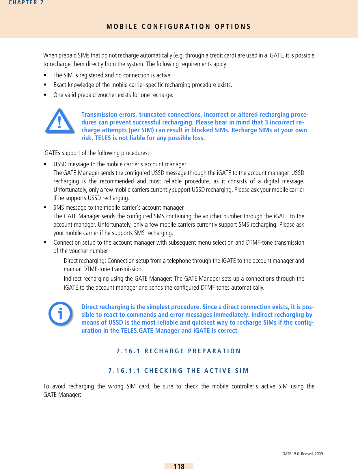
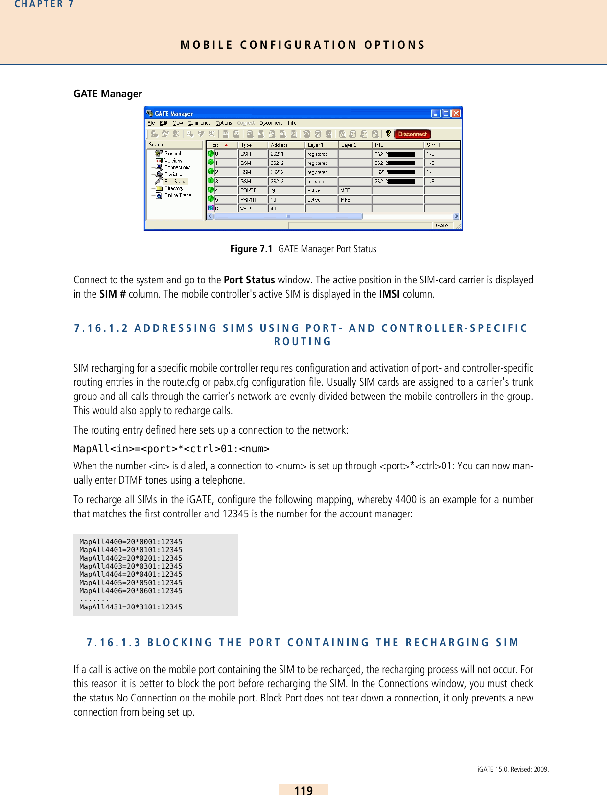
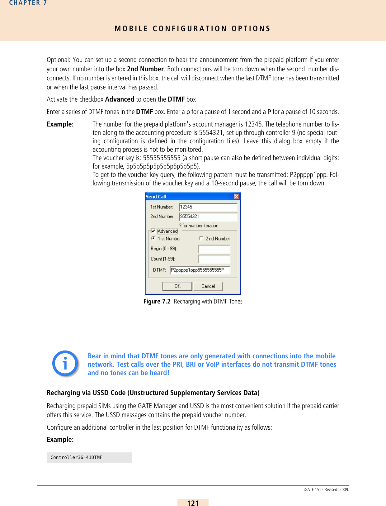
![MOBILE CONFIGURATION OPTIONSCHAPTER 7122iGATE 15.0. Revised: 2009.The corresponding Subscriber line will look like this:The configuration file route.cfg must contain the following entry in the [System] section:MapAllDTMF=<dtmf port>DTMFMapAll<place>??=<port>*??01:orMapAll<place>??=<LAIN>*??01:First a placeholder is defined, followed by ?? so that one mapping entry applies for the entire group of the carrier'smobile controllers. The right side of the mapping entry begins with the mobile port number or the port's LAIN.Example: In the following example, prepaid SIMs from 2 different carriers are used in the system. The lettersY and Z are used as placeholders, and the carrier's LAINs are 26212 and 26213 (based on theGerman country code):Subscriber36=TRANSPARENT ROUTER CHMAX[5]MapAllDTMF=41DTMFMapAllY??=26212*??01:MapAllZ??=26213*??01:](https://usermanual.wiki/Teles-Informationstechnologien/GSM32VOIPUS/User-Guide-1224551-Page-122.png)
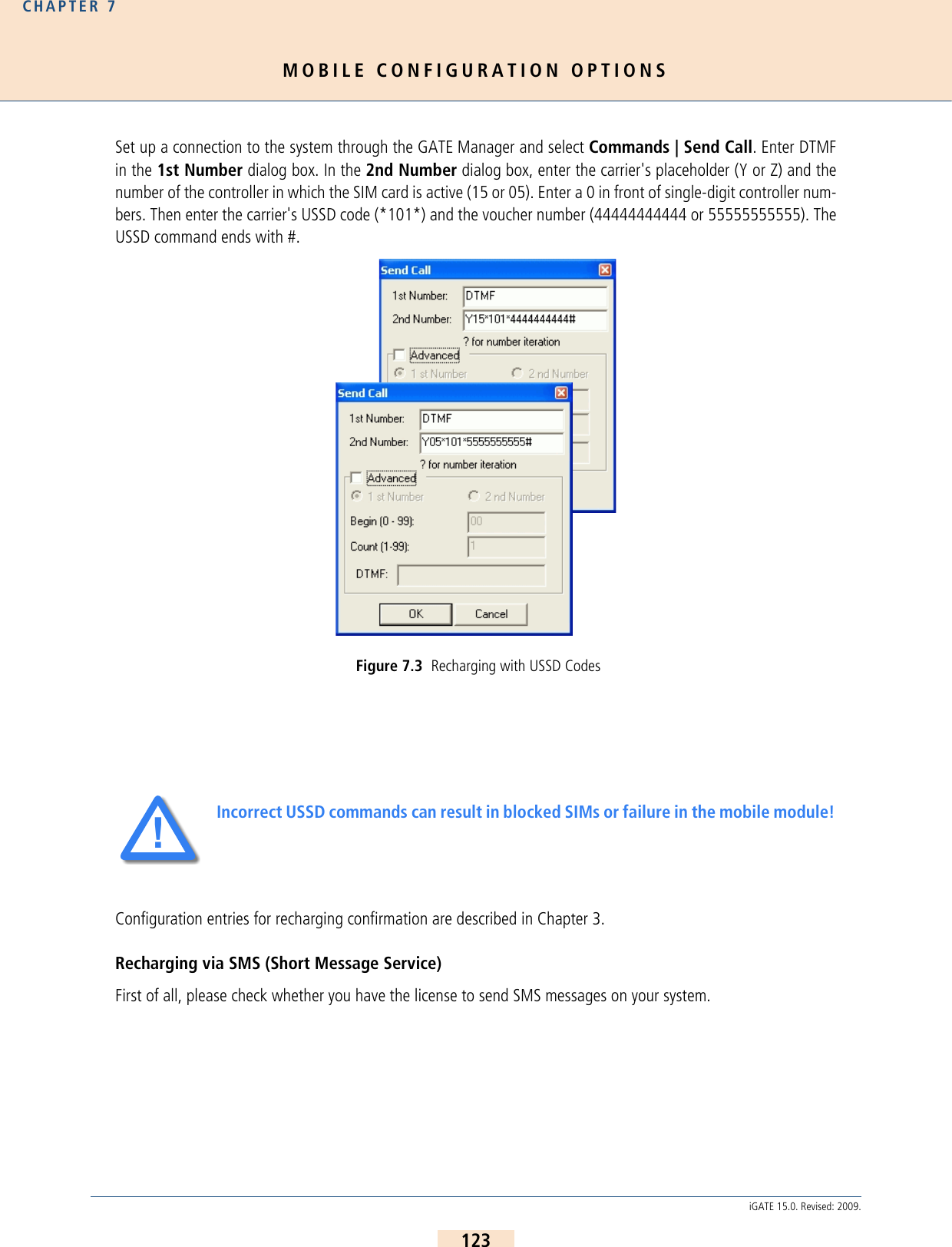
![MOBILE CONFIGURATION OPTIONSCHAPTER 7124iGATE 15.0. Revised: 2009.You will find it in the General view under Licenses when you connect to the system via GATE Manager.Figure 7.4 GATE Manager General ViewThe name for the license is SMS. This entry is required to send SMS.You must configure the mail service in the [Mail] section of the file pabx.cfg if you want to send the SMS messageswith an e-mail client through a mail server or directly to the iGATE:[Mail]SmtpServer=<server addr>MailRcpt=<domain>MailFrom=<own address or name>The third entry in the mobile controller's Subscriber line is the SMS center number: German example: You must restart the system to activate the changes.Then enter the port-specific SMS settings: MapAllSMS<shortnumber>=LAIN*0001:<number>MapAllSMS<shortnumber>=port*0001:<number>Example: In the following German example with LAIN numbers, the short number 00 is routed to the firstThis entry is not necessary when using only the GateManager's Send SMS command.Subscriber00=TRANSPARENT ROUTER GSM[0000,00000,+00000,1,1,1,SIMS,IMSI] CHADDR ALARMSubscriber00=TRANSPARENT ROUTER GSM[0000,00000,+491721111,1,1,1,SIMS,IMSI] CHADDR ALARMii](https://usermanual.wiki/Teles-Informationstechnologien/GSM32VOIPUS/User-Guide-1224551-Page-124.png)
![MOBILE CONFIGURATION OPTIONSCHAPTER 7125iGATE 15.0. Revised: 2009.controller. The number 12345 is sent to the SMS center.If the SMS is sent with a normal e-mail client, the keyword SMS will appear in the To dialog box, followed by theshort number, which indicates the mobile controller. An @ sign and the iGATE's IP address or name if the systemis attached to a DNS server will follow. The message box contains the recharge code in the carrier's syntax.SMS00@<ipaddr>SMS00@<domain>If the SMS is used with the Send SMS command in theGATE Manager's Commands menu, use only the short numberand not the keyword SMS.To save the recharge platform's confirmation e-mail, the e-mailcan be sent to an account using the following entry in theroute.cfg:Restrict<port>=@<addressee> 05It can also be saved into a file using the following entry in thepabx.cfg:MsgLog=/data/msg.logTo save it into a file, the following entry in the route.cfg is alsorequired:Restrict<port>=@FILE 05Example: In the following example for saving the SMS into a file, all incoming SMS to LAIN 26212 is savedinto the file msg.log:If the e-mail is sent to an account, the routing entry will look like this: Use the following entries in the pabx.cfg to connect the iGATE to an e-mail server:[Mail]SmtpServer=<server address>MailRcpt=<domain>MailFrom=<own address or name>MapAllSMS00=26212*0001:12345MapAllSMS01=26212*0101:12345MapAllSMS02=26212*0201:12345MapAllSMS03=26212*0301:12345MapAllSMS04=26212*0401:12345MapAllSMS05=26212*0501:12345MapAllSMS06=26212*0601:12345……Restrict26212=@FILE 05Restrict26212=@nase 05Figure 7.5 Send SMS](https://usermanual.wiki/Teles-Informationstechnologien/GSM32VOIPUS/User-Guide-1224551-Page-125.png)
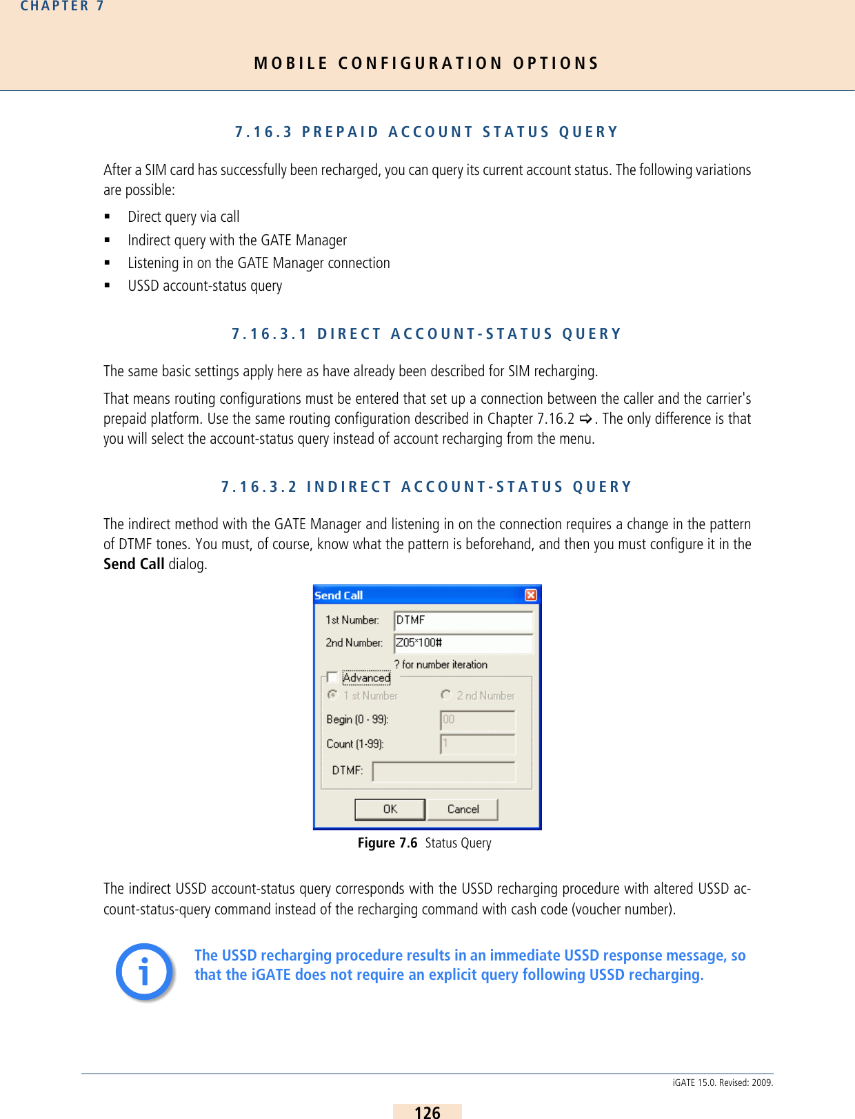
![MOBILE CONFIGURATION OPTIONSCHAPTER 7127iGATE 15.0. Revised: 2009.7.16.3.3 SAVING /FORWARDING THE ACCOUNT STATUSAccount-status information can be saved to a file in the iGATE. The following entry in the pabx.cfg is required:MsgLog=/data/msg.log The corresponding routing entries in the route.cfg configuration file will look like this:Restrict<port>=@FILE 06Restrict<LAIN>=@FILE 06Example: The following example shows incoming USSD messages for 2 carriers:The USSD entry in the file will appear in 2 lines as follows:Date Time [Port] IMSIUSSD Message TextExample:7.17 DEFINING SPECIAL CHARACTERS FOR VOICE CALLSIn cases in which the called number includes special characters (e.g. * or #), it may be necessary to define the calltype used in the mobile network (command or voice call). Calls to GSM or CDMA that begin with * or #, are sentas command calls by default. For voice calls beginning with * or #, you must define the call type voice in the map-ping entry with a > sign.The routing entry will look like this:MapAll<num>=<LAIN>><num>Example:Restrict26212=@FILE 06 Restrict26213=@FILE 0614.02.05-17:40:06 [04] 262125555555555 Current Cash Account: 143,83 EurosMapAll222=11111>*222](https://usermanual.wiki/Teles-Informationstechnologien/GSM32VOIPUS/User-Guide-1224551-Page-127.png)
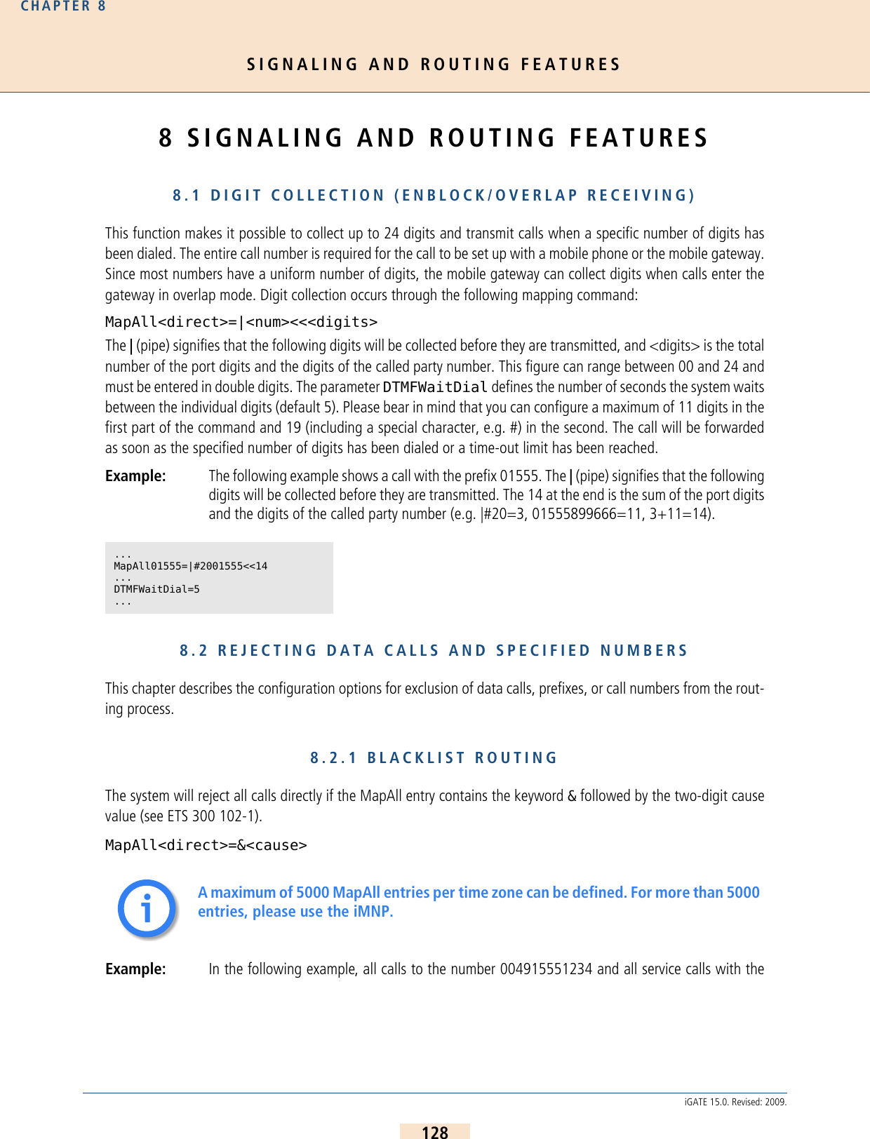
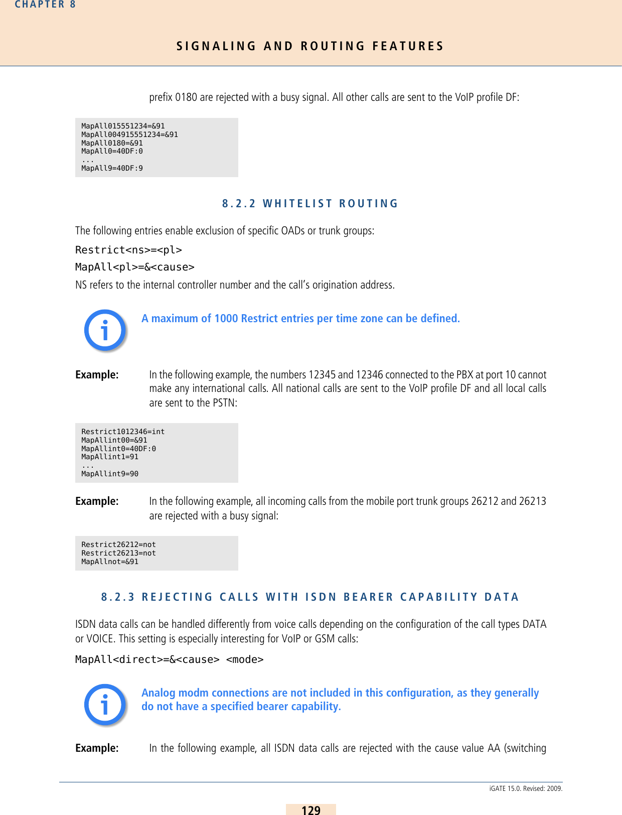
![SIGNALING AND ROUTING FEATURESCHAPTER 8130iGATE 15.0. Revised: 2009.equipment congestion). All calls with the prefix 0170 are routed to the mobile trunk group 26211and all other calls are routed through VoIP:8.2.4 SPECIFIC ROUTING OF DATA CALLS VIA VOIPIn the ISDN network, data calls have a special service type. When an ISDN PBX is connected to a VoIP network, itmust continue to work without any problems (e.g. PBX remote maintenance calls or ISDN terminal adapter). In thecase of VoIP, a specific RTP payload type is used: trp, ccd or gnx64.Example: In the following example, two VoIP profiles are configured, so that all calls are routed, regardlessof whether they are data calls or voice over IP calls. The first one is for outgoing voice calls andall calls from VoIP to ISDN. The second profile is exclusively for outgoing data calls, so that sig-naling consists solely of clear mode in SDP: 8.3 CLIP AND CLIR8.3.1 ROUTING CLIP AND CLIR CALLSThis function allows you to route calls with Calling Line Identification Presentation (CLIP) differently from calls withCalling Line Identification Restriction (CLIR). For example, all CLIP calls can be rejected, so that only calls that donot present the calling number or calls without a calling party number (e.g. analog) are transmitted through theiGATE.MapAll0=&aa DATA...MapAll9=&aa DATA... MapAll0170=262110170MapAll0=40DF:0...MapAll9=40DF:9MapAll0=40DATA:0 DATA...MapAll9=40DATA:9 DATAMapAll0=|40DF:0<<24...MapAll9=|40DF:9<<24Restrict40=InMapAllIn=10[Voip:DF]VoipDirection=IO...VoipCompression=g711a g729 trp t38...[Voip:DATA]VoipDirection=Out...VoipCompression=trpVoipECE=No...](https://usermanual.wiki/Teles-Informationstechnologien/GSM32VOIPUS/User-Guide-1224551-Page-130.png)
![SIGNALING AND ROUTING FEATURESCHAPTER 8131iGATE 15.0. Revised: 2009.Use the following configuration to define the various routing methods: InsertCLIR=On activates this mode. 01 is the service indicator for telephony (analog and ISDN) and is used to dif-ferentiate these calls from remote administration calls. Restrict9=OK 01 means that all telephony calls without acalling number are put through. Restrict|9=OK 01 means that all CLIR telephony calls are put through.Restrict90=FAIL 01 means that all CLIP telephony calls are rejected with No Channel Available as rejection causewhen they are mapped to MapInFAIL=&aa. 8.4 ROUTING CALLS WITHOUT CLIRThis function enables you to bypass CLIR for calls through the defined mobile port. The following configuration inpabx.cfg activates this function:8.4.1 SETTING CLIRSetting a hash (#) in front of a call number makes it possible to suppress the presentation of the origination numberof calls regardless of how the call comes into the system.The following sytax is used: MapAll<num>=#<port><num>Example: The following example shows an appropriate configuration. With this entry, all calls beginningwith 00491555 are sent to the port with the address 22 and the presentation of the number isrestricted:8.4.2 SETTING CLIPSetting an exclamation point (!) in front of a call number makes it possible to force the presentation of the origi-nation number of calls regardless of how the call comes into the system....InsertCLIR=On...Restrict9=OK 01Restrict|9=OK 01Restrict90=FAIL 01...MapInOK00491555=2200491555MapInFAIL=&aa...Subscriber<xx>=...GSM[...,!CLIR]...When this function is configured, the SIM’s telephone number (and not originating telephone) is always transmitted to the B subscriber.MapAll00491555=#2200491555ii](https://usermanual.wiki/Teles-Informationstechnologien/GSM32VOIPUS/User-Guide-1224551-Page-131.png)
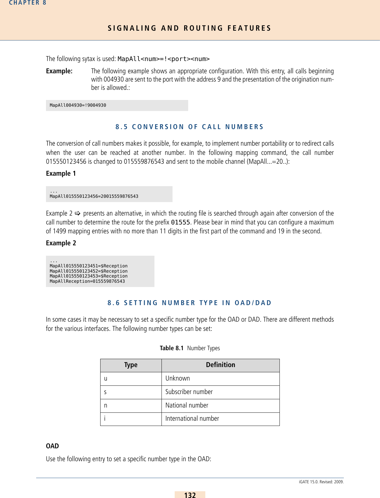
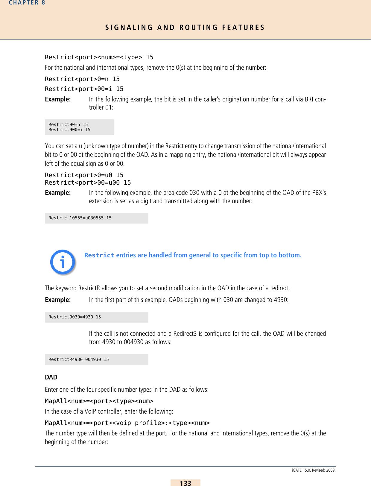
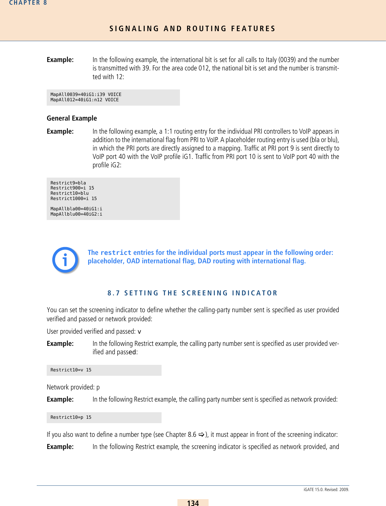
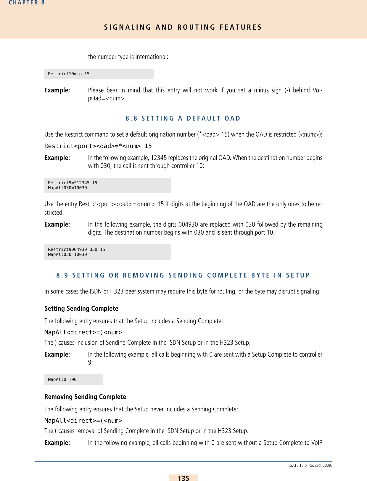
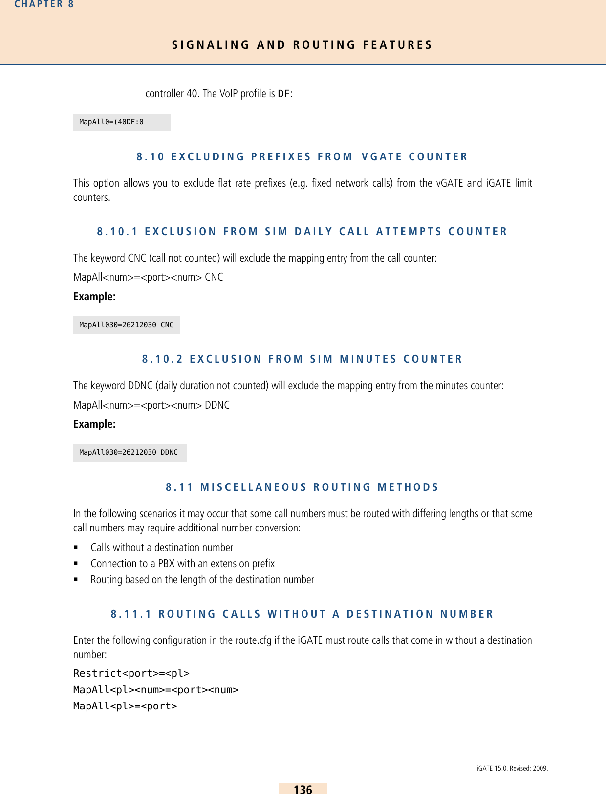
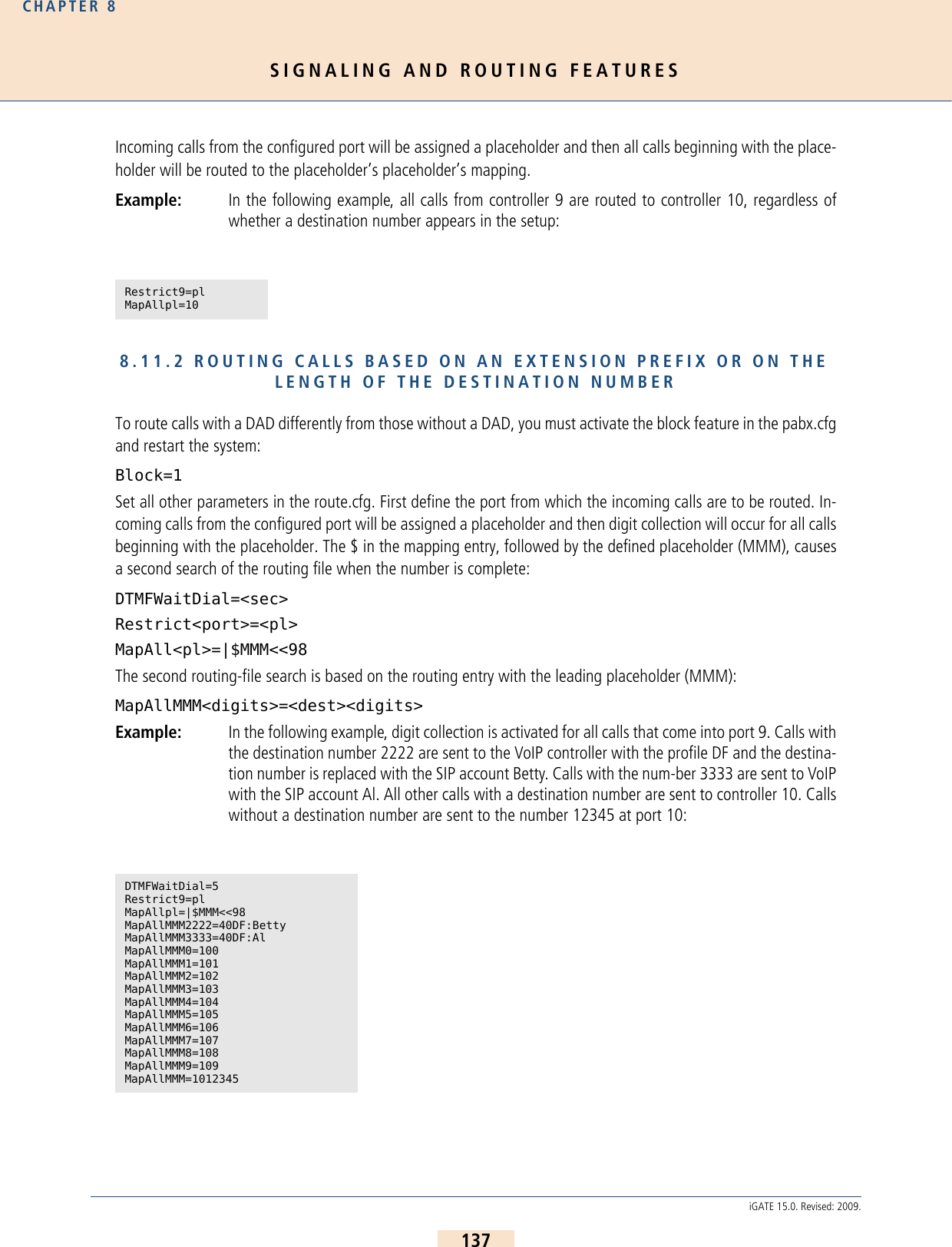
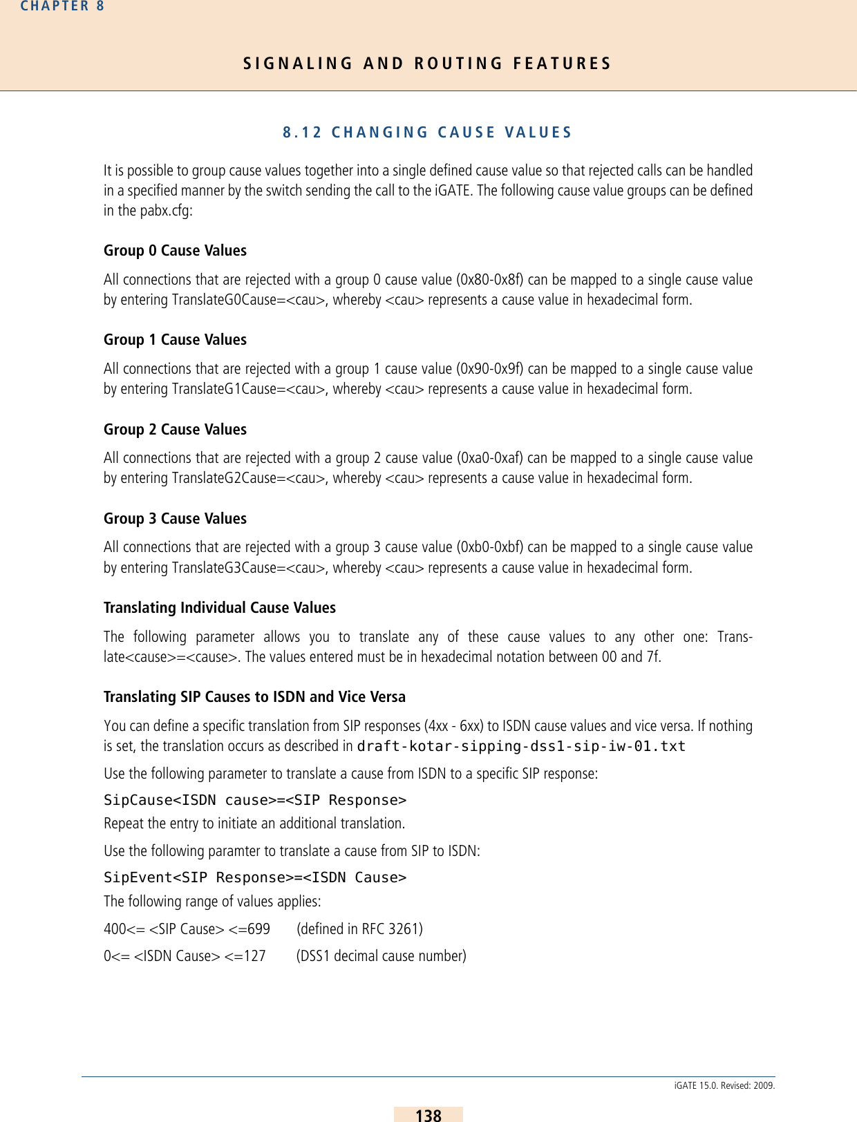
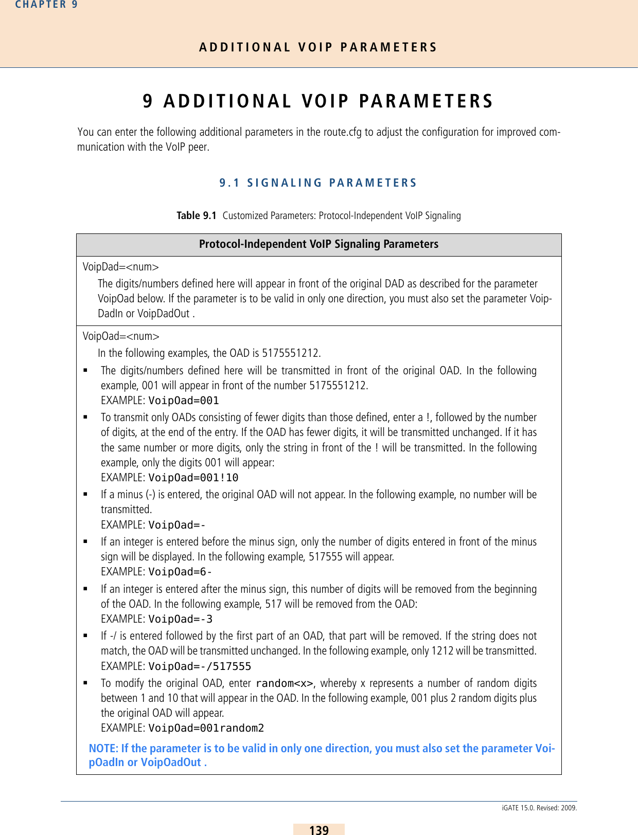
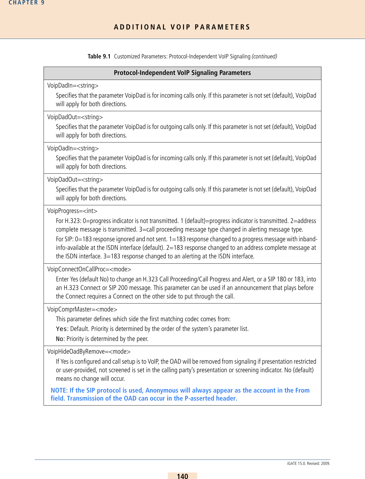
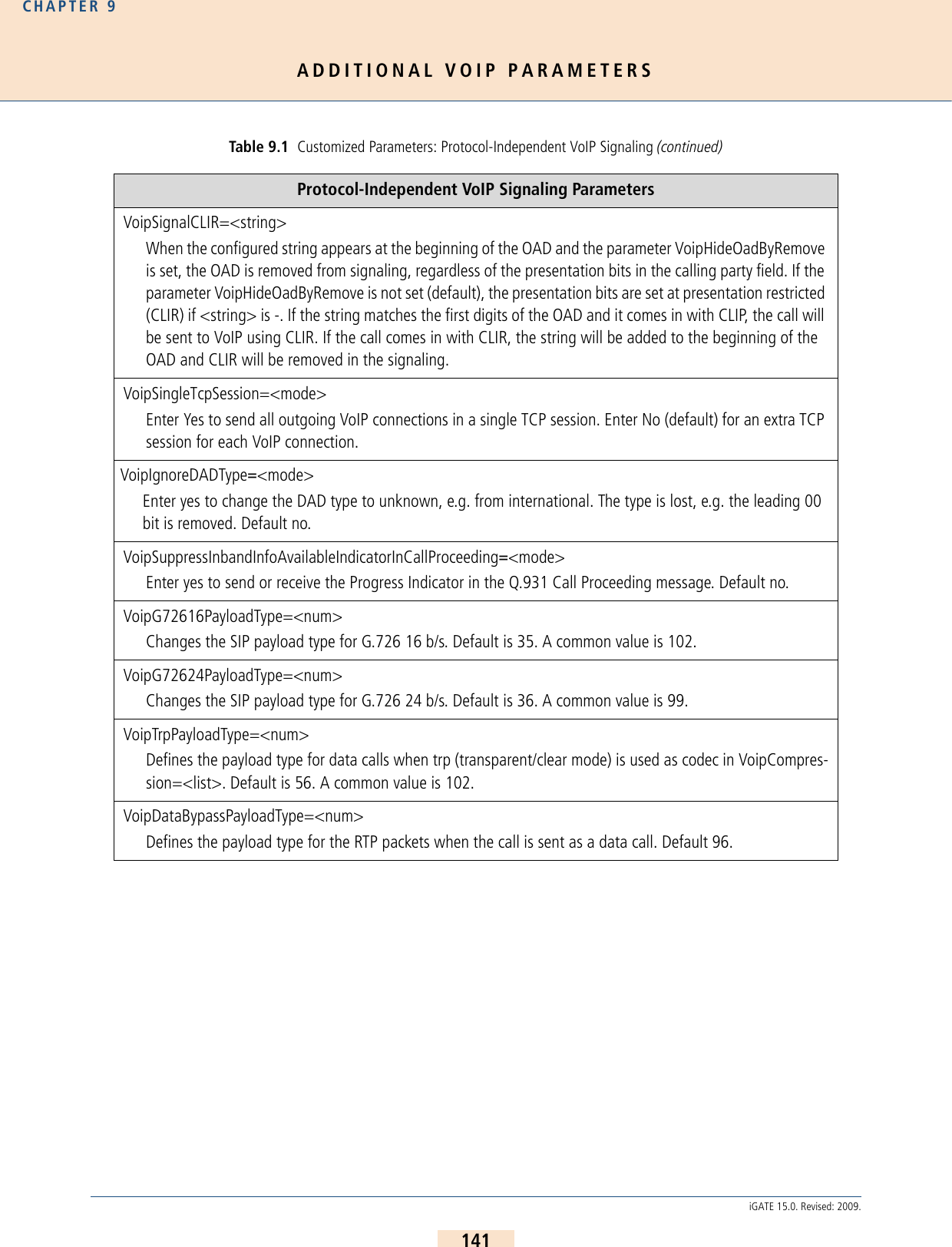
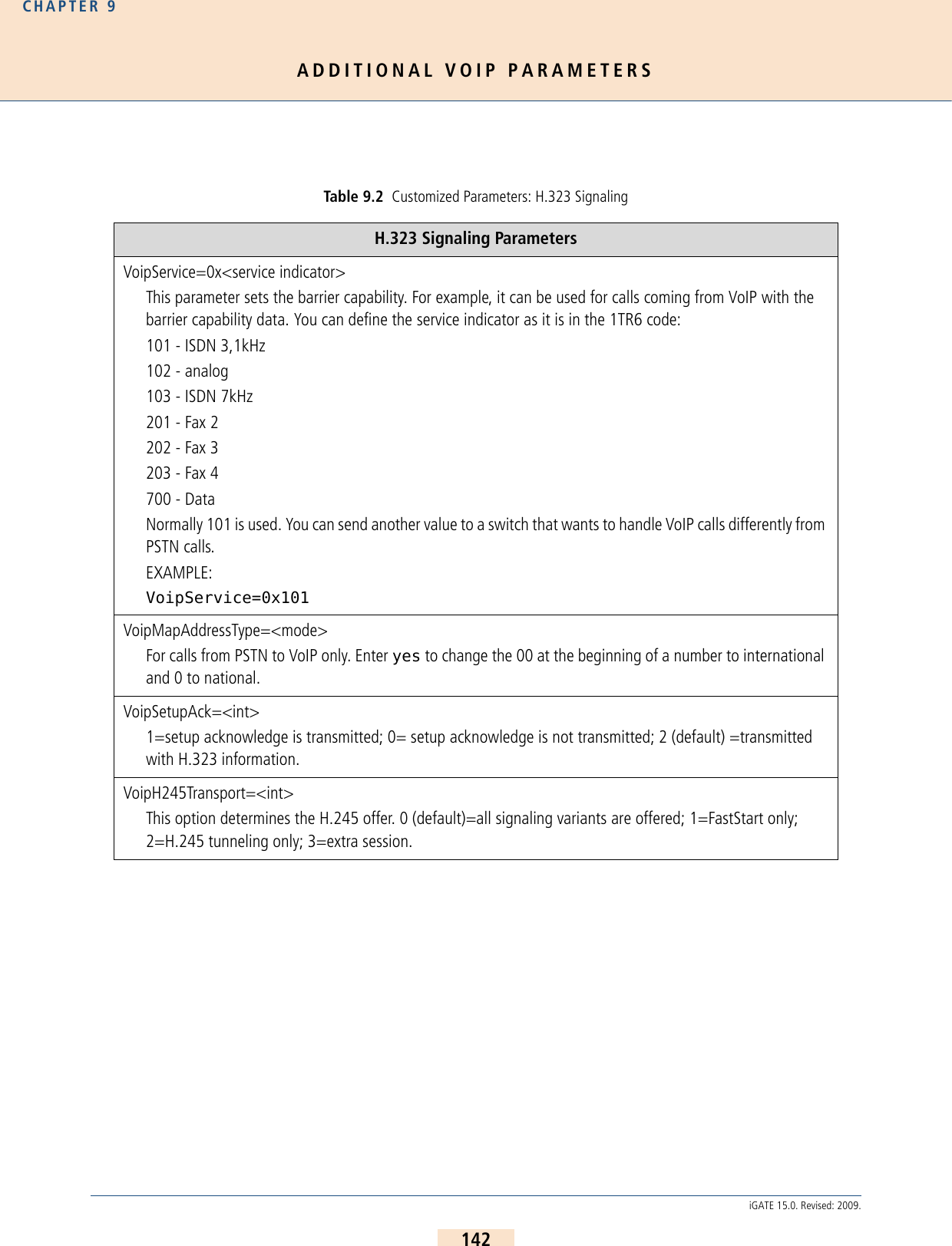
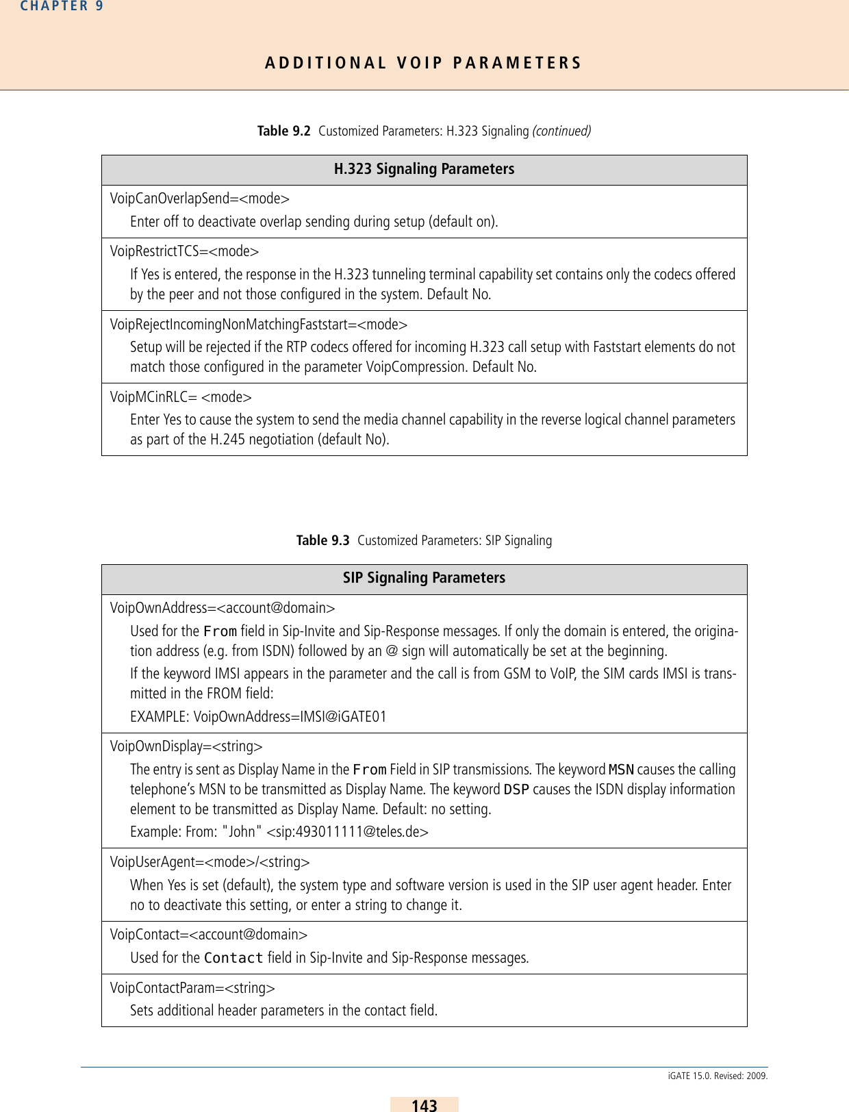
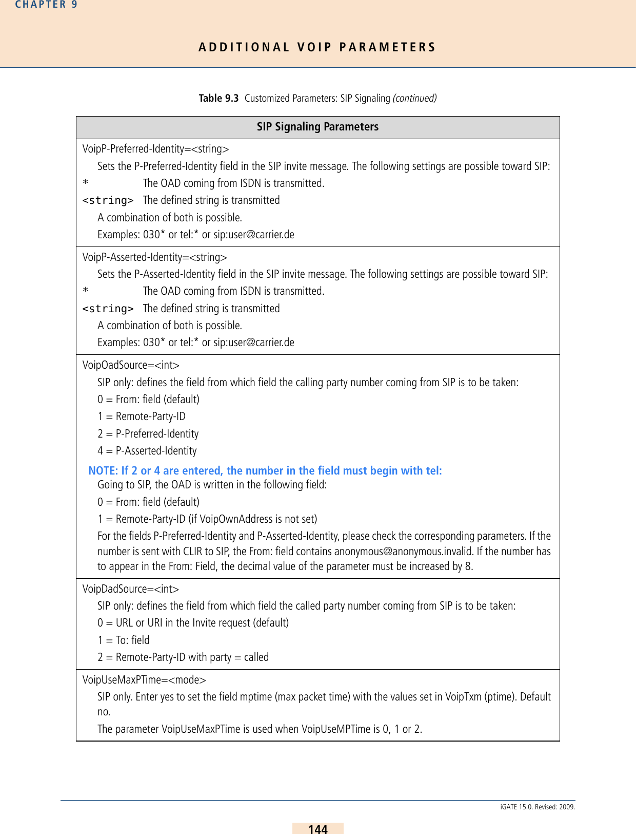
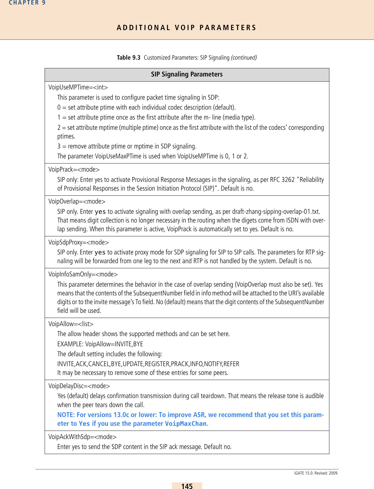
![ADDITIONAL VOIP PARAMETERSCHAPTER 9146iGATE 15.0. Revised: 2009.9.2 REGISTRAR PARAMETERSThe following parameters can be used in the VoIP profile when the SIP agent wants to register with the iGATE. Example: The following example creates an account for a user agent with the username 130 and passwordtest130. Authentication occurs with the procedure www:Table 9.4 Customized Parameters: Location Server Location Server ParametersVoipOwnUser=<string>Defines the username the agent uses to register.VoipOwnPwd=<string>Defines the password the agent uses to register.VoipExpires=<sec>Defines the maximum number of seconds the agent’s registration applies (default 3600).VoipAuth=<mode>Defines the authentication procedure www (default) or proxy.MapAll130=40U1:130[Voip:U1]VoipDirection=IOVoipIpMask=0x00000000VoipOwnUser=130VoipOwnPwd=test130VoipExpires=300VoipAuth=wwwVoipCompression=g711a g711u g729 g729a g729b g729ab VoipSilenceSuppression=noVoipSignalling=1VoipMaxChan=8VoipTxM=2VoipDtmfTransport=0VoipRFC2833PayloadType=101VoipMediaWaitForConnect=Tone](https://usermanual.wiki/Teles-Informationstechnologien/GSM32VOIPUS/User-Guide-1224551-Page-146.png)
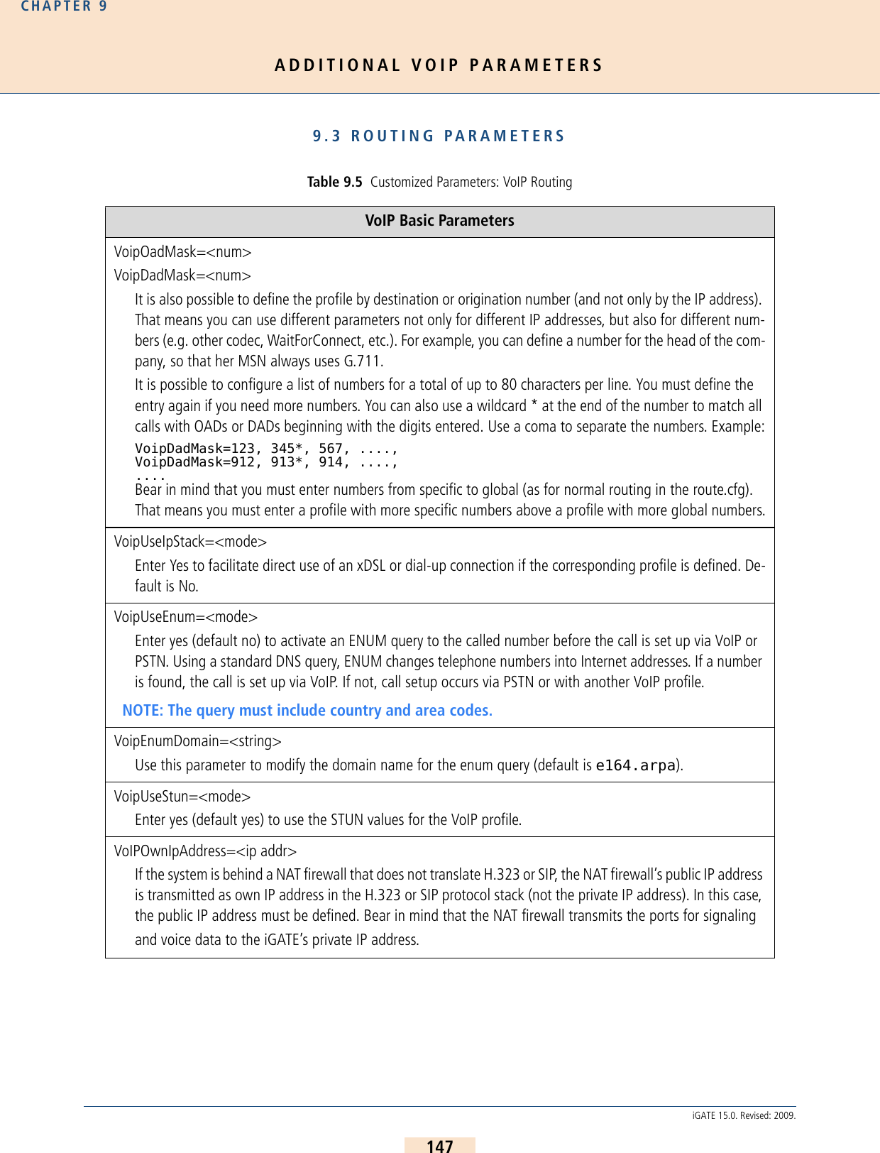
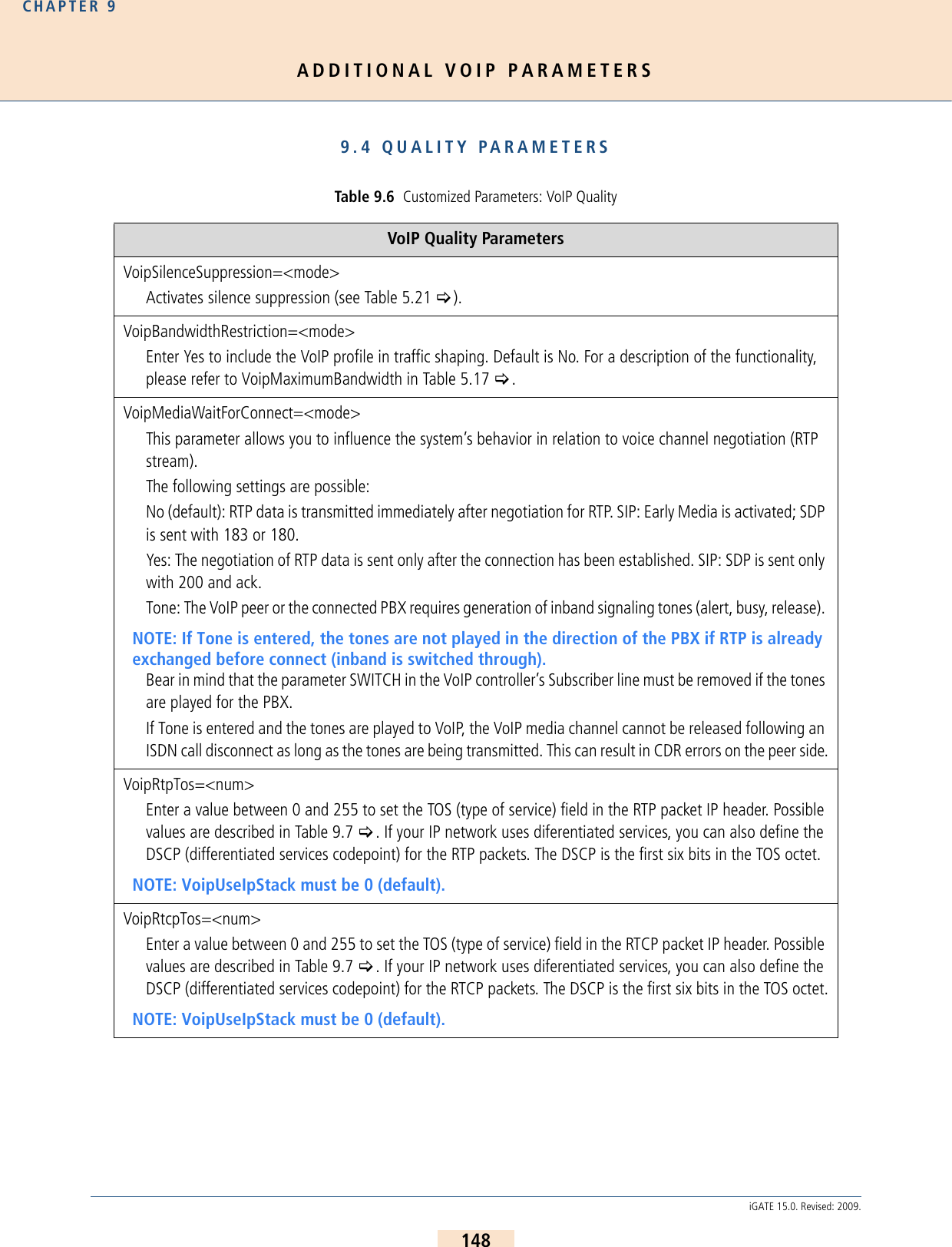
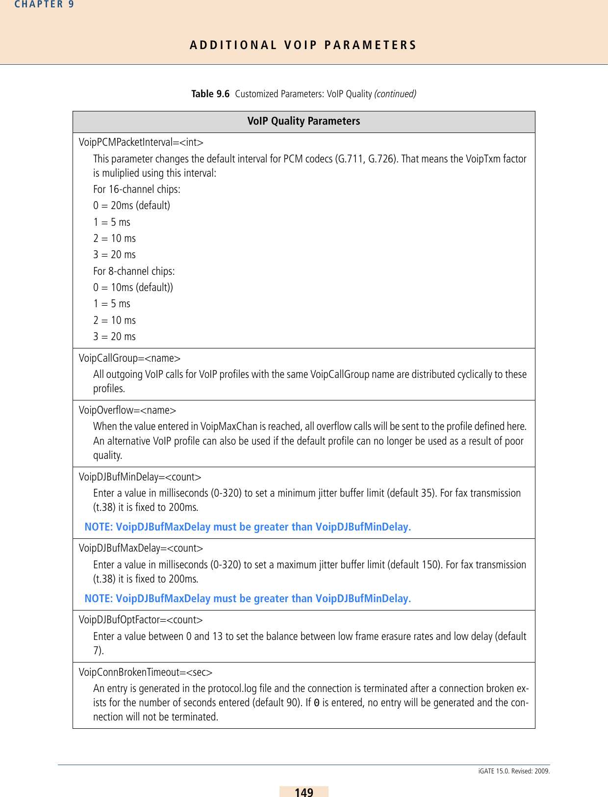
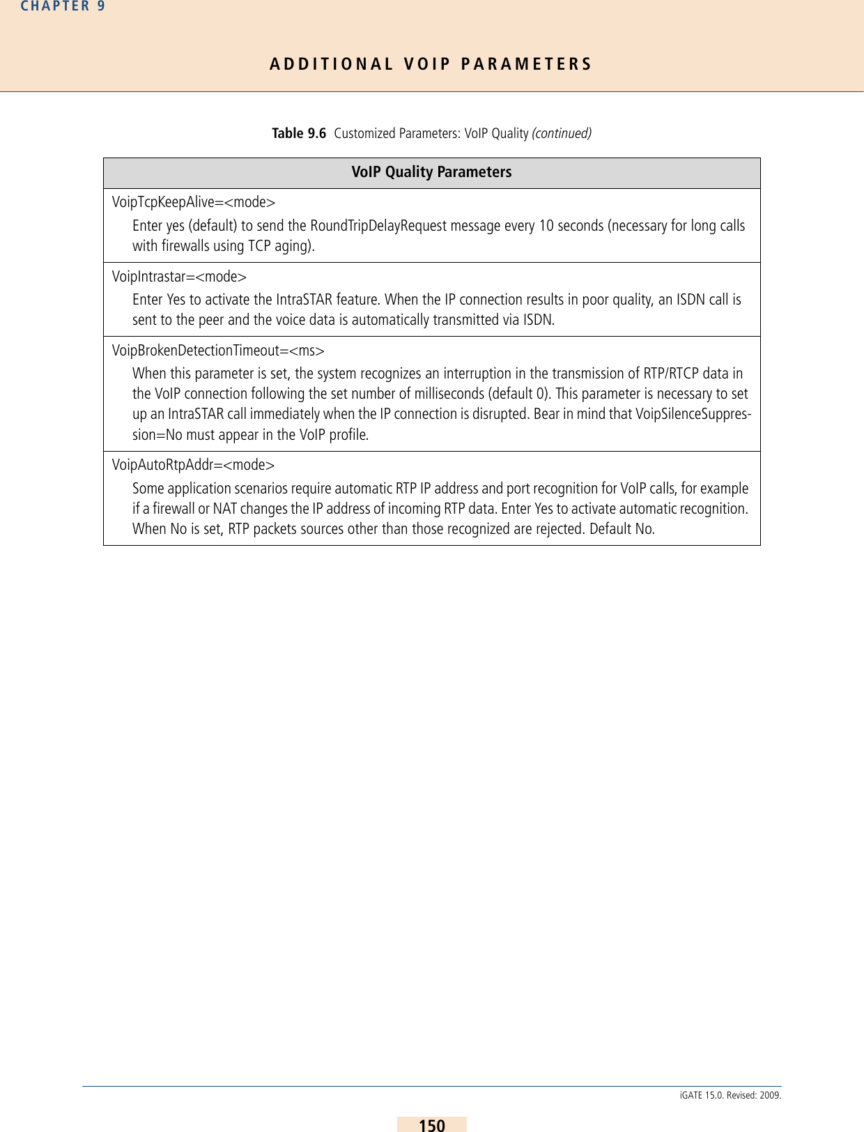
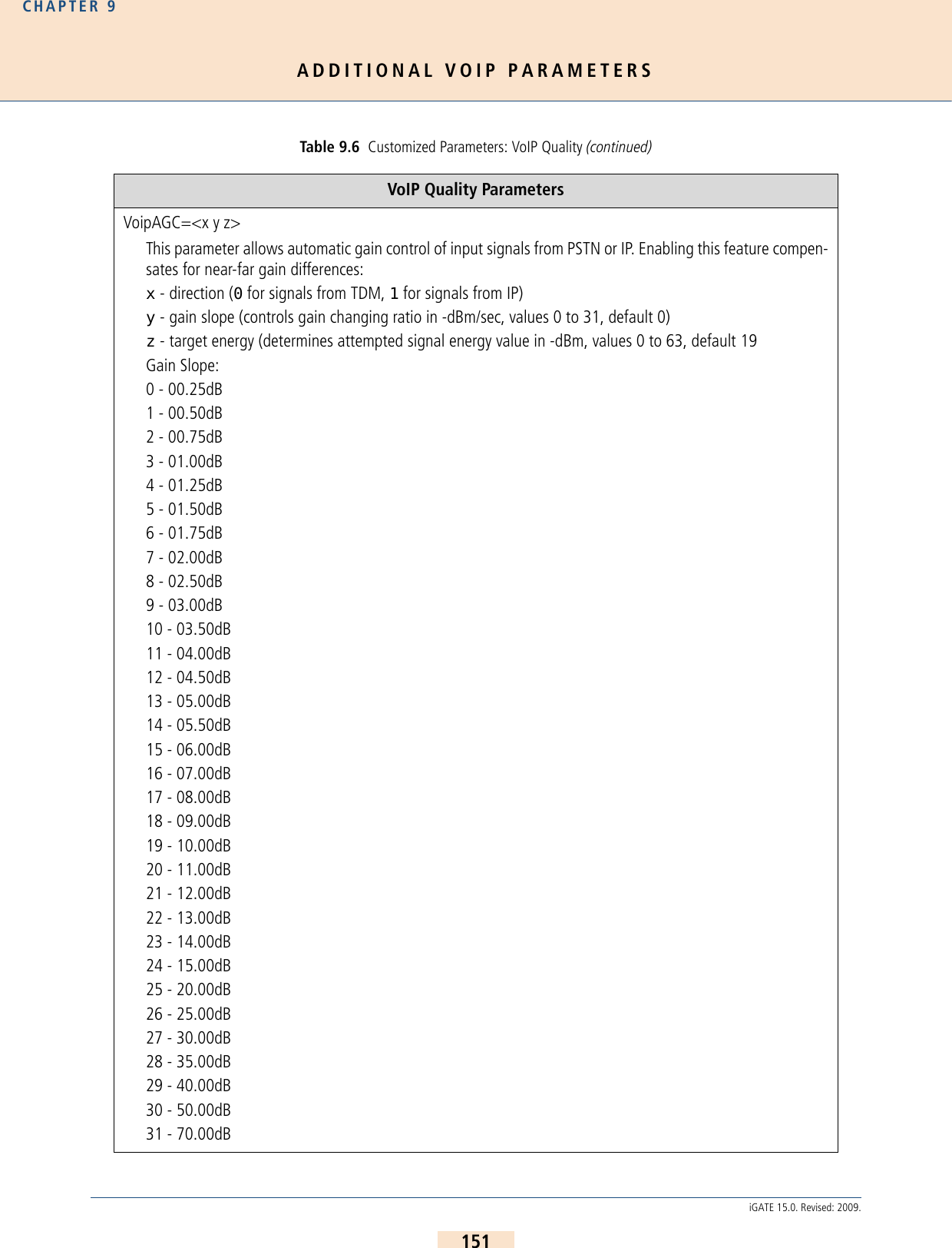
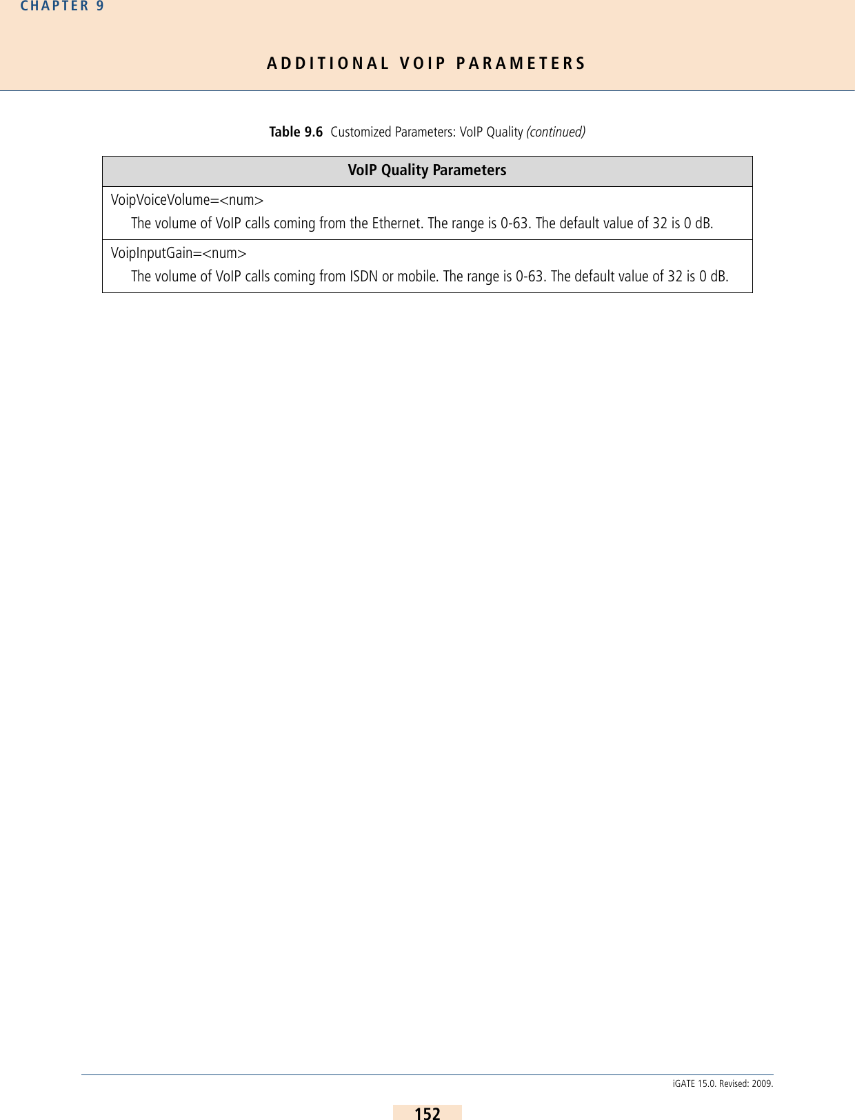
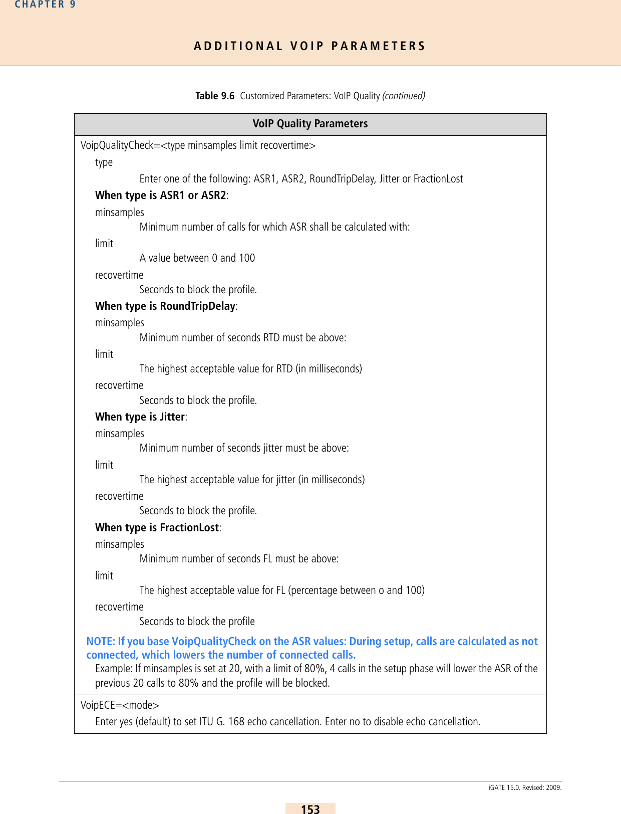
![ADDITIONAL VOIP PARAMETERSCHAPTER 9154iGATE 15.0. Revised: 2009.The following specifications for Quality of Service correspond with RFC791 and RFC1349.VoipEcl=<ms>This parameter defines the required tail length for echo cancelation. The following values in ms are possible:3264 (default)128VoipT301=<sec>An outgoing VoIP calls will be canceled in the state of Alerting (for H323) or Ringing (for SIP) if the number of seconds entered has passed and there is no response from the IP or VoIP carrier.VoipT303=<sec>If this parameter is entered in a SIP profile, transmission of the INVITE is canceled after the number of seconds entered has passed. The call can then be redirected, for example to PSTN. This improves the reliability of the system when an IP or VoIP carrier’s service fails.EXAMPLE:Redirect340DF:=AMapAllA=9[Voip:DF].....VoipT303=5VoipT304=<sec>An outgoing VoIP calls will be canceled in the state of Setup Acknowledge (for H323) or Trying (for SIP) if the number of seconds entered has passed and there is no response from the IP or VoIP carrier.VoipT310=<sec>An outgoing VoIP calls will be canceled in the state of Call Proceeding (for H323) or Session Progress (for SIP) if the number of seconds entered has passed and there is no response from the IP or VoIP carrier.Table 9.7 Quality of Service Values Bit Distribution01234567Precedence TOS MBZBit Description0-2 Precedence3 TOS: 0=normal delay, 1=low delay4 TOS: 0=normal throughput, 1=high throughput5 TOS: 0=normal reliability, 1=high reliabilityTable 9.6 Customized Parameters: VoIP Quality (continued)VoIP Quality Parameters](https://usermanual.wiki/Teles-Informationstechnologien/GSM32VOIPUS/User-Guide-1224551-Page-154.png)
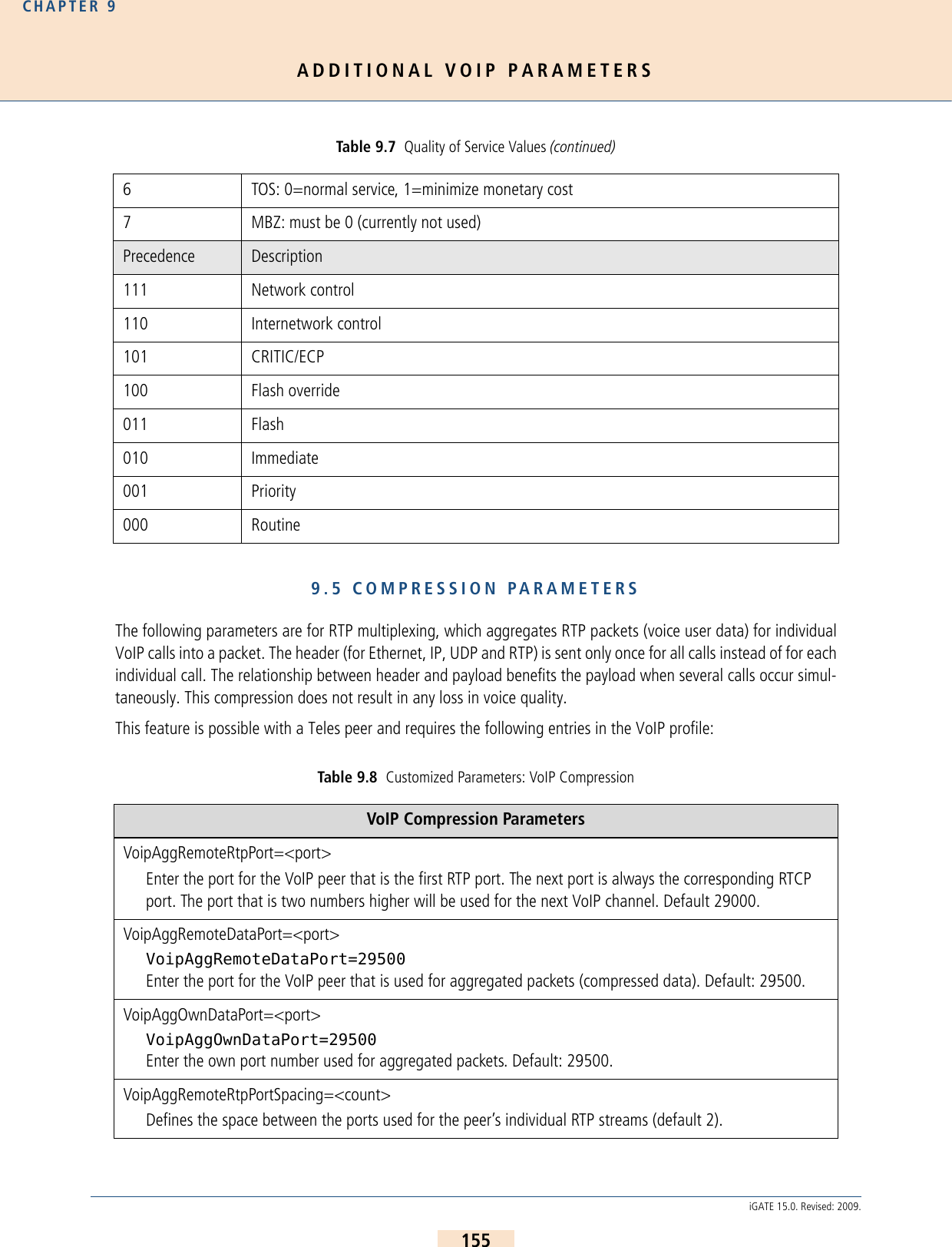
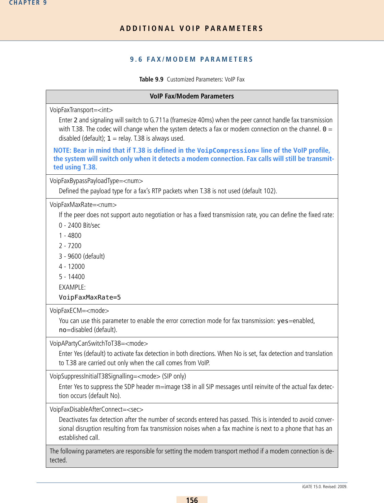
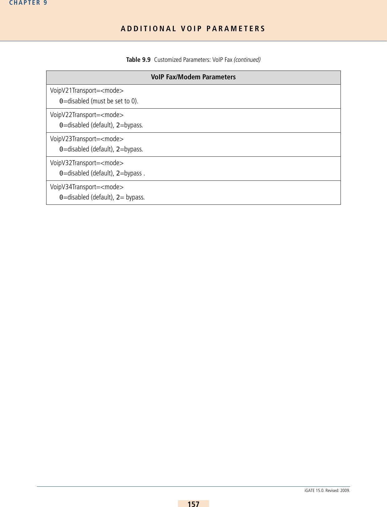
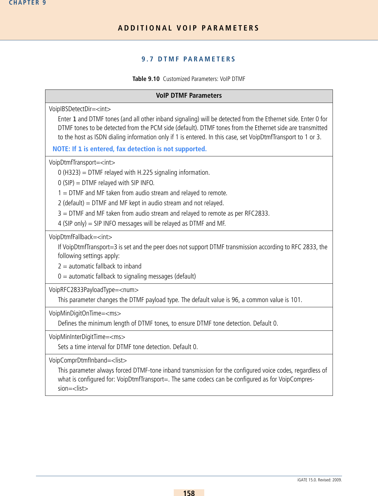
![SYSTEM MAINTENANCE AND SOFTWARE UPDATECHAPTER 10159iGATE 15.0. Revised: 2009.10 SYSTEM MAINTENANCE AND SOFTWARE UPDATE10.1 CONFIGURATION ERRORSWhen typographical errors are made in the configuration files, an entry appears in the protocol.log when theconfiguration is activated. This entry includes the line number and its contents.10.2 STATUS AND ERROR MESSAGESThe protocol.log file – assigned as the file for logging the protocol in the configuration file(ActionLog=file) – contains information on all activities within the system. In the example below, you can seethat all activities are recorded beginning with the date and time. If functions were activated by key combinationsfrom terminal devices you can identify these along with the service ID.16.05.06-11:51:31,[990]Start STATUS - TELES.iGATE V11.7a (007f)16.05.06-12:10:57,[01A]ERR: Layer1 16.05.06-12:10:58,[000]ERR: OK 16.05.06-12:10:58,[010]ERR: OK 16.05.06-12:12:06,Remote Control from IP 192.168.1.216.05.06-12:12:06,Remote Control: OK 16.05.06-12:12:16,Activate Configuration System 16.05.06-12:16:26,Remote Control Terminated 16.05.06-14:00:00,Activate Configuration Night2 16.05.06-14:00:00,Time Switch Operation 16.05.06-18:00:00,Activate Configuration Night3 16.05.06-18:00:00,Time Switch Operation Table 10.1 Event Log Messages Message NMS DefinitionStatus Program[990] Start STATUS X TELES system software and status program have been started. System Start[999] System-Boot X System restarted by timer.[999] Remote Control: Reboot System restarted by remote administration command.Configuration ChangesActivate configuration <num> OKConfiguration <num> successfully loaded. Initiator displayed in next line.Activate configuration <num> failed [<err>]Configuration <num> could not be loaded.](https://usermanual.wiki/Teles-Informationstechnologien/GSM32VOIPUS/User-Guide-1224551-Page-159.png)
![SYSTEM MAINTENANCE AND SOFTWARE UPDATECHAPTER 10160iGATE 15.0. Revised: 2009.Remote Control: Date & Time changedDate and/or time were changed via remote administration.Time Switch Operation The configuration change was made by the timer.Remote AdministrationRemote Control from <peer>, <RemoteCode>, <service>, 0Remote administration access from number or IP address.Remote Control: OK Successful remote administration access.[993]Remote Control: wrong passwordX Remote administration access was denied because of a wrong pass-word.[994]Remote Control: wrong numberX Remote administration access was denied because the call originat-ed from an unauthorized number (RemoteOrigination). Remote Control Terminated <start time>,<end time>, <num>, <RemoteCode>, <service>, 0Remote administration session from <num> ended. Session length is indicated by start time and end time.Errors Reported by the Status ProgramTable 10.1 Event Log Messages (continued)Message NMS Definition](https://usermanual.wiki/Teles-Informationstechnologien/GSM32VOIPUS/User-Guide-1224551-Page-160.png)
![SYSTEM MAINTENANCE AND SOFTWARE UPDATECHAPTER 10161iGATE 15.0. Revised: 2009.The following options are available for monitoring the iGATE 4 Mobile Boards’ status or the status of each mobilechannel. You can access status information through data recorded in the protocol.log file or in the Layer 1column in the GATE Manager’s Port Status window.[<port><i>] ERR: Problem at Port <num>X A Layer 1 or Layer 2 error occurred on <num>.<i> indicates error type:A Layer 1 error ; Layer 2 error 0 Layer 1&2 operational.4 RSSI (for mobile only)If the error persists, a differentiation is possible through 'status of the ports'.If this message appears, status inquiry connections via remote ad-ministration are accepted and NMS downloads the protocol.log file.NOTE: If the RSSI falls below the value configured in the pabx.cfg, the port will shut down automatically.Attention: No Callback-Call <num> ArrivedCallback with DTMF: the Callback Provider <num> did not call back within approx. 20 sec.Direct Line Access with DTMF: the call was accepted but disconnect-ed again within x sec. (as defined by MapCallBack-WaitDisc).Write error Access to the disk drive on which the data is to be stored was not possible because it is set for read-only, full or because of faulty hard-ware or software.[995] Msg-Memory > 75% X This message appears when message memory is over 75% full.If this message appears, status inquiry connections via remote ad-ministration are accepted and NMS downloads the protocol.log file.Table 10.1 Event Log Messages (continued)Message NMS Definition](https://usermanual.wiki/Teles-Informationstechnologien/GSM32VOIPUS/User-Guide-1224551-Page-161.png)
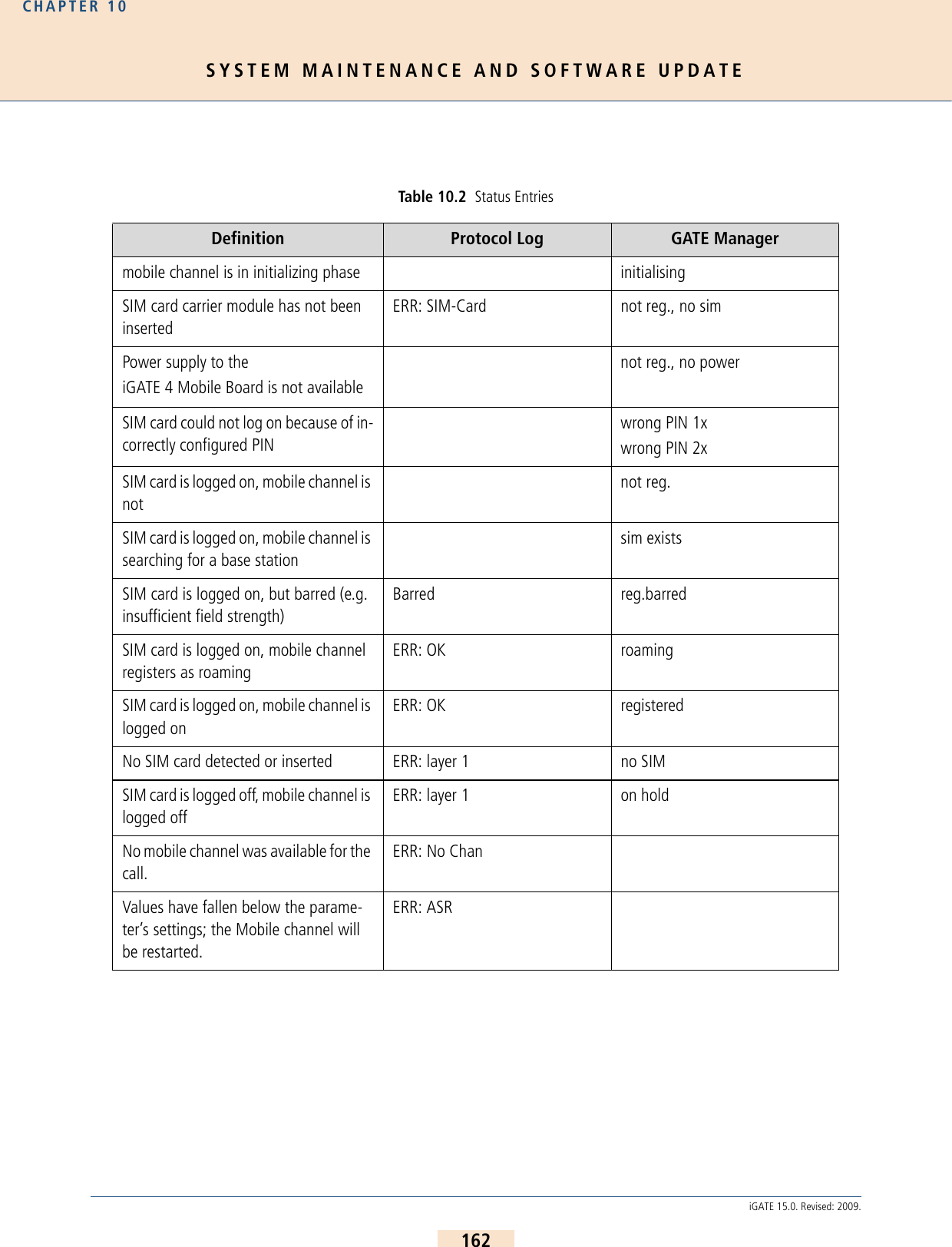
![SYSTEM MAINTENANCE AND SOFTWARE UPDATECHAPTER 10163iGATE 15.0. Revised: 2009.The following status and error messages appear in the protocol.log file when ALARM appears in the VoIPport’s subscriber line: Table 10.3 Protocol Log Status and Error Messages Message DefinitionSystem Configuration (a)config: <num> duplicate profile Specified line in pabx.cfg or route.cfg contains duplicate profile.config: <num> invalid Specified line in pabx.cfg or route.cfg is invalid.config: evaluation errcode <num> Internal error.Port-Specific Entries[<port>]Unblock Port The <port> has been unblocked. This can occur via remote access for all controller types or automatically via vGATE for mobile chan-nels.[<port>]Block Port The <port> has been blocked. This can occur via remote access for all controller types or automatically via vGATE for mobile channels.[<port>]Restart Port The <port> has been blocked. This can occur via remote access for all controller types or automatically via vGATE for mobile channels. Ethernet Interface[99d]ERR: emac<num><state> The Ethernet controller’s status is checked every minute and any change in status is noted.<num> Number of the EMAC interface (0 or 1).<state> up Ethernet link is activedown Ethernet link is inactive!resolve ip-address ARP request for specified IP address failed.pingcheck failed Ping to configured server failed for configured amount of time; host might reboot this port.Voice Packetizer Task (b)[<port>]ERR: OK, <count> devices The number (<count>) of DSPs were loaded during startup without errors. The first VoIP controller appears in [<port>].[<port>]ERR: init failed A DSP could not be loaded. This DSP or the first VoIP controller is defined in [<port>].VP: <channel> <msg> Voice-packetizer chips report fatal error on specified channel, with specified message.VoIP (c)GK <name> URC Successful UnRegister from specified gatekeeper.](https://usermanual.wiki/Teles-Informationstechnologien/GSM32VOIPUS/User-Guide-1224551-Page-163.png)
![SYSTEM MAINTENANCE AND SOFTWARE UPDATECHAPTER 10164iGATE 15.0. Revised: 2009.GK <name> GRJ <num> GatekeeperRequest was rejectedGK <name> RCF Successful RegistrationRequest (RegistrationConfirm).GK <name> RRJ <num> RegistrationRequest was rejected.GK <name> ARJ <dad> <num> AdmissionRequest was rejected.GK <name> !ACF dad AdmissionRequest was not answered.GK <name> !GCF GatekeeperRequest was not answered.no profile for ipaddress Incoming VoIP call from specified IP address was rejected due to no matching VoIP profile.registrar <name>: registration done Successful registration at SIP registrar.registrar <name>: wrong auth-type <num>Registrar does not perform MD5 for authentication.registrar <name>: gives no nonce Nonce missing in response from registrar (possible error in registrar configuration).registrar <name>: registration forbidden Registration with specified registrar is not allowed.registrar <name> not answering Specified registrar does not respond.voipconn oad->dad broken Voice codec chips report broken RTP connection.voip FdInitAll failed <cause> Internal failure.voip ISDNListen failed Internal failure.voipIpSocketInit failed Internal failure.!DNS-lookup <hostname> DNS lookup for specified host name failed (DNS not activated? Miss-ing or invalid DNS server?).message from <ip addr> not decodable H323, ASN1 packet cannot be decoded.vGATE[99]ERR: SimUnit !connect An outgoing connection to the vGATE Sim Unit could not be estab-lished. [99]ERR: ControlUnit <ip addr> !connect An outgoing connection to the vGATE Control Unit could not be es-tablished. Number Portability[99i]ERR: np !connect Connection to the iMNP could not be established. [99i]ERR: np connect <ip addr> Connection to the iMNP reestablished. Table 10.3 Protocol Log Status and Error Messages (continued)Message Definition](https://usermanual.wiki/Teles-Informationstechnologien/GSM32VOIPUS/User-Guide-1224551-Page-164.png)
![SYSTEM MAINTENANCE AND SOFTWARE UPDATECHAPTER 10165iGATE 15.0. Revised: 2009.System Kernel (e)task <name> suspended specified task was suspended due to internal error; host might re-boot this port.Mail (f)cdr !connect <ip addr> sending CDR: TCP connect to specified IP address failed.mail !connect <ip addr> sending e-mail: TCP connect to specified IP address failed.Radius (g)!DNS-lookup <hostname> DNS lookup for specified host name failed (DNS not activated? Miss-ing or invalid DNS server?).timeout auth <ip addr> Authentication request to specified Radius server failed due to tim-eout.timeout acnt <ip addr> Accounting request to specified Radius server failed due to timeout.!rsp-auth <ip addr> Response authenticator from specified Radius server was invalid (wrong secret/password?).!auth <ip addr> <num> Authentication denied by specified Radius server.Configuration Errors in the ip.cfgError in ip.cfg line <line>: section [<section_name>] unknownError in ip.cfg line <line>: parameter "<parameter_name>" in [<section_name>] unknownError in ip.cfg line <line>: parameter "<parameter_name>" does not belong to any SectionThere is an error in the NAT ConfigurationThe NAT was not loaded, please check the Configuration for mistakesThere is an error in the DHCPD ConfigurationThe DHCP SERVER was not loaded, please check the Configuration for mistakesThere is an error in the ALTQD ConfigurationThe ALTQD SERVER was not loaded, please check the Configuration for mistakesThere is an error in the FIREWALL ConfigurationThe FIREWALL was not loaded, please check the Configuration for mistakesError in <dsl_interface> Connection failed. Please, connect a cable in the <ethernet> portError in <dsl_interface>: Connection Failed. Please, revise your Username/Password configurationError in <dsl_interface>: Connection Failed. Please, revise the DSL ModemTable 10.3 Protocol Log Status and Error Messages (continued)Message Definition](https://usermanual.wiki/Teles-Informationstechnologien/GSM32VOIPUS/User-Guide-1224551-Page-165.png)
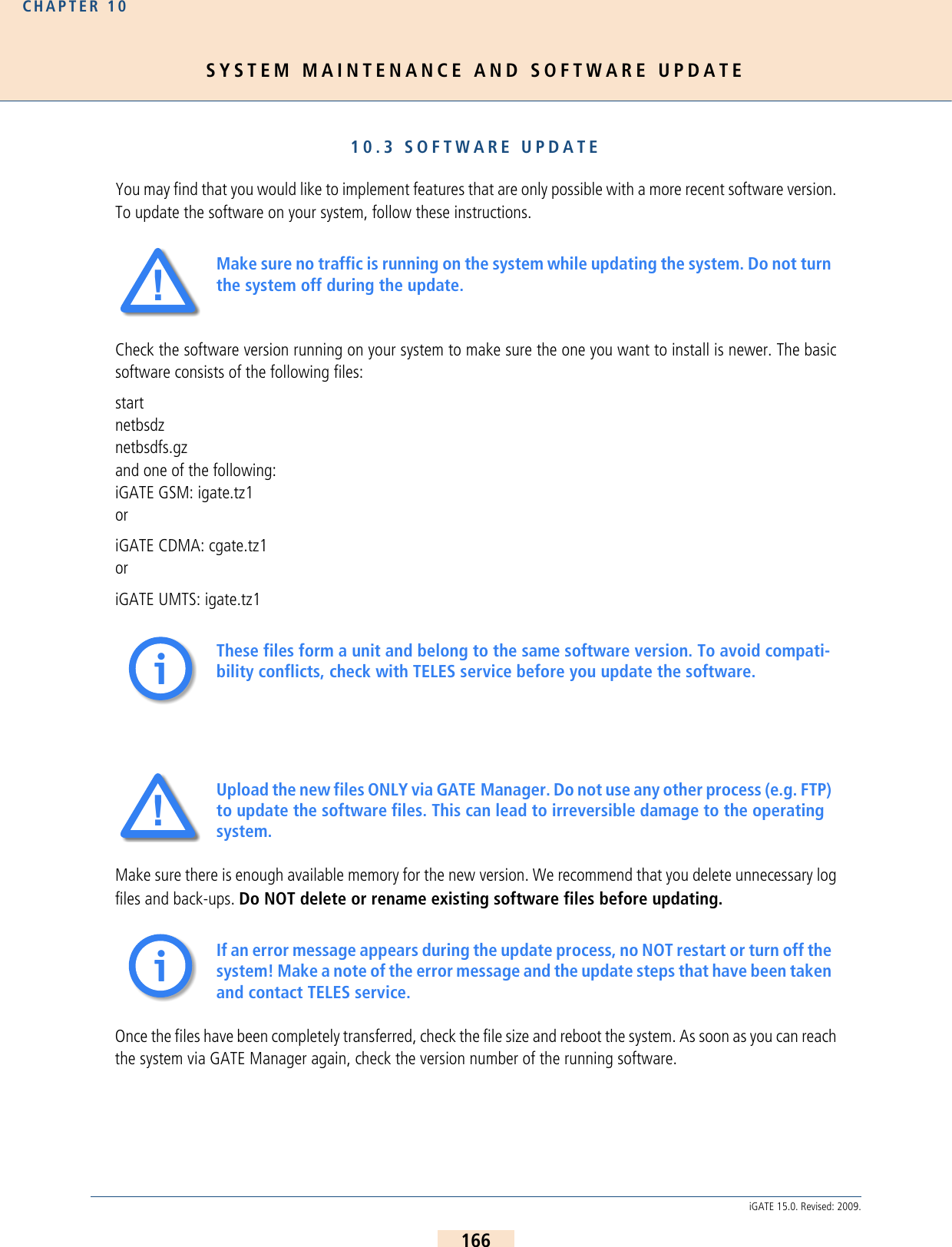
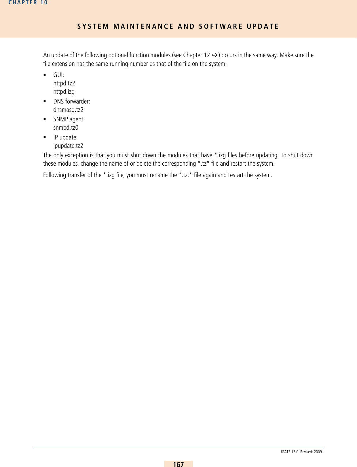
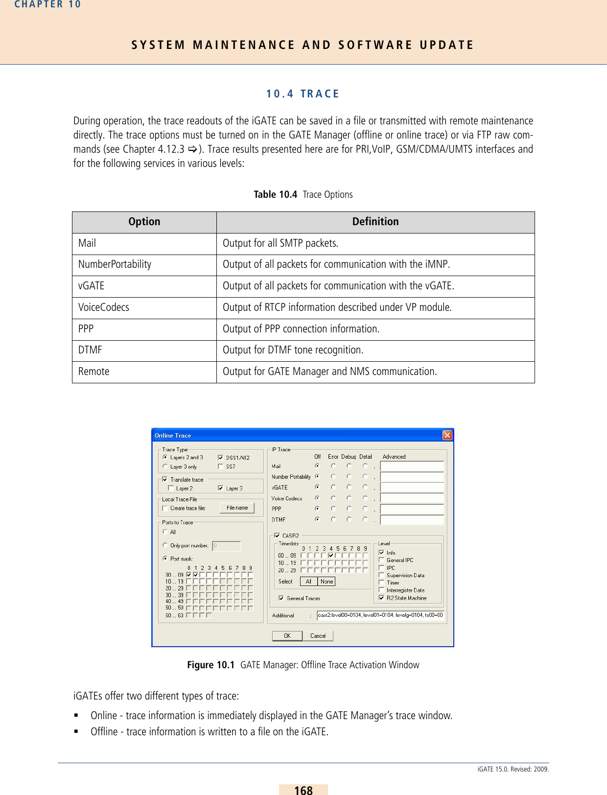
![SYSTEM MAINTENANCE AND SOFTWARE UPDATECHAPTER 10169iGATE 15.0. Revised: 2009.iGATE systems create trace files when the TraceLog=file entry is present in the pabx.cfg. Traces can be activatedvia remote administration (GATE Manager or FTP). Trace Output FormatThe following entries appear at the beginning and end of each trace:DD.MM.YY-hh:mm:ss.ss, StartDD.MM.YY-hh:mm:ss.ss, End– DD = day– hh = hour–MM = month– mm = minute–YY = year– ss.ss = hundredths of secondsTraces appear in the following format:[<hh:mm:ss>] <module>[<port>]: <trace><module> – s = send for PRI/BRI or mobile ports– r = receive for PRI/BRI or mobile ports– x = send to VoIP destinations– y = receive from VoIP destinations– i = information messages and internal trace outputs between VoIP and the other interfaces (ISDN,mobile)– a = VoIP controllers RTCP output–m = mail output– g = remote output<port> – port number (controller number in the pabx.cfg) or 255 if a service is used<trace>– output in the defined syntax for the moduleTable 10.5 Please bear in mind that the volume of trace readouts can grow quite large, so that faulty transmission of the trace data may result with remote maintenance. A trace at full capacity can cause the system to crash.ii](https://usermanual.wiki/Teles-Informationstechnologien/GSM32VOIPUS/User-Guide-1224551-Page-169.png)
![SYSTEM MAINTENANCE AND SOFTWARE UPDATECHAPTER 10170iGATE 15.0. Revised: 2009.10.4.1 ISDN TRACE OUTPUTTrace output for DSS1 are in hexadecimal notation. You can use the external tool TraceView.exe to translate offlinetrace output. You will find the tool in the Software folder on the enclosed CD. The GATE Manager’s trace windowcan also display translated online traces.Example: The following example shows an untranslated DSS1 trace: 10.4.2 GSM/CDMA/UMTS TRACE OUTPUTThe trace output for GSM appears in hexadecimal notation. Its format is the same as that for ISDN output. Table10.6 > and Table 10.7 > describe the contents of GSM trace output. 17.05.06-09:54:40,Start 11.7a (L3)[09:55:14.58] r[00]: 00 01 02 02 08 02 00 02 05 04 03 80 90 a3 18 03 a1 83 81 6c 02 81 31 70 06 81 31 32 33 34 35 7d 02 91 81 [09:55:14.58] s[00]: 02 01 02 04 08 02 80 02 0d 18 03 a9 83 81 [09:55:14.58] s[01]: 00 01 a8 9a 08 02 00 46 05 04 03 80 90 a3 18 03 a1 83 89 6c 02 81 31 70 06 81 31 32 33 34 35 7d 02 91 81 [09:55:14.58] r[01]: 02 01 9a aa 08 02 80 46 0d 18 03 a9 83 89 [09:55:14.86] r[01]: 02 01 9c aa 08 02 80 46 01 [09:55:14.86] s[00]: 02 01 04 04 08 02 80 02 01 [09:55:16.73] r[01]: 02 01 9e aa 08 02 80 46 07 29 05 05 07 01 09 33 4c 07 01 81 31 32 33 34 35 [09:55:16.73] s[01]: 00 01 aa a0 08 02 00 46 0f [09:55:16.73] s[00]: 02 01 06 04 08 02 80 02 07 29 05 05 07 01 09 32 4c 07 01 81 31 32 33 34 35[09:55:16.73] r[00]: 00 01 04 08 08 02 00 02 0f [09:55:44.30] r[00]: 00 01 06 08 08 02 00 02 45 08 02 80 90 [09:55:44.35] s[01]: 00 01 ac a0 08 02 00 46 45 08 02 80 90 [09:55:46.71] r[01]: 02 01 a0 ae 08 02 80 46 4d [09:55:46.71] s[01]: 00 01 ae a2 08 02 00 46 5a [09:55:46.71] s[00]: 02 01 08 08 08 02 80 02 4d [09:55:46.71] r[00]: 00 01 08 0a 08 02 00 02 5a 17.05.06-09:51:33,EndTable 10.6 Request Messages to the GSM Module Hex Value Description00 Setup01 Connect02 Disconnect03 SMS04 DTMF05 Set Config06 Get Config07 LED08 Restart09 Switch SIM](https://usermanual.wiki/Teles-Informationstechnologien/GSM32VOIPUS/User-Guide-1224551-Page-170.png)
![SYSTEM MAINTENANCE AND SOFTWARE UPDATECHAPTER 10171iGATE 15.0. Revised: 2009.Example: The following example shows a GSM call through the fourth GSM controller:10.4.3 VOIP TRACE OUTPUTAs described above in Chapter 10.4 >, there are four modules for VoIP traces. The groups x (send), y (receive)and i (information and internal output) appear when a Layer2 or Layer3 offline or online trace is started. Group a(RTCP output) only appears when the module Voice Codecs is active.Table 10.7 Incoming, Indication Message from the GSM Module Hex Value Description0B Alert0C Voice Indication0D Connect0E DTMF0F Setup10 Disconnect11 SMS12 SMS Confirmation13 Error16 Get Config Confirmation18 Dial-End Call Proceeding19 USSD1A Restart IndicationStatus Request[14:57:51.80] s[04]: 06Status Information: [14:57:51.80] r[04]: 16 Setup Request:[14:57:52.29] s[04]: 00 4c 93 04 00 00 00 35 36 36 37 00 35 38 2c 36 34 36 2c 33 30 2c 2c 2c 30 2c 2c 2c 30 2c 32 36 32 2c 30 37 2c 00 72 64 09 75 70 20 7b 64 35 7d 20 27 2e 2e 2b 43 43 45 44 3a 20 32 36 32 2c 30 37 2c 34 Dial End:[14:57:55.47] r[04]: 18 Alert:[14:57:55.63] r[04]: 0b Connect Indication:[14:57:56.63] r[04]: 0d Disconnect Request:[14:59:54.13] s[04]: 02 4c 93 00 Disconnect Indication:[14:59:54.19] r[04]: 10](https://usermanual.wiki/Teles-Informationstechnologien/GSM32VOIPUS/User-Guide-1224551-Page-171.png)
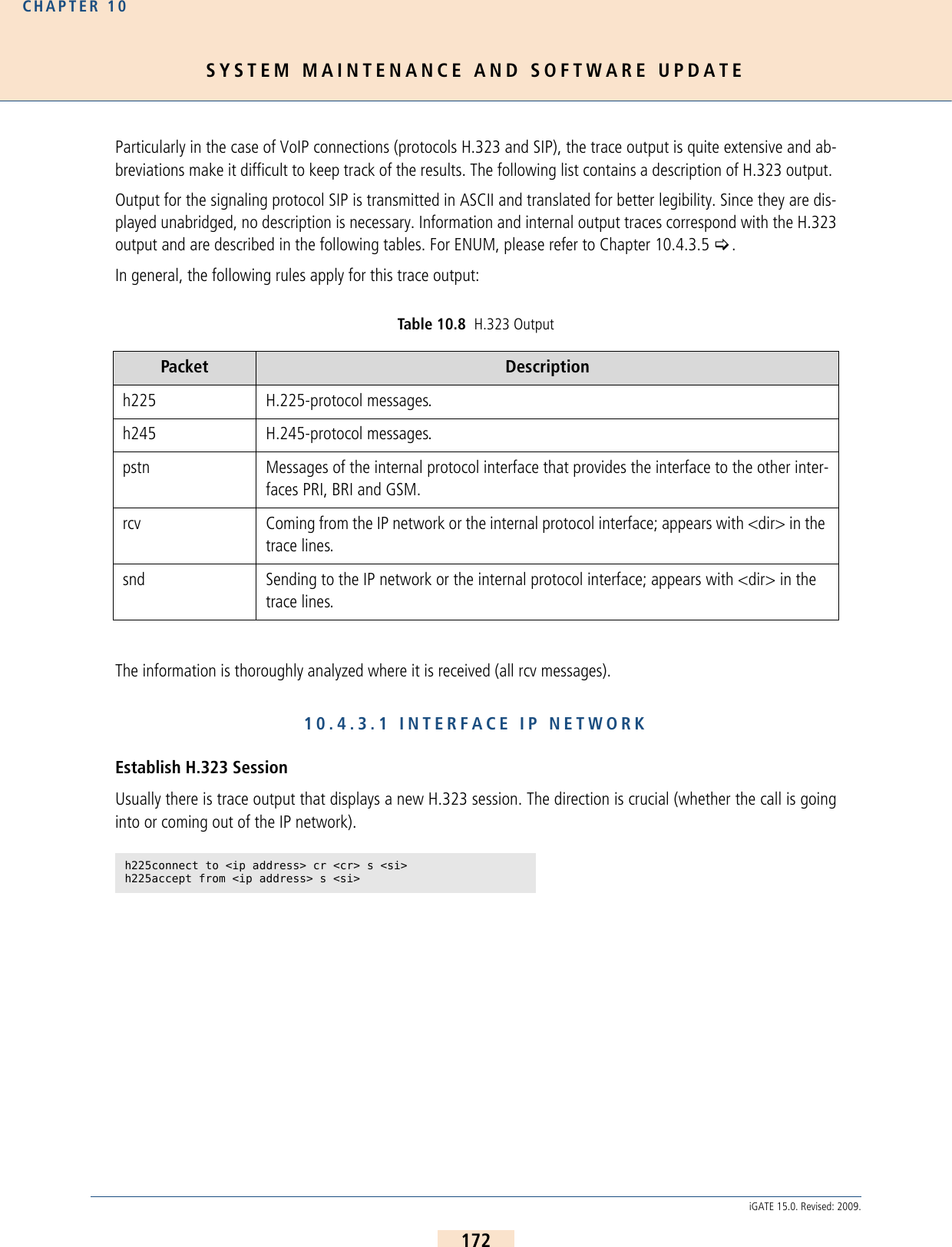
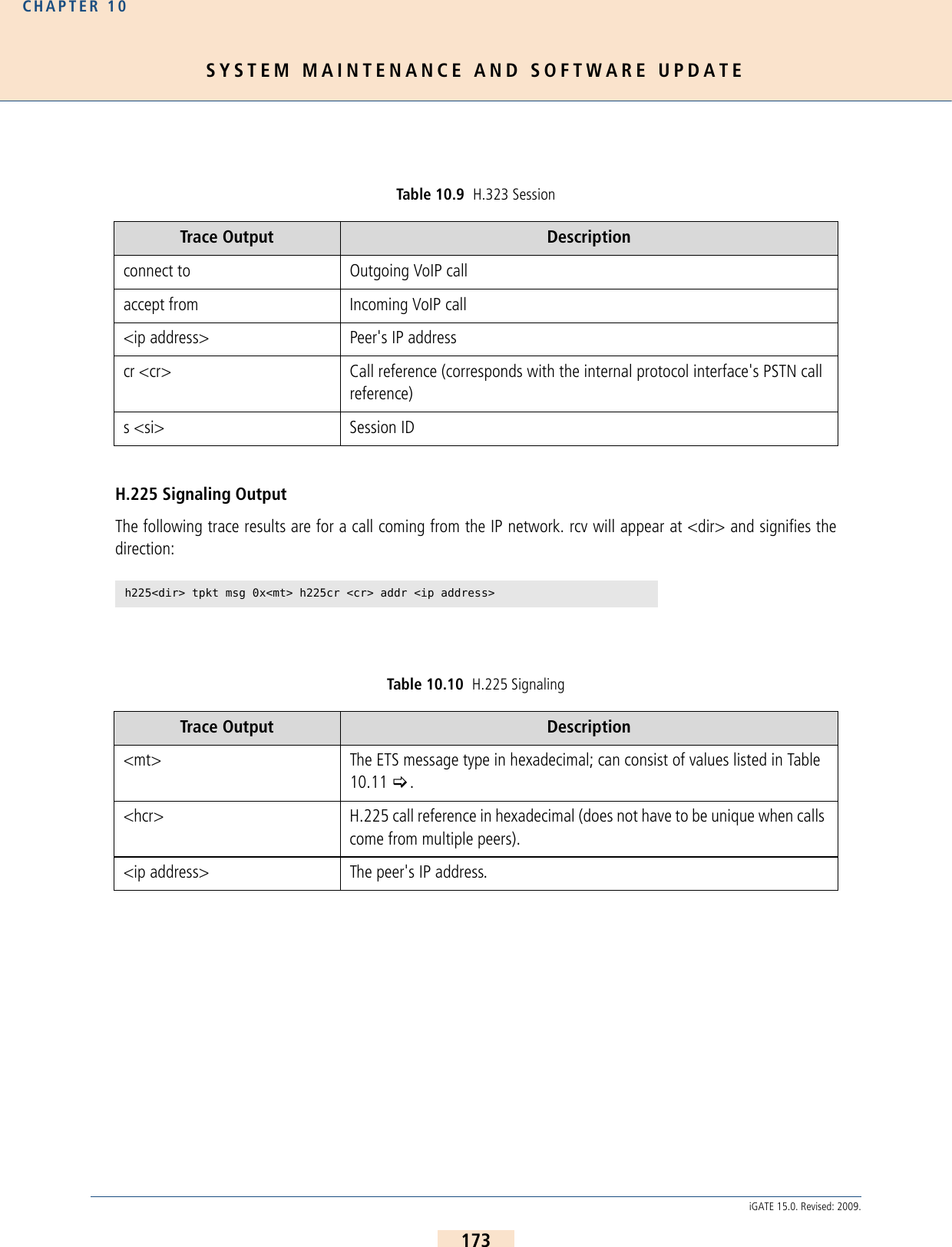
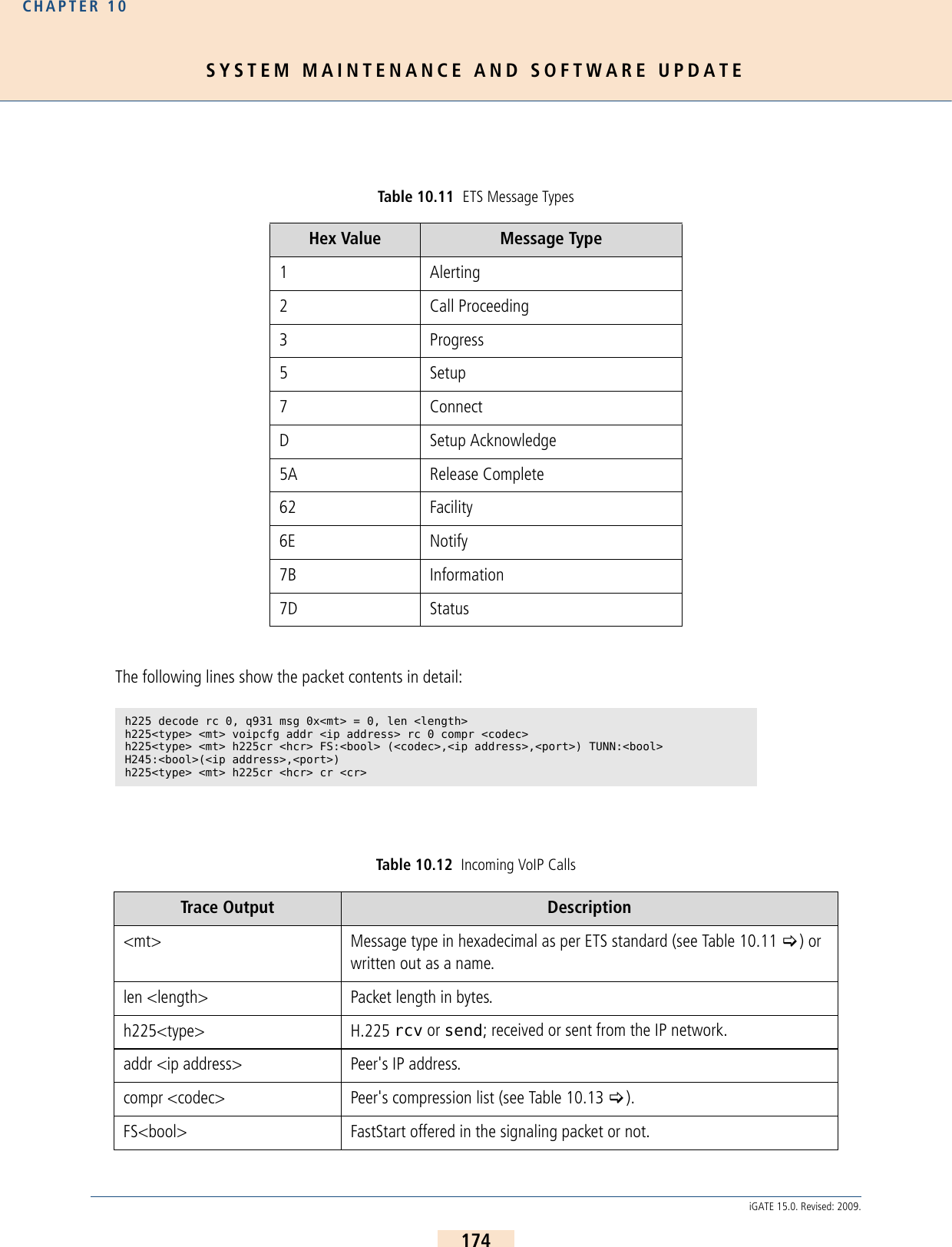
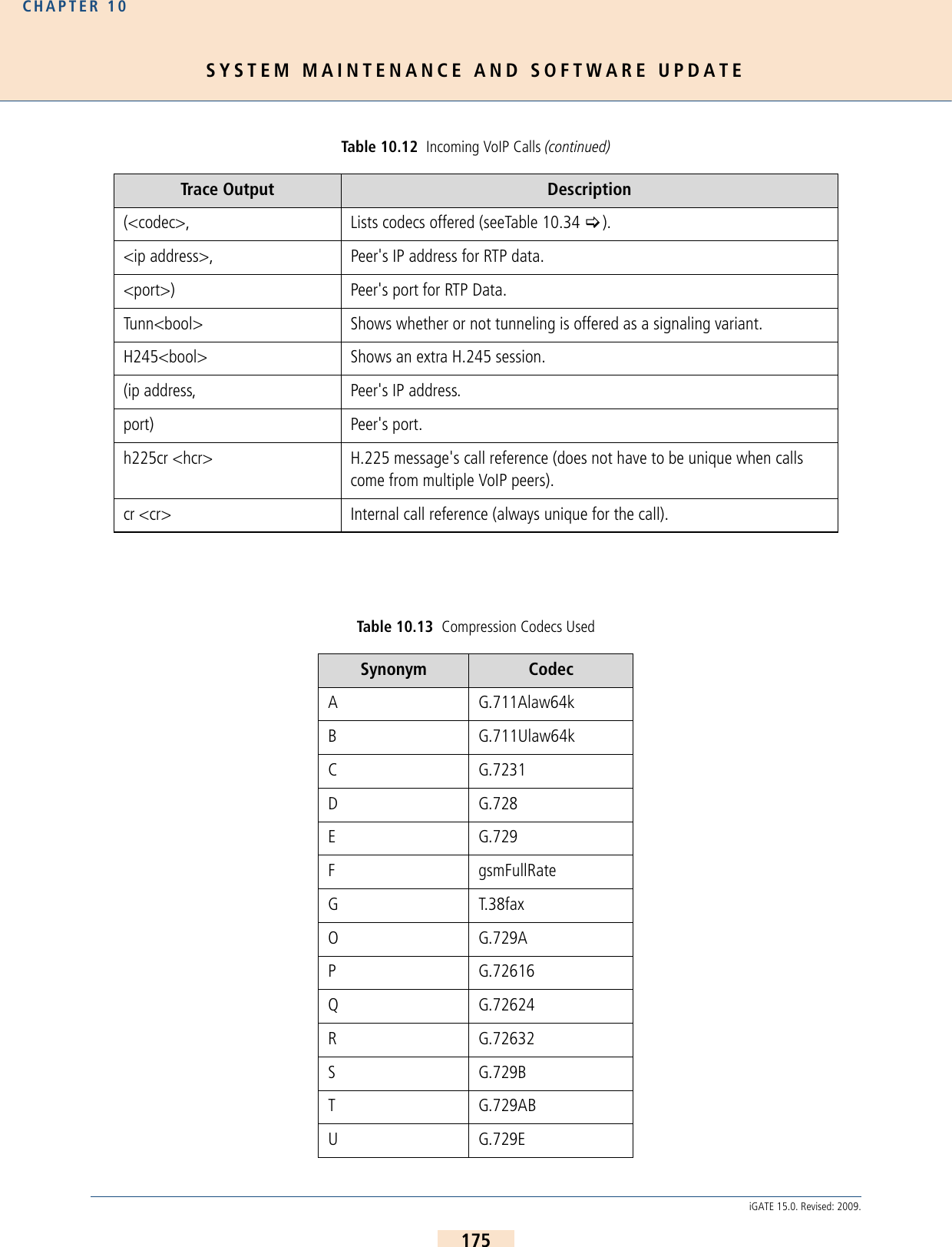
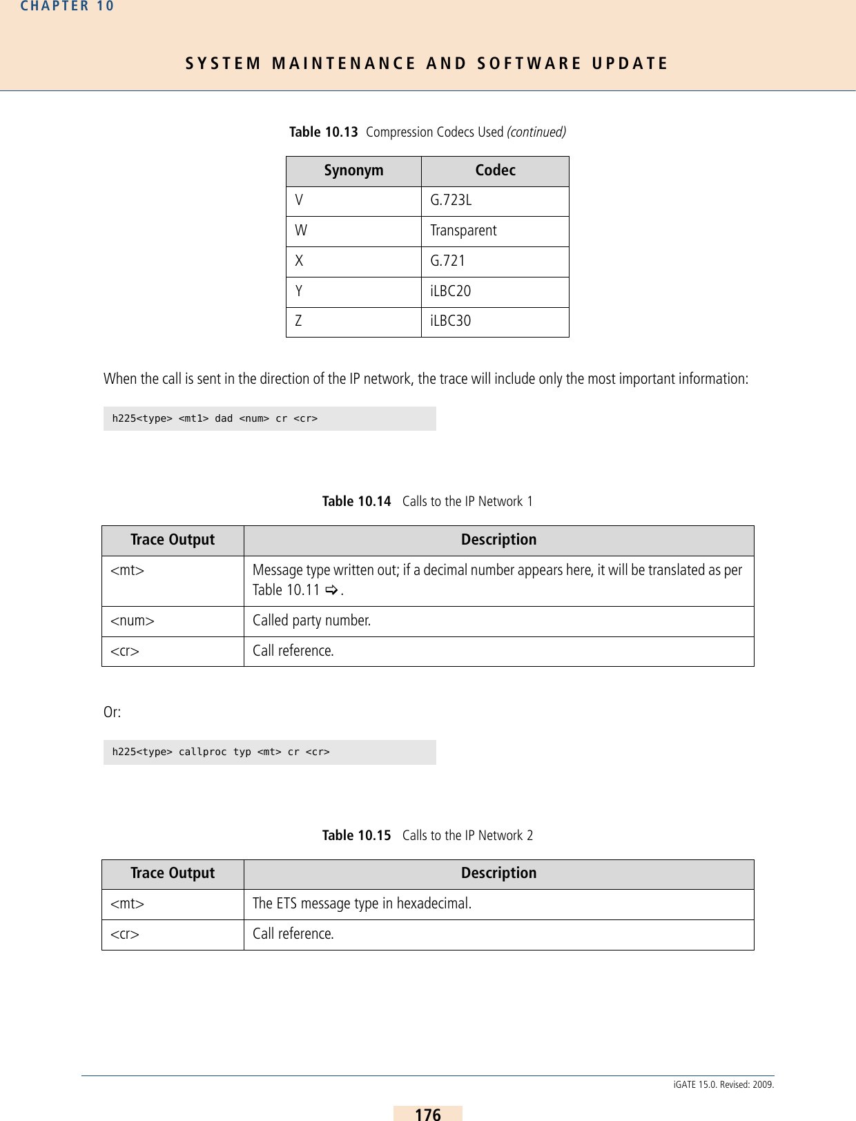
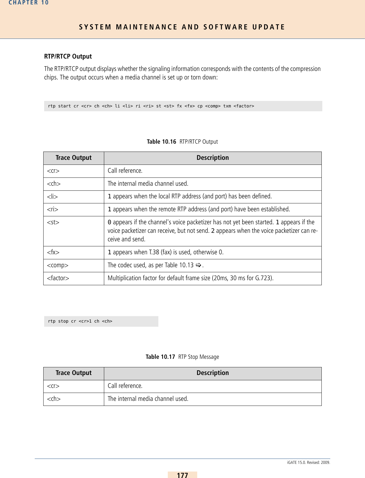
![SYSTEM MAINTENANCE AND SOFTWARE UPDATECHAPTER 10178iGATE 15.0. Revised: 2009.The following output shows the jitter buffer status:Table 10.18 RTP Packet Statistics Trace Output Description<ch> The internal media channel used.<byte> The call's received or sent bytes.rtcp <ch>: SR <dir> pc <pc> oc <oc> ji <ji> rt <rt> fl <fl> cl <cl>Table 10.19 RTCP Packet Statistics Trace Output Description<ch> The internal media channel used.SR<dir> Rx sender report (received) is more interesting, since it comes from the peer. Tx sender report (transmitted).<pc> Packet count (number of packets transmitted/received).<oc> Octet count (number of octets transmitted/received).<ji> Delay jitter [msec].<rt> Round-trip local<->remote, round-trip delay [msec].<fl> Fraction lost: Fraction of packets lost [8lsb].<cl> Cumulative lost: number of lost packets [24lsb].a[<controller>]: <VoIPcodecChipType> ch <ch> jitter buffer n1 n2 n3n4 n5 n6 n7 n8Table 10.20 Jitter Buffer Status Trace Output Descriptionn1 SteadyStateDelay in milliseconds](https://usermanual.wiki/Teles-Informationstechnologien/GSM32VOIPUS/User-Guide-1224551-Page-178.png)
![SYSTEM MAINTENANCE AND SOFTWARE UPDATECHAPTER 10179iGATE 15.0. Revised: 2009.An RTP connection has ended when the following trace output appears:The following output results when the codec changes for a fax connection: n2 NumberOfVoiceUnderrunn3 NumberOfVoiceOverrunn4 NumberOfVoiceDecoderBfi (bfi = bad frame interpolation)n5 NumberOfVoicePacketsDroppedn6 NumberOfVoiceNetPacketsLostn7 NumberOfIbsOverrun (ibs = in band signaling)n8 NumberOfCasOverruna[<controller>]: <VoIPcodecChipType> stop ch=<ch>Table 10.21 RTP Stop Message (VP Module) Trace Output Description<ch> The internal media channel used.a[<controller>]: ac49x ch <ch> fax/data n1 n2 n3Table 10.22 Codec Change for Fax Trace Output Descriptionn1 Fax bypass flag:0Voice, data bypass or fax relay1Fax bypassn2 Signal detected on decoder output (see Table 10.23)n3 Signal detected on encoder input (see Table 10.23)Table 10.20 Jitter Buffer Status (continued)Trace Output Description](https://usermanual.wiki/Teles-Informationstechnologien/GSM32VOIPUS/User-Guide-1224551-Page-179.png)
![SYSTEM MAINTENANCE AND SOFTWARE UPDATECHAPTER 10180iGATE 15.0. Revised: 2009.Fax relay is activated for the corresponding channel: Table 10.23 faxordatasignalevent Value Definition Description0 SILENCE_OR_UNKNOWN Undefined (unknown signal or silence)1 FAX_CNG CNG-FAX (calling fax tone, 1100 Hz)2 ANS_TONE_2100_FAX_CED_OR_MODEMFAX-CED or modem-ANS (answer tone, 2100 Hz)3 ANS_TONE_WITH_REVERSALS ANS (answer tone with reversals)4 ANS_TONE_AM ANSam (AM answer tone)5 ANS_TONE_AM_REVERSALS ANSam (AM answer tone with reversals)6 FAX_V21_PREAMBLE_FLAGS FAX-V.21 preamble flags7 FAX_V8_JM_V34 FAX-V.8 JM (fax call function, V.34 fax)8 VXX_V8_JM_VXX_DATA V.XX-V.8 JM (data call function, V-series mo-dem)9 V32_AA V.32 AA (calling modem tone, 1800 Hz)10 V22_USB1 V.22 USB1 (V.22(bis) unscrambled binary ones)11 V8_BIS_INITIATING_DUAL_TONE V.8bis initiating dual tone (1375 Hz and 2002 Hz)12 V8_BIS_RESPONDING_DUAL_TONE V.8bis responding dual tone (1529 Hz and 2225 Hz)13 VXX_DATA_SESSION V.XX data session14 V21_CHANNEL_2 V.21 channel 2 (mark tone, 1650 Hz)15 V23_FORWARD_CHANNEL V.23 forward channel (mark tone, 1300 Hz)16 V21_CHANNEL_1=18 V.21 channel 1 (mark tone, 980 Hz)17 BELL_103_ANSWER_TONE Bell 103 answer tone, 2225 Hz18 TTY TTY19 FAX_DCN FAX-DCN (G.3 fax disconnect signal)a[<controller>]: Ac49xActivateFaxRelayCommand(1) ch <ch> rc <cr>](https://usermanual.wiki/Teles-Informationstechnologien/GSM32VOIPUS/User-Guide-1224551-Page-180.png)
![SYSTEM MAINTENANCE AND SOFTWARE UPDATECHAPTER 10181iGATE 15.0. Revised: 2009.The following output shows various values for fax transmission (see Table 10.24 for a description of the values): a[<controller>]: ac49x ch <ch> faxrelay: n1 n2 n3 n4 n5 n6 n7 n8 n9 n10 n11 n12 n13 n14Table 10.24 Fax Status Value Descriptionn1 UnableToRecoverFlag (0 no, 1 yes)n2 IllegalHdlcFrameDetectedFlag (...)n3 FaxExitWithNoMcfFrameFlagn4 HostTransmitOverRunFlagn5 HostTransmitUnderRunFlagn6 InternalErrorFlagn7 ReceivedBadCommandFlagn8 TimeOutErrorFlagn9 TxRxFlag (0 receive, 1 transmit)](https://usermanual.wiki/Teles-Informationstechnologien/GSM32VOIPUS/User-Guide-1224551-Page-181.png)
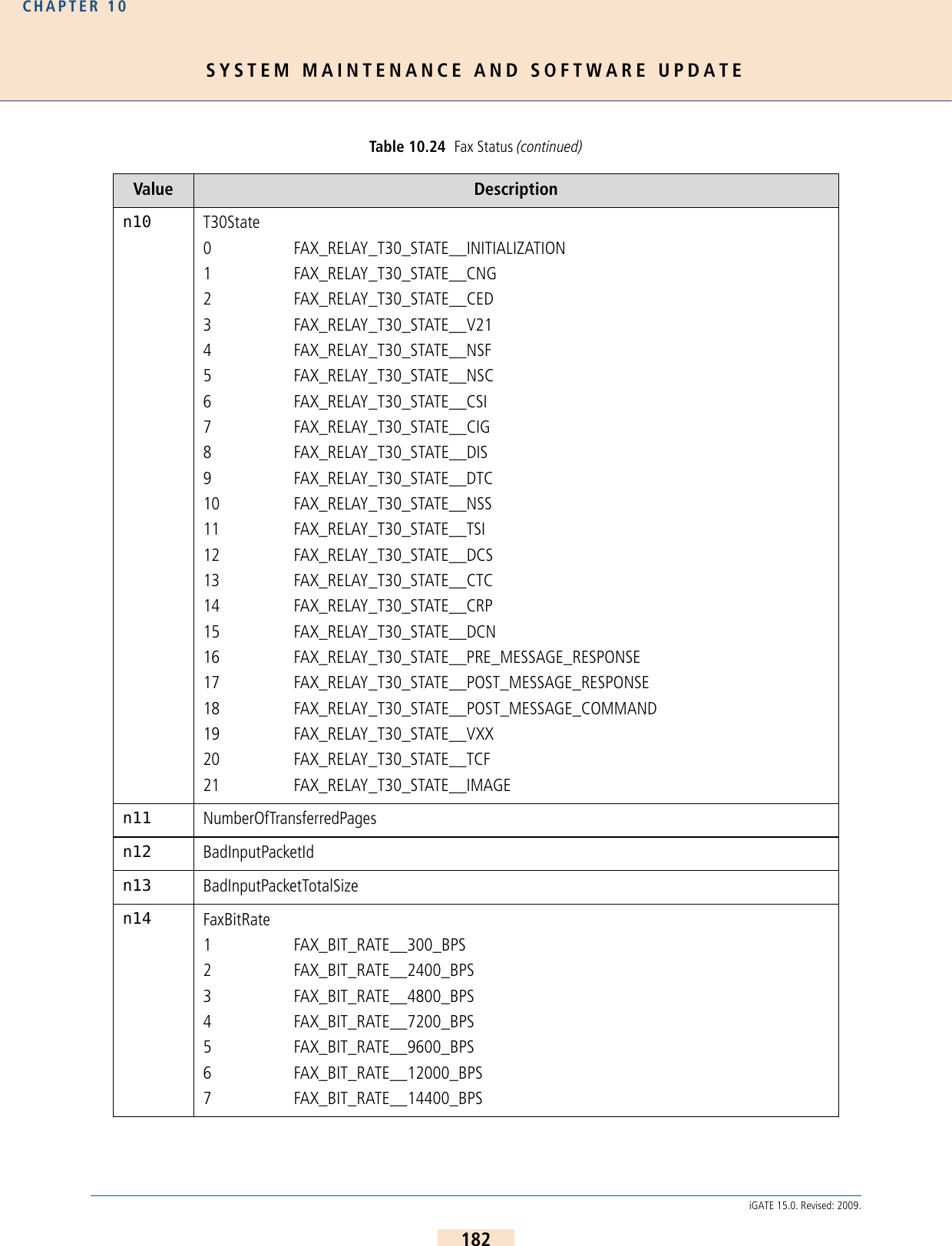
![SYSTEM MAINTENANCE AND SOFTWARE UPDATECHAPTER 10183iGATE 15.0. Revised: 2009.The following output appears when the compression chip recognizes DTMF tones:10.4.3.2 INTERNAL PROTOCOL INTERFACE (TO ISDN, MOBILE)These trace outputs always begin with the keyword pstn, followed by the direction and the message type. Themessage is then either concluded or other information follows: a[<controller]: ac49x ch <ch> ibs <dtmf> <dir> <mode> <lev> <dur>Table 10.25 DTMF Tone RecognitionTrace Output Description<ch> Media channel<dtmf> Recognized DTMF tone in the stream or as per RFC2833<dir> Direction0Coming from BRI/analog1Coming from VoIP<mode> 0Tone has ended1Tone has been recognized<lev> Signal level in -dBm<dur> Tone durationpstn<type> <mt1> dad <num> oad <num> cc <value> cc <cc> id <id> c/c <ctrl>/<ch> cr <cr> Table 10.26 Internal Protocol Interface Trace Output Description<type> Direction from (rcv) or to (snd) the internal protocol interface.<mt1> Message type written out; if a decimal number appears, it will be translated as per Table 10.11.<num> DAD<num> = called party number, OAD<num> = calling party number.](https://usermanual.wiki/Teles-Informationstechnologien/GSM32VOIPUS/User-Guide-1224551-Page-183.png)
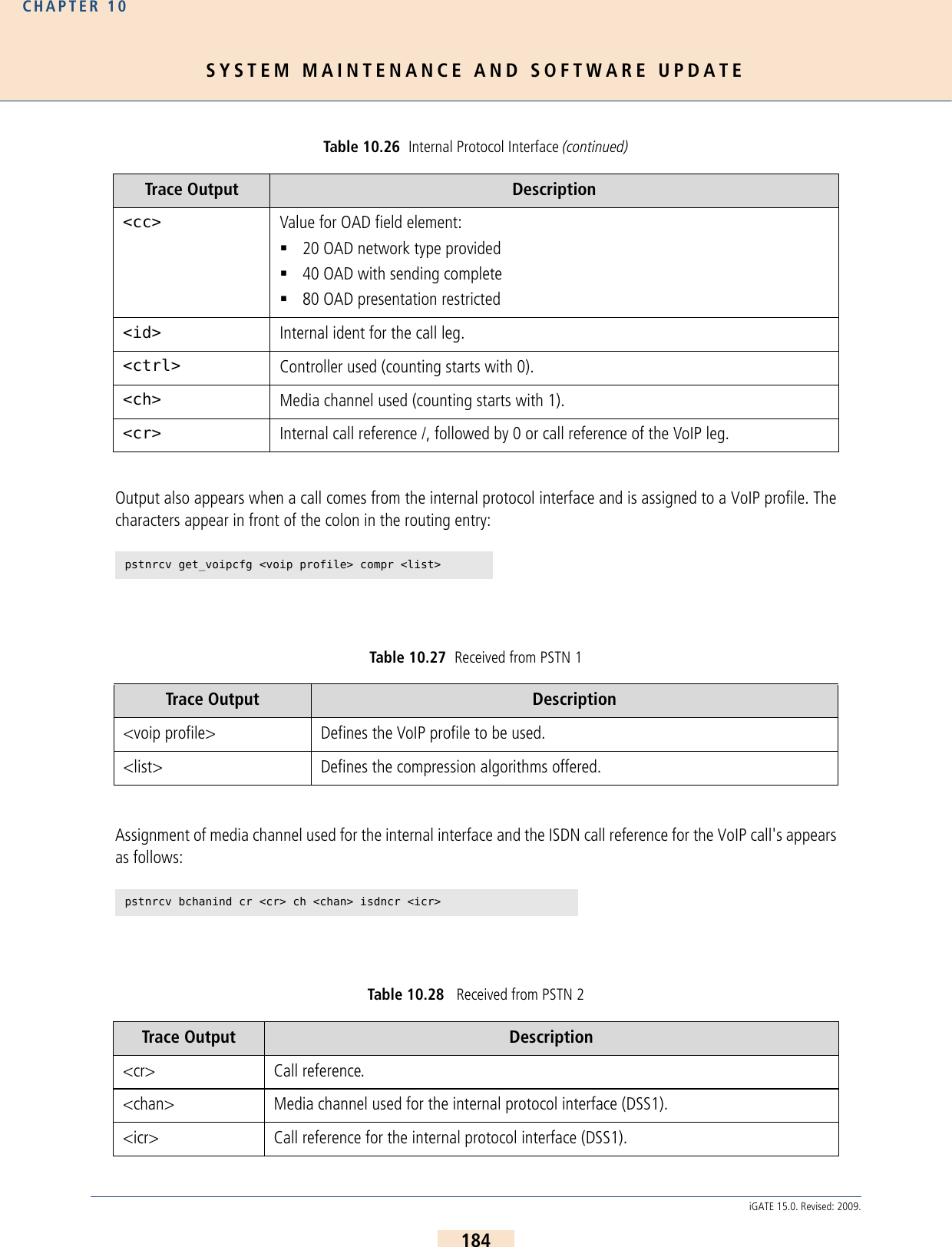
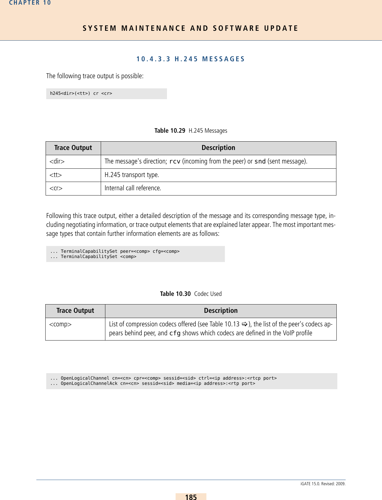
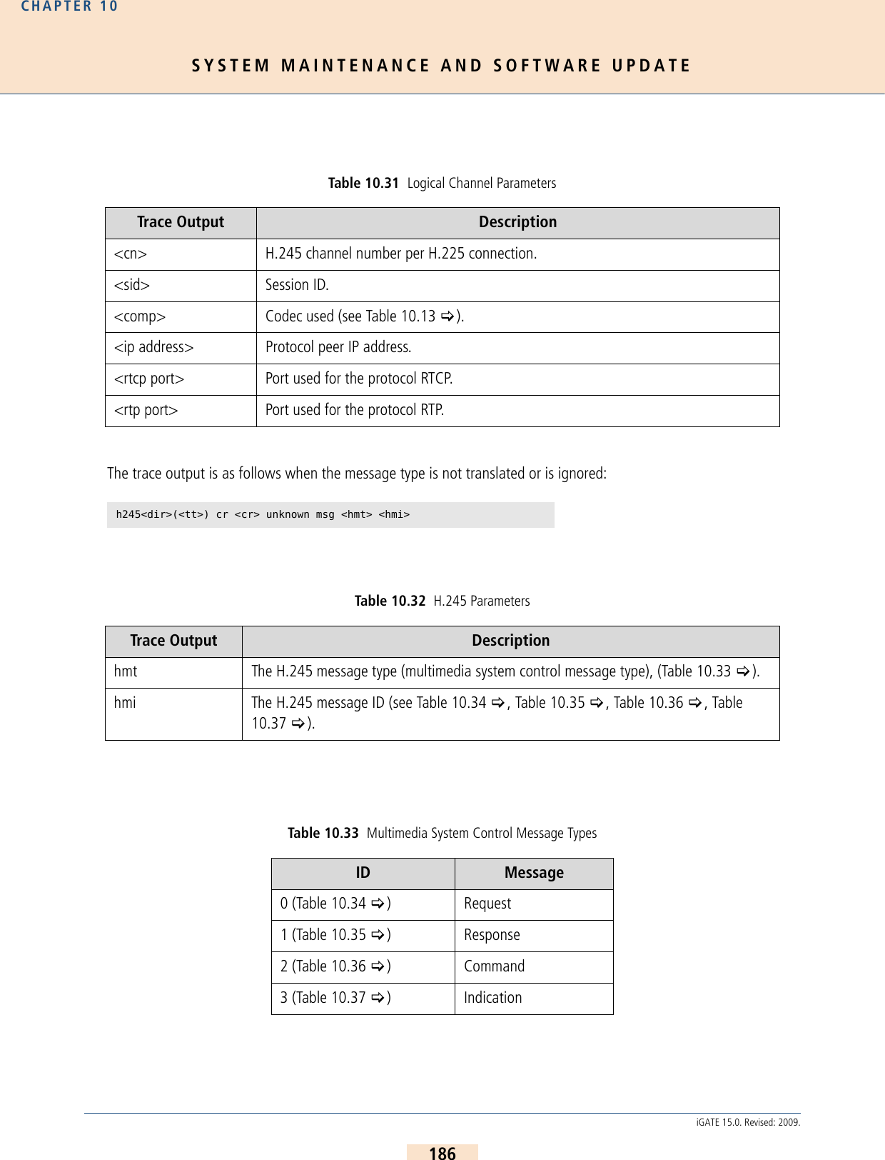
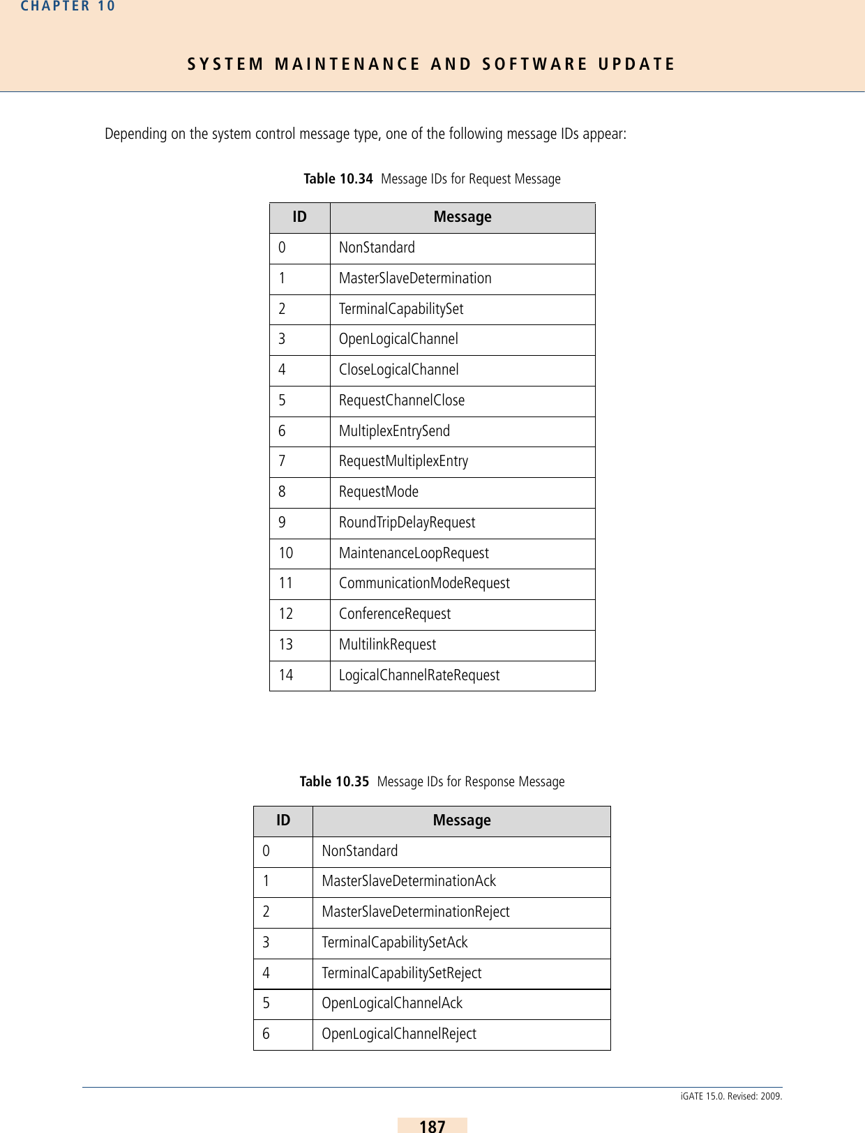
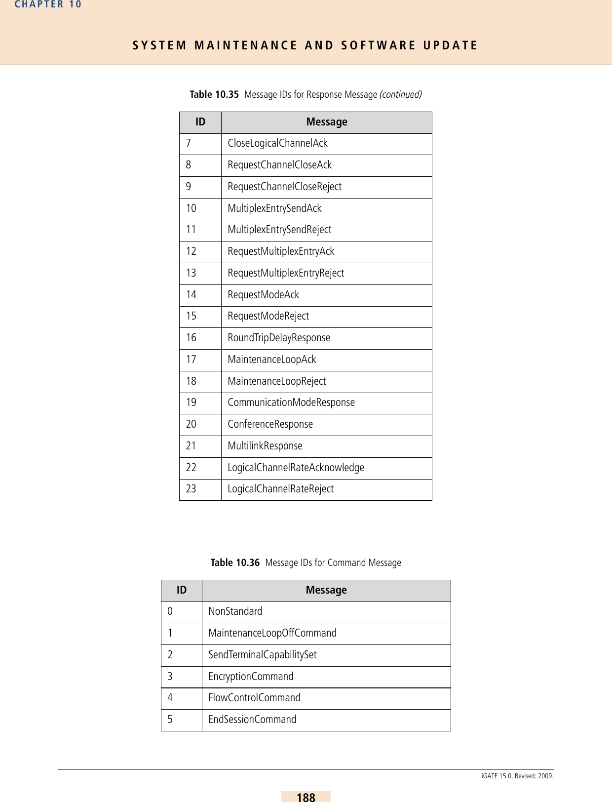
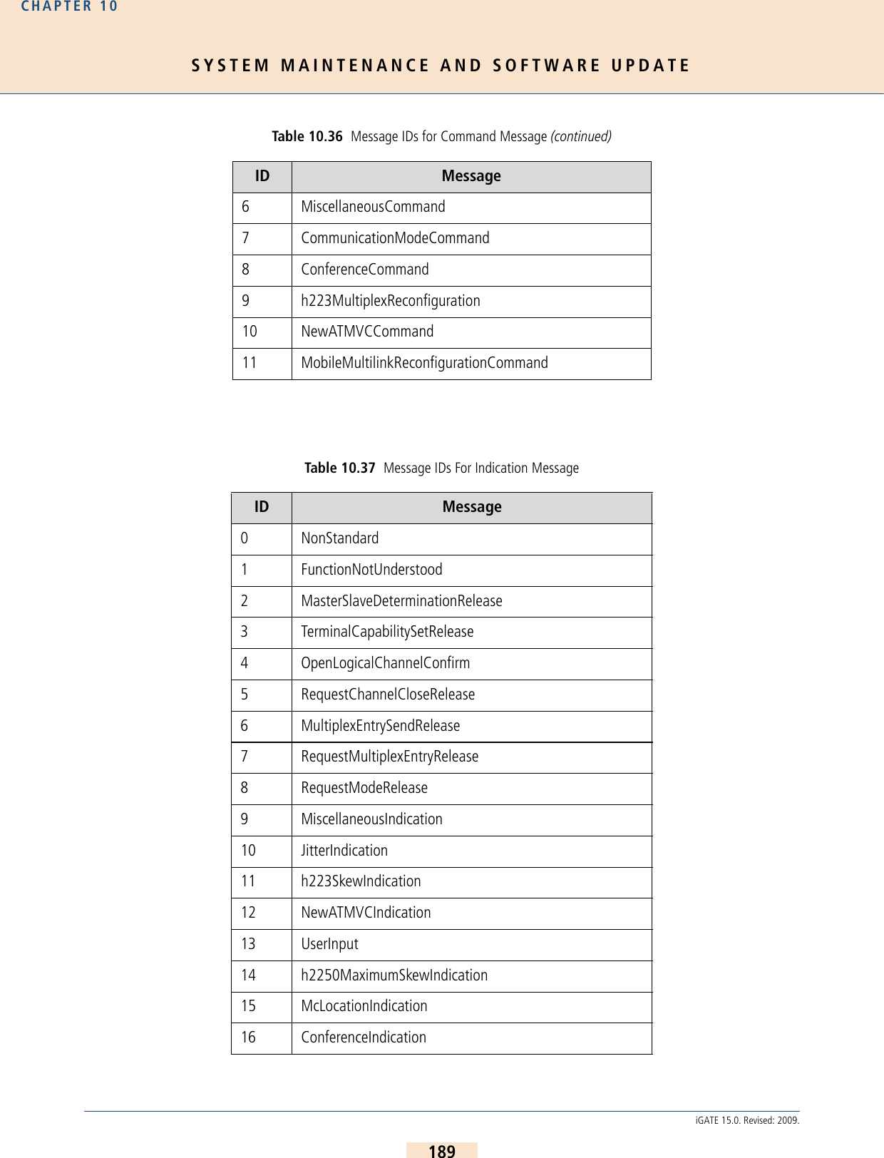
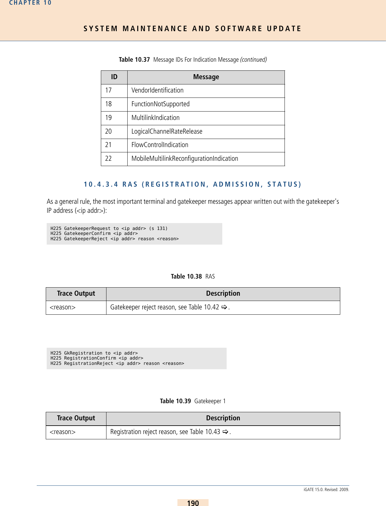
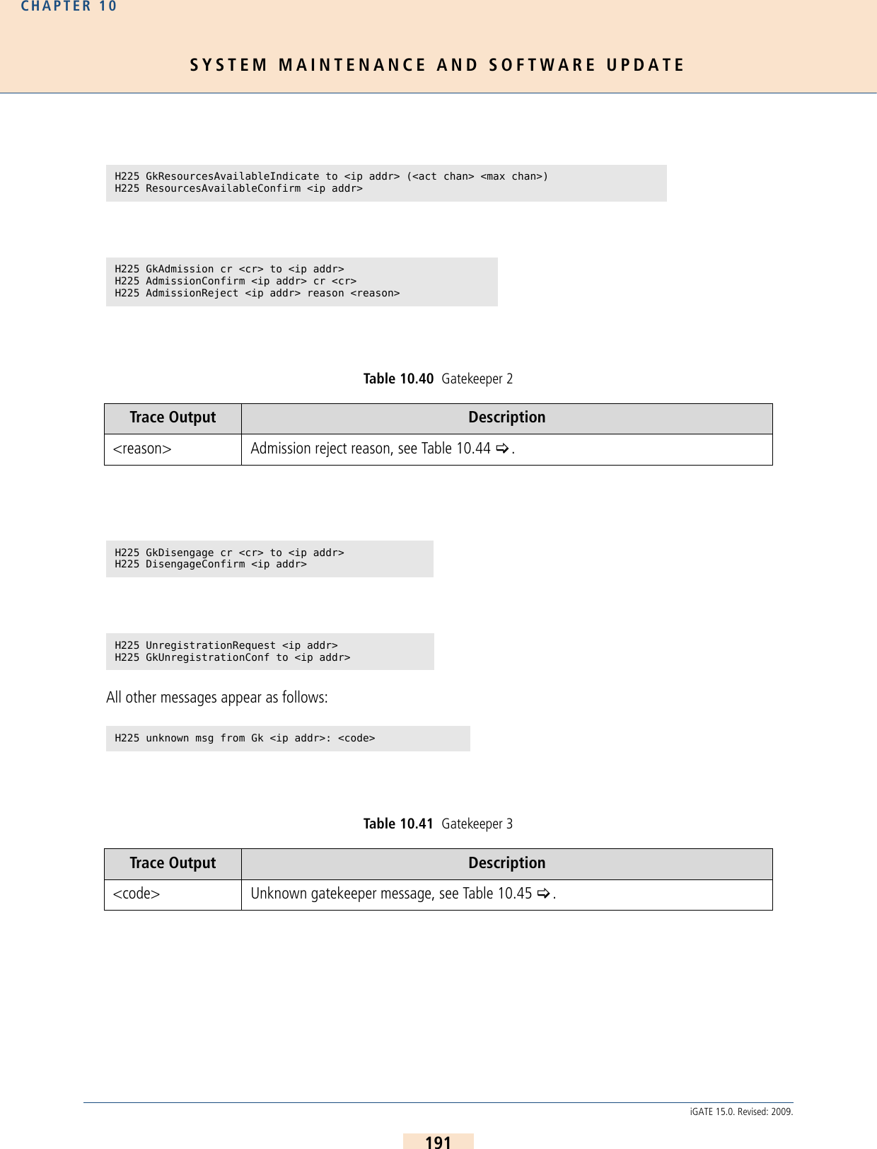
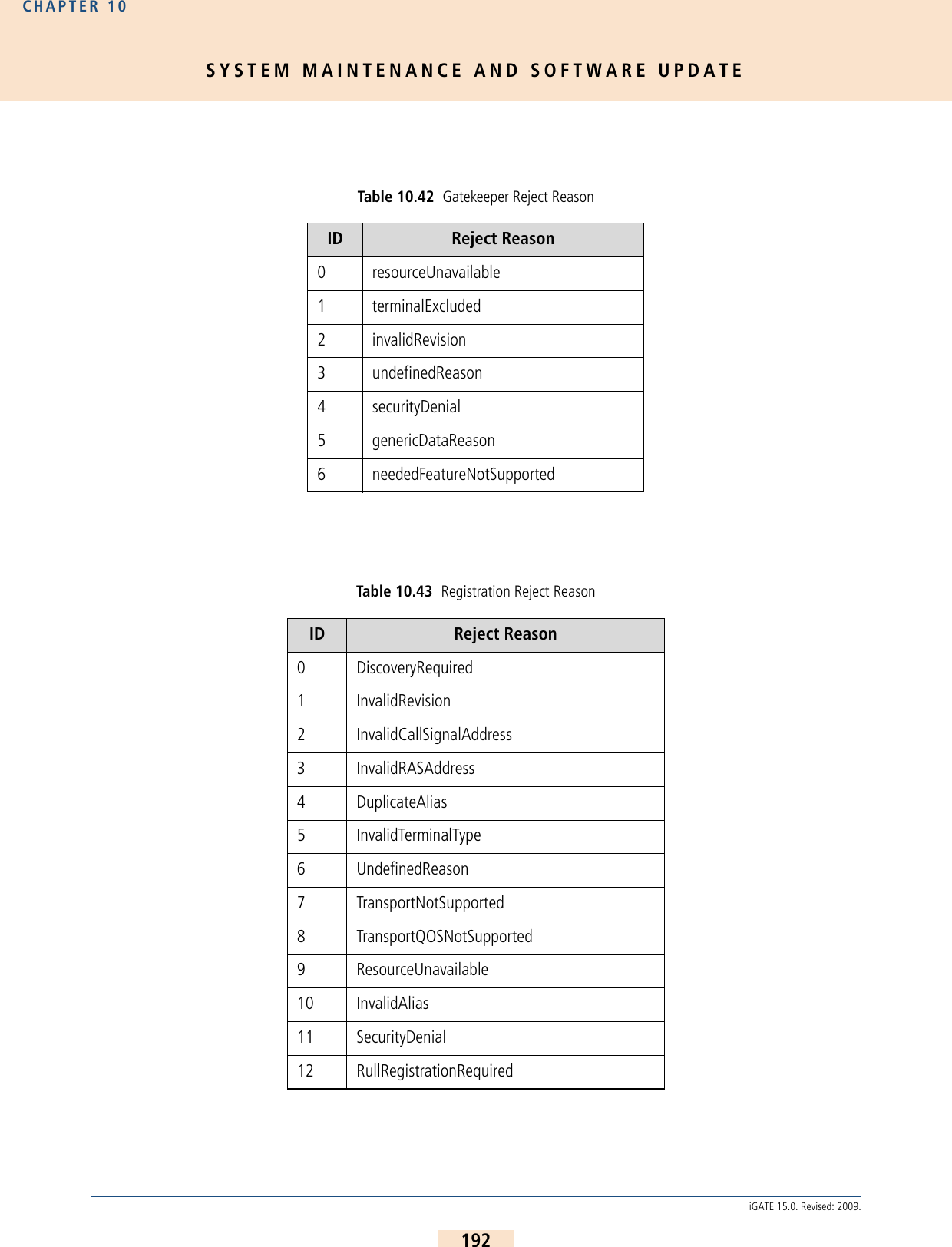
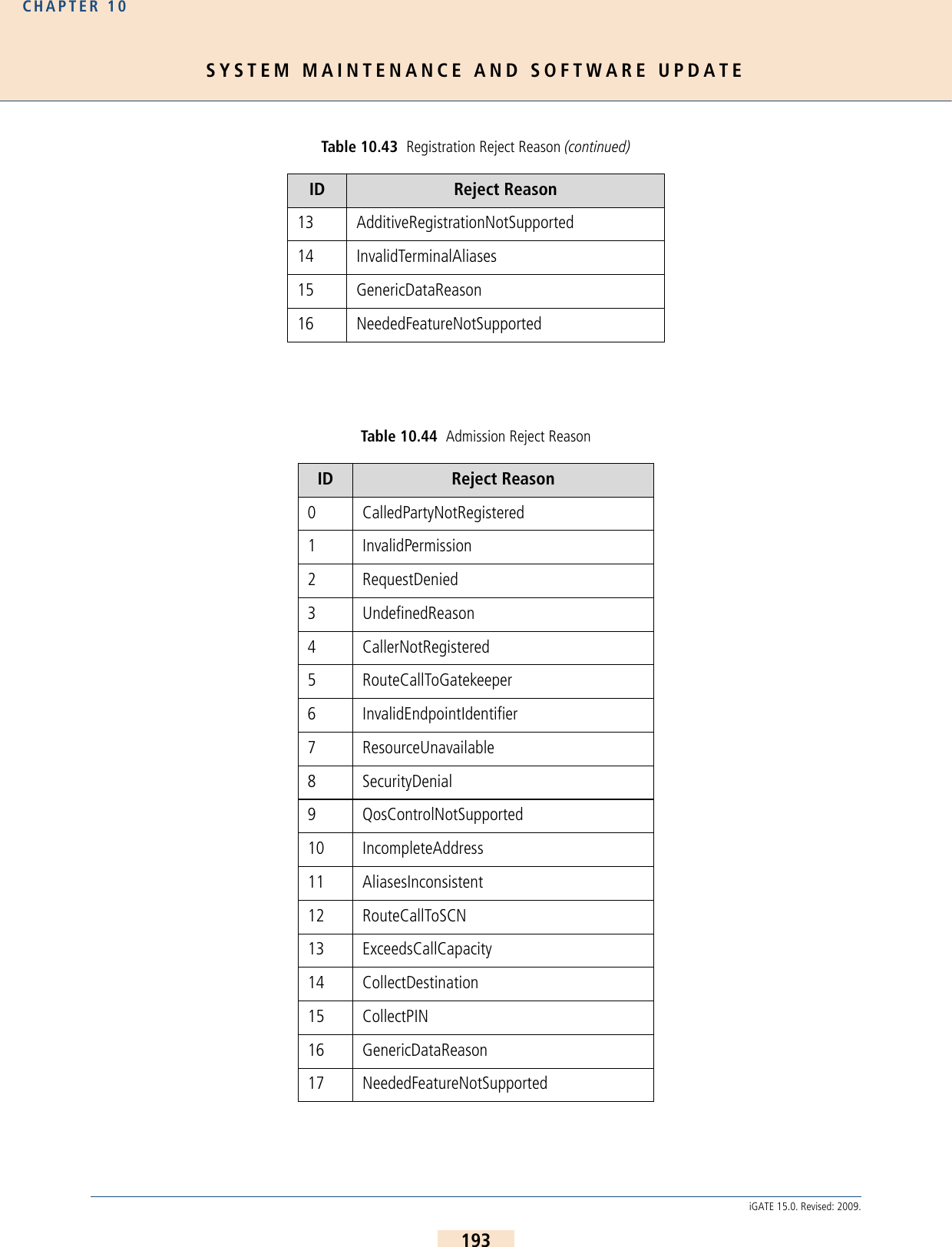
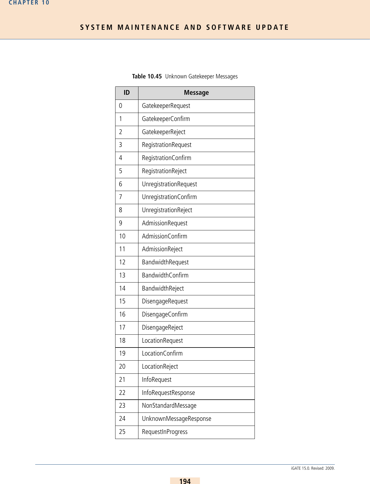
![SYSTEM MAINTENANCE AND SOFTWARE UPDATECHAPTER 10195iGATE 15.0. Revised: 2009.10.4.3.5 ENUM OUTPUTThis output is assigned to group i and occurs with Layer2 and Layer3 traces:10.4.3.6 EXAMPLESThe following examples are offline traces. You can generate them using the GATE Manager or FTP commands. Thefilename is trace.log. The following cases appear in the examples:Incoming H323 Call with FastStart > Outgoing H323 Call with FastStart >Fax Call > 26 ResourcesAvailableIndicate 27 ResourcesAvailableConfirm 28 InfoRequestAck 29 InfoRequestNak 30 ServiceControlIndication 31 ServiceControlResponse i[<controller>]: enum_query cr <CR> ch <CH>: <num> -> <length> <<answer pattern>>Table 10.46 ENUM Output Trace Output Description<cr> Call reference.<ch> Media channel.<num> Phone number converted into ENUM domain format.<length> Length of the answer field in the DNS response in bytes. 0 appears if the number was not found.<answer pattern> Displays the DNS response. 0 appears if the number was not found.Table 10.45 Unknown Gatekeeper Messages (continued)ID Message](https://usermanual.wiki/Teles-Informationstechnologien/GSM32VOIPUS/User-Guide-1224551-Page-195.png)
![SYSTEM MAINTENANCE AND SOFTWARE UPDATECHAPTER 10196iGATE 15.0. Revised: 2009.Incoming H323 Call with FastStart [15:25:13.65] i[02]: h225accept from 172.16.0.200 s 4[15:25:13.75] y[02]: h225rcv tpkt msg 5 h225cr 8006 addr 172.16.0.200 pt 0[15:25:13.75] y[02]: h225 decode rc 0, q931 msg 5 (0), len 364[15:25:13.75] y[02]: h225rcv setup voipcfg addr 172.16.0.200 rc 0 <DF> compr EABG[15:25:13.75] y[02]: h225rcv faststart <A1B1E1G0>[15:25:13.75] y[02]: h225rcv setup oad 01 00 <111> <> dad 01 <123456> rad <> bc 038090a3 0101[15:25:13.75] y[02]: h225rcv setup h225cr 8006 FS:1(E,172.16.0.200,29000) TUNN:1 H245:0(0,0)[15:25:13.75] y[02]: h225rcv setup h225cr 8006 cr 7[15:25:13.75] i[02]: pstnsnd setup dad 123456 oad 1 cr 7 s 4[15:25:13.75] s[00]: 00 01 52 4c 08 02 00 08 05 04 03 80 90 a3 18 03 a1 83 87 6c 04 81 31 31 31 70 07 81 31 32 33 34 35 36 7d 02 91 81 [15:25:13.75] i[02]: pstnrcv connresp cr 7 acc 5 ch 1[15:25:13.75] x[02]: h225snd callproc typ d cr 7 pri 0[15:25:13.75] r[00]: 00 01 01 54 [15:25:13.75] r[00]: 02 01 4c 54 08 02 80 08 0d 18 03 a9 83 87 [15:25:13.75] s[00]: 02 01 01 4e [15:25:14.33] r[00]: 02 01 4e 54 08 02 80 08 01 [15:25:14.33] s[00]: 02 01 01 50 [15:25:14.33] i[02]: pstnrcv alert cr 7 cls ff[15:25:14.33] i[02]: rtp start cr 7 ch 1 li 1 ri 1 st 2 fx 0 cp E txm 1[15:25:14.33] x[02]: h225snd callproc typ 1 cr 7 pri 8[15:25:14.34] a[02]: vp start(201) ch=0 local=29000 remote=ac1000c8:29000 agg=0 pcm=0[15:25:14.38] a[02]: vp rtcp 0: RR Tx pc 0 oc 0 ji -1 rt 0 fl -1 cl -1[15:25:14.38] a[02]: vp ch 0: in 0 out 74[15:25:15.57] r[00]: 02 01 50 54 08 02 80 08 07 29 05 06 03 18 0f 17 4c 06 01 81 31 37 33 31 [15:25:15.57] s[00]: 00 01 54 52 08 02 00 08 0f [15:25:15.57] i[02]: pstnrcv connresp cr 7 acc 10 ch 255[15:25:15.57] x[02]: h225snd callproc typ 7 cr 7 pri 0[15:25:15.58] r[00]: 00 01 01 56 [15:25:17.01] a[02]: vp rtcp 0: SR Rx pc 110 oc 1816 ji 158 rt -1 fl 2 cl 1[15:25:20.09] a[02]: vp rtcp 0: SR Tx pc 277 oc 5496 ji 164 rt 0 fl 0 cl 0[15:25:20.09] a[02]: vp ch 0: in 18166 out 20646[15:25:20.09] a[02]: vp rtcp 0: SR Rx pc 258 oc 4634 ji 208 rt -1 fl 0 cl 1[15:25:23.32] a[02]: vp rtcp 0: SR Tx pc 441 oc 8776 ji 176 rt 0 fl 0 cl 0[15:25:23.32] a[02]: vp ch 0: in 28966 out 32900[15:25:24.68] y[02]: h225rcv tpkt msg 5a h225cr 8006 addr 172.16.0.200 pt 800e7800[15:25:24.68] y[02]: h225 decode rc 0, q931 msg 5a (5), len 33[15:25:24.68] y[02]: h225rcv relack h225cr 8006 FS:0(-,0,0) TUNN:1 H245:0(0,0)[15:25:24.68] y[02]: h225rcv relack h225cr 8006 cau 0x10[15:25:24.68] i[02]: rtp hold cr 7 ch 1[15:25:24.68] s[00]: 00 01 56 52 08 02 00 08 45 08 02 80 90 [15:25:24.68] i[02]: h225 connection 4 terminated[15:25:24.69] r[00]: 00 01 01 58 [15:25:25.89] r[00]: 02 01 52 58 08 02 80 08 4d [15:25:25.89] s[00]: 00 01 58 54 08 02 00 08 5a [15:25:25.94] i[02]: pstnrcv terminate connection (3201) cr 7 cau 1 err 16 state 17 ch 1 rsid 1[15:25:25.94] i[02]: rtp stop cr 7 ch 1[15:25:25.94] r[00]: 00 01 01 5a [15:25:25.94] a[02]: vp ch 0: in 34096 out 38154[15:25:25.94] a[02]: vp stop ch=0](https://usermanual.wiki/Teles-Informationstechnologien/GSM32VOIPUS/User-Guide-1224551-Page-196.png)
![SYSTEM MAINTENANCE AND SOFTWARE UPDATECHAPTER 10197iGATE 15.0. Revised: 2009.Outgoing H323 Call with FastStart[15:04:09.12] r[00]: 02 01 46 48 08 02 22 54 05 04 03 80 90 a3 18 03 a9 83 94 6c 06 01 81 31 31 31 31 70 04 81 33 32 31 7d 02 91 81 [15:04:09.12] s[00]: 02 01 01 48 [15:04:09.12] s[00]: 00 01 48 48 08 02 a2 54 0d 18 03 a9 83 94 [15:04:09.12] i[02]: pstnrcv setup dad DF:321 oad 1111 cc 0 id 15d006[15:04:09.12] i[02]: pstnrcv get_voipcfg <DF>[15:04:09.12] i[02]: h225connect to 172.16.0.200 cr 6[15:04:09.12] x[02]: h225snd setup dad 1 cr 6[15:04:09.12] r[00]: 00 01 01 4a [15:04:09.15] y[02]: h225rcv tpkt msg d h225cr 6 addr 172.16.0.200 pt 80412800[15:04:09.15] y[02]: h225 decode rc 0, q931 msg d (11), len 32[15:04:09.15] y[02]: h225rcv msg d (11) h225cr 6 FS:0(-,0,0) TUNN:1 H245:0(0,0)[15:04:09.50] y[02]: h225rcv tpkt msg 1 h225cr 6 addr 172.16.0.200 pt 80412800[15:04:09.50] y[02]: h225 decode rc 0, q931 msg 1 (3), len 121[15:04:09.50] y[02]: h225rcv faststart <E1>[15:04:09.50] y[02]: h225rcv alert h225cr 6 FS:1(E,172.16.0.200,29000) TUNN:1 H245:0(0,0)[15:04:09.50] i[02]: rtp start cr 6 ch 1 li 1 ri 1 st 2 fx 0 cp E txm 1[15:04:09.50] s[00]: 00 01 4a 48 08 02 a2 54 01 1e 02 80 88 [15:04:09.50] a[02]: vp start(201) ch=0 local=29000 remote=ac1000c8:29000 agg=0 pcm=0[15:04:09.50] r[00]: 00 01 01 4c [15:04:09.53] a[02]: vp rtcp 0: RR Tx pc 0 oc 0 ji -1 rt 0 fl -1 cl -1[15:04:09.53] a[02]: vp ch 0: in 0 out 74[15:04:11.79] y[02]: h225rcv tpkt msg 7 h225cr 6 addr 172.16.0.200 pt 80412800[15:04:11.79] y[02]: h225 decode rc 0, q931 msg 7 (2), len 79[15:04:11.79] y[02]: h225rcv connect h225cr 6 FS:0(-,0,0) TUNN:1 H245:0(0,0)[15:04:11.79] i[02]: pstnsnd connect cr 6[15:04:11.79] s[00]: 00 01 4c 48 08 02 a2 54 07 [15:04:11.80] r[00]: 02 01 48 4e 08 02 22 54 0f [15:04:11.80] s[00]: 02 01 01 4a [15:04:12.50] a[02]: vp rtcp 0: SR Rx pc 21 oc 394 ji 201 rt -1 fl 0 cl 0[15:04:16.13] a[02]: vp rtcp 0: SR Tx pc 192 oc 3236 ji 196 rt 0 fl 0 cl 0[15:04:16.13] a[02]: vp ch 0: in 14612 out 13796[15:04:17.98] y[02]: h225rcv tpkt msg 5a h225cr 6 addr 172.16.0.200 pt 80412800[15:04:17.98] y[02]: h225 decode rc 0, q931 msg 5a (5), len 33[15:04:17.98] y[02]: h225rcv relack h225cr 6 FS:0(-,0,0) TUNN:1 H245:0(0,0)[15:04:17.98] y[02]: h225rcv relack h225cr 6 cau 0x10[15:04:17.98] i[02]: rtp hold cr 6 ch 1[15:04:17.98] s[00]: 00 01 4e 4a 08 02 a2 54 45 08 02 80 90 [15:04:17.98] i[02]: h225 connection 4 terminated[15:04:17.99] r[00]: 00 01 01 50 [15:04:18.04] r[00]: 02 01 4a 50 08 02 22 54 4d 08 02 84 90 [15:04:18.04] s[00]: 00 01 50 4c 08 02 a2 54 5a [15:04:18.06] i[02]: pstnrcv terminate connection (3201) cr 6 cau 90 err 16 state 17 ch 1 rsid 1[15:04:18.06] i[02]: rtp stop cr 6 ch 1[15:04:18.06] r[00]: 00 01 01 52 [15:04:18.06] a[02]: vp ch 0: in 21288 out 20708[15:04:18.06] a[02]: vp stop ch=0](https://usermanual.wiki/Teles-Informationstechnologien/GSM32VOIPUS/User-Guide-1224551-Page-197.png)
![SYSTEM MAINTENANCE AND SOFTWARE UPDATECHAPTER 10198iGATE 15.0. Revised: 2009.Fax Call[16:00:40.44] i[02]: h225accept from 172.20.0.200 s 4[16:00:40.49] y[02]: h225rcv tpkt msg 5 h225cr 8007 addr 172.20.0.200 pt 0[16:00:40.49] y[02]: h225 decode rc 0, q931 msg 5 (0), len 251[16:00:40.49] y[02]: h225rcv setup voipcfg addr 172.20.0.200 rc 0 <DF> compr EABG[16:00:40.49] y[02]: h225rcv faststart <E0G0>[16:00:40.49] y[02]: h225rcv setup oad 00 00 <> <> dad 01 <123456> rad <> bc 038090a3 0101[16:00:40.49] y[02]: h225rcv setup h225cr 8007 FS:1(E,172.20.0.200,29000) TUNN:1 H245:0(0,0)[16:00:40.49] y[02]: h225rcv setup h225cr 8007 cr 14[16:00:40.49] i[02]: pstnsnd setup dad 123456 oad cr 14 s 4[16:00:40.49] s[00]: 00 01 5a 54 08 02 00 09 05 04 03 80 90 a3 18 03 a1 83 88 70 07 81 31 32 33 34 35 36 7d 02 91 81 [16:00:40.49] i[02]: pstnrcv connresp cr 14 acc 5 ch 1[16:00:40.49] x[02]: h225snd callproc typ d cr 14 pri 0[16:00:40.50] r[00]: 02 01 54 5c 08 02 80 09 0d 18 03 a9 83 88 [16:00:40.67] r[00]: 02 01 56 5c 08 02 80 09 01 [16:00:40.67] i[02]: pstnrcv alert cr 14 cls ff[16:00:40.67] i[02]: rtp start cr 14 ch 1 li 1 ri 1 st 2 fx 0 cp E txm 2[16:00:40.67] x[02]: h225snd callproc typ 1 cr 14 pri 8[16:00:40.70] a[02]: vp start(201) ch=0 local=29000 remote=ac1000c8:29000 agg=0 pcm=0[16:00:40.74] a[02]: vp rtcp 0: RR Tx pc 0 oc 0 ji -1 rt 0 fl -1 cl -1[16:00:40.74] a[02]: vp ch 0: in 0 out 74[16:00:40.90] r[00]: 02 01 58 5c 08 02 80 09 07 29 05 06 03 18 0f 3b 4c 08 01 81 31 32 33 34 35 36[16:00:40.90] s[00]: 00 01 5c 5a 08 02 00 09 0f [16:00:40.90] i[02]: pstnrcv connresp cr 14 acc 10 ch 255[16:00:40.90] x[02]: h225snd callproc typ 7 cr 14 pri 0[16:00:41.98] a[02]: vp rtcp 0: SR Rx pc 134 oc 1340 ji 195 rt -1 fl 0 cl 0[16:00:43.29] y[02]: h225rcv tpkt msg 62 h225cr 8007 addr 172.20.0.200 pt 80410800[16:00:43.29] y[02]: h225 decode rc 0, q931 msg 62 (6), len 123[16:00:43.29] y[02]: h225rcv facility h225cr 8007 FS:0(-,0,0) TUNN:1 H245:0(0,0)[16:00:43.29] i[02]: h245rcv(1) cr 14 TerminalCapabilitySet peer=<EG> cfg=<EABG>[16:00:43.29] i[02]: h245snd(1) cr 14 TerminalCapabilitySetAck[16:00:43.29] i[02]: h245snd(1) cr 14 TerminalCapabilitySet <EABG>[16:00:43.51] y[02]: h225rcv tpkt msg 62 h225cr 8007 addr 172.20.0.200 pt 80410800[16:00:43.51] y[02]: h225 decode rc 0, q931 msg 62 (6), len 63[16:00:43.51] y[02]: h225rcv facility h225cr 8007 FS:0(-,0,0) TUNN:1 H245:0(0,0)[16:00:43.51] i[02]: h245rcv(1) cr 14 TerminalCapabilitySetAck[16:00:43.72] y[02]: h225rcv tpkt msg 62 h225cr 8007 addr 172.20.0.200 pt 80410800[16:00:43.72] y[02]: h225 decode rc 0, q931 msg 62 (6), len 74[16:00:43.72] y[02]: h225rcv facility h225cr 8007 FS:0(-,0,0) TUNN:1 H245:0(0,0)[16:00:43.72] i[02]: h245rcv(1) cr 14 RequestMode t38=1[16:00:43.72] i[02]: h245snd(1) cr 14 RequestModeAck[16:00:43.73] i[02]: h245snd(1) cr 14 CloseLogicalChannel cn=1[16:00:43.73] i[02]: h245snd(1) cr 14 OpenLogicalChannel cn=1 cpr=G sessid=1 ctrl=172.20.0.100:29001[16:00:43.73] y[02]: h225rcv tpkt msg 62 h225cr 8007 addr 172.20.0.200 pt 80410800[16:00:43.73] y[02]: h225 decode rc 0, q931 msg 62 (6), len 68[16:00:43.73] y[02]: h225rcv facility h225cr 8007 FS:0(-,0,0) TUNN:1 H245:0(0,0)[16:00:43.73] i[02]: h245rcv(1) cr 14 CloseLogicalChannel cn=1 (1)[16:00:43.73] i[02]: h245snd(1) cr 14 CloseLogicalChannelAck cn=1[16:00:43.73] y[02]: h225rcv tpkt msg 62 h225cr 8007 addr 172.20.0.200 pt 80410800[16:00:43.73] y[02]: h225 decode rc 0, q931 msg 62 (6), len 92[16:00:43.73] y[02]: h225rcv facility h225cr 8007 FS:0(-,0,0) TUNN:1 H245:0(0,0)[16:00:43.73] i[02]: h245rcv(1) cr 14 OpenLogicalChannel cn=1 cpr=G sessid=1 ctrl=172.20.0.200:29001[16:00:43.73] i[02]: h245snd(1) cr 14 OpenLogicalChannelAck cn=1 sessid=1 media=172.20.0.100:29000[16:00:43.73] y[02]: h225rcv tpkt msg 62 h225cr 8007 addr 172.20.0.200 pt 80410800[16:00:43.73] y[02]: h225 decode rc 0, q931 msg 62 (6), len 64[16:00:43.73] y[02]: h225rcv facility h225cr 8007 FS:0(-,0,0) TUNN:1 H245:0(0,0)[16:00:43.73] i[02]: h245rcv(1) cr 14 CloseLogicalChannelAck cn=1[16:00:43.73] y[02]: h225rcv tpkt msg 62 h225cr 8007 addr 172.20.0.200 pt 80410800[16:00:43.73] y[02]: h225 decode rc 0, q931 msg 62 (6), len 83[16:00:43.73] y[02]: h225rcv facility h225cr 8007 FS:0(-,0,0) TUNN:1 H245:0(0,0)[16:00:43.73] i[02]: h245rcv(1) cr 14 OpenLogicalChannelAck cn=1 sessid=1 media=172.20.0.200:29000](https://usermanual.wiki/Teles-Informationstechnologien/GSM32VOIPUS/User-Guide-1224551-Page-198.png)
![SYSTEM MAINTENANCE AND SOFTWARE UPDATECHAPTER 10199iGATE 15.0. Revised: 2009.10.4.4 REMOTE OUTPUTThis trace option provides output for communication with the GATE Manager or NMS. To activate this option, ac-tivate the section Remote in the GATE Manager. You can choose the depth of the trace output: Error is limitedto error messages; Debug provides information; Detail provides the entire packet.Output is defined with a g, and the port number is 99.The following output shows an established GATE Manager connection: [16:00:43.73] i[02]: rtp start cr 14 ch 1 li 1 ri 1 st 3 fx 0 cp G txm 2[16:00:43.73] i[02]: rtp start cr 14 ch 1 li 1 ri 1 st 3 fx 1 cp G txm 2[16:00:43.74] a[02]: vp start2 ch=0 remote=ac1000c8:29000[16:00:43.74] a[02]: vp start(401) ch=0 local=29000 remote=ac1000c8:29000 agg=0 pcm=0[16:00:47.70] a[02]: vp rtcp 0: SR Tx pc 13 oc 352 ji 132 rt 0 fl 0 cl 0[16:00:53.63] a[02]: vp rtcp 0: RR Tx pc 13 oc 352 ji -1 rt 0 fl -1 cl -1[16:00:59.14] a[02]: vp rtcp 0: RR Tx pc 13 oc 352 ji -1 rt 0 fl -1 cl -1[16:01:02.12] a[02]: vp rtcp 0: RR Tx pc 13 oc 352 ji -1 rt 0 fl -1 cl -1[16:01:07.16] a[02]: vp rtcp 0: RR Tx pc 13 oc 352 ji -1 rt 0 fl -1 cl -1[16:01:11.82] a[02]: vp rtcp 0: RR Tx pc 13 oc 352 ji -1 rt 0 fl -1 cl -1[16:01:18.06] a[02]: vp rtcp 0: RR Tx pc 13 oc 352 ji -1 rt 0 fl -1 cl -1[16:01:21.15] a[02]: vp rtcp 0: RR Tx pc 13 oc 352 ji -1 rt 0 fl -1 cl -1[16:01:26.10] a[02]: vp rtcp 0: RR Tx pc 13 oc 352 ji -1 rt 0 fl -1 cl -1[16:01:28.89] a[02]: vp rtcp 0: RR Tx pc 13 oc 352 ji -1 rt 0 fl -1 cl -1[16:01:33.14] y[02]: h225rcv tpkt msg 5a h225cr 8007 addr 172.20.0.200 pt 80410800[16:01:33.14] y[02]: h225 decode rc 0, q931 msg 5a (5), len 33[16:01:33.14] y[02]: h225rcv relack h225cr 8007 FS:0(-,0,0) TUNN:1 H245:0(0,0)[16:01:33.14] y[02]: h225rcv relack h225cr 8007 cau 0x10[16:01:33.14] i[02]: rtp hold cr 14 ch 1[16:01:33.15] s[00]: 00 01 5e 5a 08 02 00 09 45 08 02 80 90 [16:01:33.15] i[02]: h225 connection 4 terminated[16:01:33.19] r[00]: 02 01 5a 60 08 02 80 09 4d [16:01:33.19] s[00]: 00 01 60 5c 08 02 00 09 5a [16:01:33.19] i[02]: pstnrcv terminate connection (3201) cr 14 cau 1 err 16 state 17 ch 1 rsid 1[16:01:33.19] i[02]: rtp stop cr 14 ch 1[16:01:33.23] a[02]: vp ch 0: in 85542 out 4346[16:01:33.23] a[02]: vp stop ch=0g[99]:moip: accept rc=2 ipad=<ip address> port=<port>Table 10.47 Remote Output Trace Output Description<ip address> Remote system’s IP address with GATE Manager.<port> Origination port for the GATE Manager connection.g[99]:moip: <direction> <length>](https://usermanual.wiki/Teles-Informationstechnologien/GSM32VOIPUS/User-Guide-1224551-Page-199.png)
![SYSTEM MAINTENANCE AND SOFTWARE UPDATECHAPTER 10200iGATE 15.0. Revised: 2009.All other trace output appears in detail mode in ASCII and are also translated.10.4.5 SMTP TRACE OUTPUTThis trace option provides output for communication with the mail server that occurs when status information orfiles are sent, or in the other direction, which e-mails are received and converted to SMS or USSD.To activate this option, activate the section Mail in the GATE Manager. You can choose the depth of the traceoutput: Error is limited to error messages; Debug provides information; Detail provides the entire packet.Output is defined with a m, and the port number is 99.Sending Files or Status InformationGlobal message output: Detailed message output: Table 10.48 Remote Output Trace Output Description<direction> recv Packets received from the remote systemsend Packets sent to the remote systemwrite Output for communication with the internal remote interfaceread Output for communication from the internal remote interface<length> Data length in bytes.m[99]:mail: sendmail (<length>)Table 10.49 SMTP Output: Sending Files or Status Info Trace Output Description<length> Data length in bytes.m[99]:mail: sendmail: <Faccount> <ip address> <Taccount> <domain> <subject> <content>](https://usermanual.wiki/Teles-Informationstechnologien/GSM32VOIPUS/User-Guide-1224551-Page-200.png)
![SYSTEM MAINTENANCE AND SOFTWARE UPDATECHAPTER 10201iGATE 15.0. Revised: 2009.All other trace output appears in detail mode in ASCII and are also translated.Receiving E-Mail Messages and Sending Them as SMS or USSDThe following output displays communication of an incoming SMTP connection:The following output displays which packets are sent to the SMTP peer: Table 10.50 SMTP Output: Sending Files or Status Info Trace Output Description<Faccount> Sender’s e-mail account (cdr, alarm, file, etc.).<ip address> SMTP server’s IP address.<Taccount> Recipient’s e-mail account.<domain> Recipient’s domain.<subject> Content of the subject field; serial number of the sender system.<content> Content of the message’s body.m[99]:mail: accept: ipad=<ip address> port=<port>Table 10.51 SMTP Output: Receiving E-Mail and Sending as SMS or USSD Trace Output Description<ip address> The SMTP peer system’s IP address.<port> The SMTP peer system’s origination port.m[99]:mail: mysend <<content>>Table 10.52 SMTP Output: Receiving E-Mail and Sending as SMS or USSD Trace Output Description<content> Content of the transmitted packet.](https://usermanual.wiki/Teles-Informationstechnologien/GSM32VOIPUS/User-Guide-1224551-Page-201.png)
![SYSTEM MAINTENANCE AND SOFTWARE UPDATECHAPTER 10202iGATE 15.0. Revised: 2009.All other trace output appears in detail mode in ASCII and are also translated.The following output displays which packets are received from the SMTP peer: All other trace output appears in detail mode in ASCII and are also translated.The following output shows that the SMTP connection is being closed: The mail module now converts the e-mail message to the internal format and then sent as SMS or USSD. Bulk mail(several recipient entries for the same e-mail) appear as individual messages: The following output appears when the message has been successfully sent: This is converted in the confirmation message, with the subject sent. The output in the subsequent communica-tion with the mail server are identical to those described above in Sending Files or Status Information >.m[99]:mail: recv (<length>)Table 10.53 SMTP Output: Receiving E-Mail and Sending as SMS or USSD Trace Output Description<length> Data length in bytes.m[99]:mail: terminate_sessionm[99]:mail: newMail2Host r=<Taccount> f=<Faccount> s=<subject> d=<content>Table 10.54 SMTP Output: Receiving E-Mail and Sending as SMS or USSD Trace Output Description<Faccount> One entry from the sender’s To field.<Taccount> Content of the From field.<subject> Content of the subject field; usually not used.<content> Content of the message’s body; is sent as SMS or USSD.m[99]:mail: rcvmail <Faccount> -> <Taccount>, done](https://usermanual.wiki/Teles-Informationstechnologien/GSM32VOIPUS/User-Guide-1224551-Page-202.png)
![SYSTEM MAINTENANCE AND SOFTWARE UPDATECHAPTER 10203iGATE 15.0. Revised: 2009.The following output appears when errors occur during transmission of the SMS or USSD message:Message transmission was faulty and will be repeated: Retried message transmission was also faulty, and an e-mail will be generated: The output in the subsequent communication with the mail server are identical to those described above in SendingFiles or Status Information >. Receiving SMS or USSD and Sending as E-MailThe following output shows the internal format when an SMS or USSD message is sent to the mail module. Thisoutput is generated when transmission of the SMS or USSD message was not possible: All other trace output appears in detail mode in ASCII and are also translated. The output in the subsequent com-munication with the mail server are identical to those described above in Sending Files or Status Information >.10.4.6 NUMBER PORTABILITY TRACE OUTPUTThis trace option provides output for the communication with the iMNP database. To activate this option, activatethe section Number Portability in the GATE Manager. Output is defined with an n, and the port number is 99.The following output appears when the system sets up a TCP session with the iMNP is being set up: m[99]:mail: rcvmail <Faccount> -> <Taccount>, failed, will retry (<num>)Table 10.55 SMTP Output: Transmission Error Trace Output Description<num> Current number of retries.m[99]:mail: rcvmail <Faccount> -> <Taccount>, failed <num> timesm[99]:mail: DATA_IND (<length>)n[99]:np: connecting to <ip addr>Table 10.56 Number Portability Output: Connection with iMNP Trace Output Description<ip address> The iMNP system’s IP address.](https://usermanual.wiki/Teles-Informationstechnologien/GSM32VOIPUS/User-Guide-1224551-Page-203.png)
![SYSTEM MAINTENANCE AND SOFTWARE UPDATECHAPTER 10204iGATE 15.0. Revised: 2009.The following output shows that the connection has been established: The following output shows that the connection attempt failed: The following output shows a keep alive packet from the iMNP to keep the TCP session open: Response to a number portability request that results in the call’s routing: 10.4.7 DTMF TONE TRACE OUTPUTOutput about the setup of connections with the DTMF module and DTMF tone recognition are debugged. The out-put differentiates between the groups err and inf. Output is defined with a d, and the port number is that ofthe virtual DTMF controller:The following output shows incoming call setup to the DTMF module: n[99]:np: connect to <ip addr> okn[99]:np: connect to <ip addr> failedn[99]:np: recv <>n[99]:np: recv <N<num>>Table 10.57 Number Portability Output: Response Trace Output Description<num> Ported or unported number provided by the database.d[<ctrl>]: dtmf: msg <call state>, unknown id <id>, from 14Table 10.58 DTMF Output: Incoming Call Setup Trace Output Description<ctrl> The virual controller’s running number.<call state> 3101 Incoming setup3201 Disconnect request<id> Call identification number.](https://usermanual.wiki/Teles-Informationstechnologien/GSM32VOIPUS/User-Guide-1224551-Page-204.png)
![SYSTEM MAINTENANCE AND SOFTWARE UPDATECHAPTER 10205iGATE 15.0. Revised: 2009.The following output shows transmitted signaling messages depending on the call state: The following output shows that the media channel has been designated for DTMF tone recognition: d[<ctrl>]: dtmf <message type> <id> <call state> 0Table 10.59 DTMF Output: Signaling Messages Trace Output Description<message type> Send_d_connect For setup acknowledge and connect.send_alert_ind For alert.send_disconnect For disconnect<id> Call identification number.<call state> 3110 Incoming setup3102 Disconnect request3804 Alert3202 Disconnect confirmationd[<ctrl>]: dtmf send_alloc <b_chan id_unset> <ctrl>/<b chan>Table 10.60 DTMF Output: Media Channel Designation Trace Output Description<b chan> Internal media channel used.<b_chan id_unset> Media channel identification (in unset state).d[<ctrl>]: dtmf: msg <msg>, id <b_chan id>, from 1, id <id>/<b_chan id_unset>](https://usermanual.wiki/Teles-Informationstechnologien/GSM32VOIPUS/User-Guide-1224551-Page-205.png)
![SYSTEM MAINTENANCE AND SOFTWARE UPDATECHAPTER 10206iGATE 15.0. Revised: 2009.The following output shows the output for negotiated DTMF tones: Table 10.61 DTMF Output: Media Channel Designation Trace Output Description<msg> 502 Media channel confirmation102 Connect confirmation602 Media channel free confirmationd[<ctrl>]: dtmf send_info_ind <id> <<dtmf tone>>](https://usermanual.wiki/Teles-Informationstechnologien/GSM32VOIPUS/User-Guide-1224551-Page-206.png)
![FEATURE PACKAGESCHAPTER 11207iGATE 15.0. Revised: 2009.11 FEATURE PACKAGESThe iGATE feature packages are modular expansion applications that provide services in addition to those offeredwith the standard software. Feature packages can be activated separately or in combination with one another, sothat you can design your system according to your own needs.The following feature packages are available:Dial-In/Callback Services (cf. Chapter 11.2 on page 208 >)Least Cost Routing (cf. Chapter 11.3 on page 213 >)Online Traffic Monitor (cf. Chapter 11.4 on page 219 >)SMS Gateway (cf. Chapter 11.5 on page 228 >)Ported Number Screening (cf. Chapter 11.6 on page 232 >)11.1 ACTIVATING THE LICENSEEach feature package requires a license. Once you have ordered a feature package, you can activate the license:The /boot/ directory of each system contains a file called license.key, which contains information on the system’sID, the included components, which feature packages are active and the license number:Example: You will receive a new license.key file any time you order a new license package. Simply save the new file, over-writing the old file, and restart the system. [IDENTIFICATION]SYSTEM: TELES.iGATESERNO: VT810011AUTOR: create Wed Sep 09 15:01:09 2006[COMPONENTS]...CARD99:11 d1 S0 PB900034...[FEATURES]PRI:MaxGSM:MaxIP:MaxVoIP:MaxSIM manager: OnDDI and call back: Offleast cost routing: Onstatistics and CDR: OnSMS gateway: Onported number screening: Offroaming: Off[SIGNATURE]00000000000license0number00000000000Deleting or making changes in the license.key file will delete any feature package licenses, causing the system to revert to the standard configuration! ii](https://usermanual.wiki/Teles-Informationstechnologien/GSM32VOIPUS/User-Guide-1224551-Page-207.png)
![FEATURE PACKAGESCHAPTER 11208iGATE 15.0. Revised: 2009.11.2 DLA/CALLBACK SERVER FUNCTIONALITYThis package contains money-saving features that expand the functionality of your iGATE to include callback ca-pability and DTMF services. It is particularly useful for companies with employees who travel often, because it elim-inates expensive roaming fees:11.2.1 CALL CONNECTOR AND CALLBACK SERVERDepending on your iGATE, various intelligent solutions as a call server are possible. The most important scenariosand properties are described here. The scenarios can also be combined to suit your needs.Special announcementDLA with DTMFDLA with fixed destination numberCallback with DTMF for the second leg number (known OAD or fixed callback number)Callback with DTMF and OAD as callback numberCallback with DTMF and pre-configured callback numberCallback for a fixed second legDLA with DTMF and PIN for the first leg and callback for the second legUsing a PIN in front of the call numberCallback via SMS Callback via HTTP Numbers transmitted using DTMF tones can be ended by entering a # sign. Otherwise, a 5-second timer is set, afterwhich DTMF transmission will automatically end.If the callback call is set up from the mobile network, the SIM must be available 24 hours a day. We recommendthat you reserve a SIM for this service. Otherwise, another call could block the call initiating callback, which limitsthe effectiveness of the service.Activating DTMF Tone RecognitionThe iGATE can recognize DTMF tones and initiate calls with these tones. In the pabx.cfg, enter a virtual DTMF con-troller, as described in Table 5.13 >. The corresponding Subscriber entry contains the options:TRANSPARENT ROUTER CHMAX[5]The 5 refers to the maximum number of simultaneous channels used for DTMF recognition.CDR entries for calls routed as Callback with DTMF include the connection times for the A and B subscribers. The times are separated by a slash (/). If no connection is established to the B subscriber, an entry recording the A subscriber’s connection time is generated in the failed.log file.ii](https://usermanual.wiki/Teles-Informationstechnologien/GSM32VOIPUS/User-Guide-1224551-Page-208.png)
![FEATURE PACKAGESCHAPTER 11209iGATE 15.0. Revised: 2009.Example: The iGATE must be restarted to activate this configuration.11.2.1.1 SPECIAL ANNOUNCEMENTAn announcement can be played immediately after the connection has been established. The announcement canbe defined in the virtual DTMF controller’s Subscriber line using the following entry: In the pabx.cfg file:DTMF[<sec>,/<dir>/<file>]<sec> refers to the maximum number of seconds that may pass before the next DTMF tone is entered, <dir> refersto the directory, in which the announcement file is saved. boot or data are possible. The file extension must be 711.Example: In this example, a maximum of 5 channels can recognize DTMF tones and change them into di-aling data. The announcement is named DTMF.711 and is saved in the boot directory:11.2.1.2 DLA WITH DTMFThe user dials a number in the system that is connected with the DTMF platform. She then enters the number withwhich she would like to be connected.Make the following entries in the route.cfg to connect a call directly:MapAll<number>=<DTMFport>DTMFMapAllDLA=<port> Example: In the following example, the call from the number 123 is connected to the DTMF platform andthe call that comes in as DTMF tones is directed to port 9: 11.2.1.3 DLA WITH FIXED DESTINATION NUMBERThe user dials a number in the system that is connected directly with a fixed external number (e.g. internationalsubsidiary number). Make the following entry in the route.cfg:...Controller06 = 41 DTMF...Subscriber06 = TRANSPARENT ROUTER CHMAX[5]...The file’s sound format must be PCM!Subscriber06 = TRANSPARENT ROUTER DTMF[30,/boot/DTMF.711] CHMAX[5]MapAll123=41DTMFMapAllDLA=9ii](https://usermanual.wiki/Teles-Informationstechnologien/GSM32VOIPUS/User-Guide-1224551-Page-209.png)
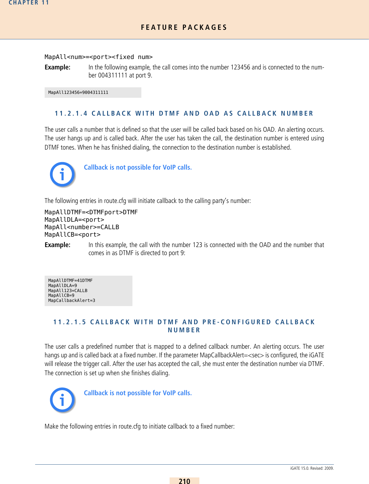
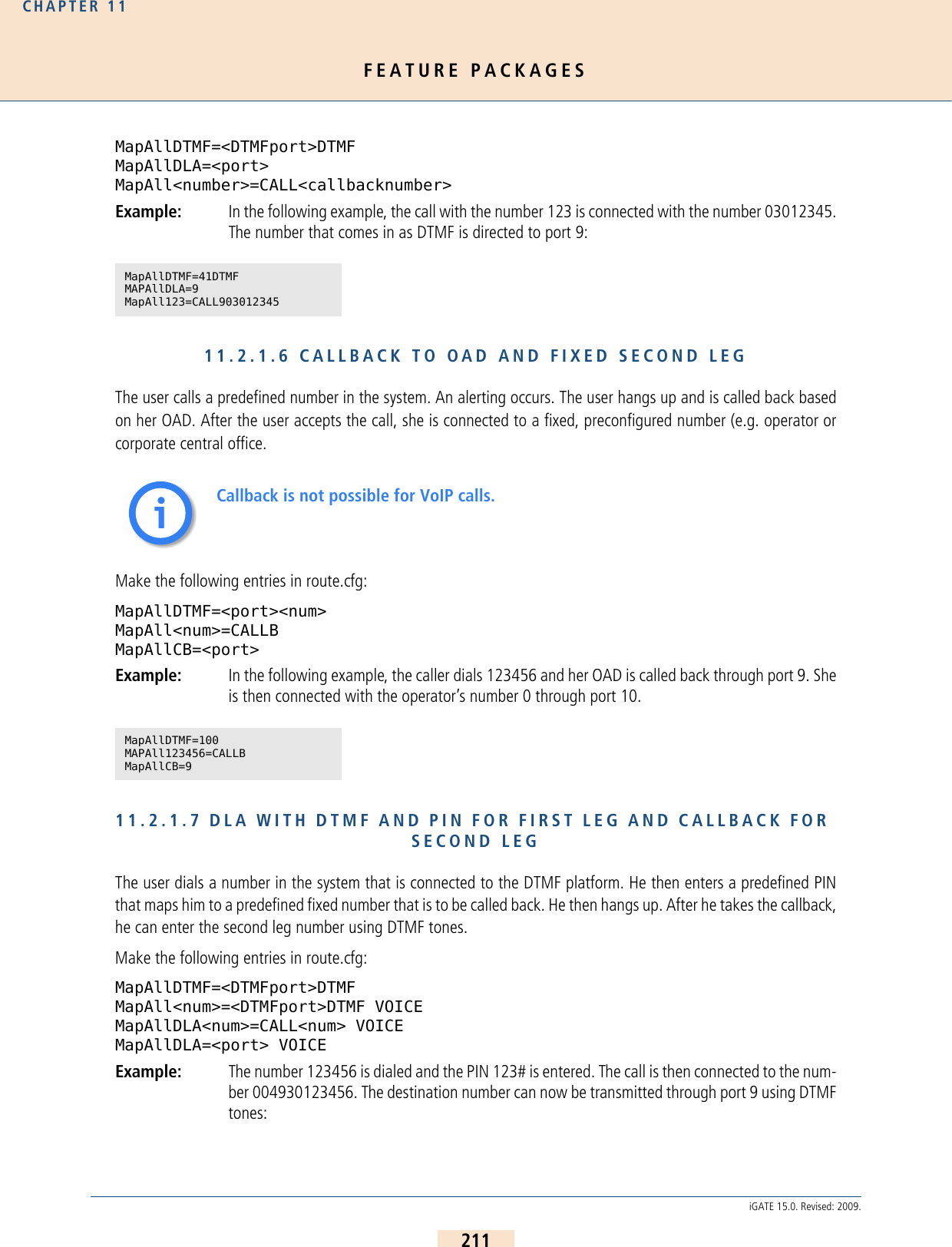
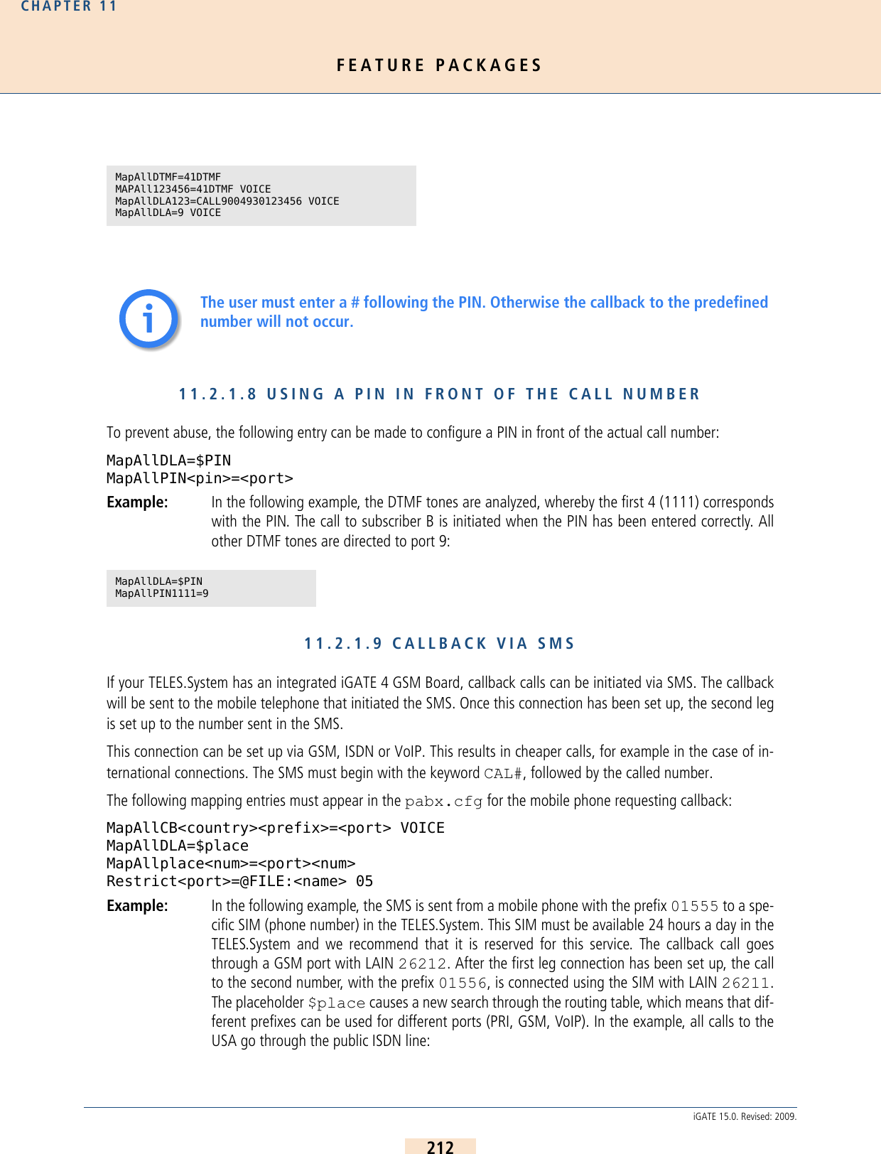
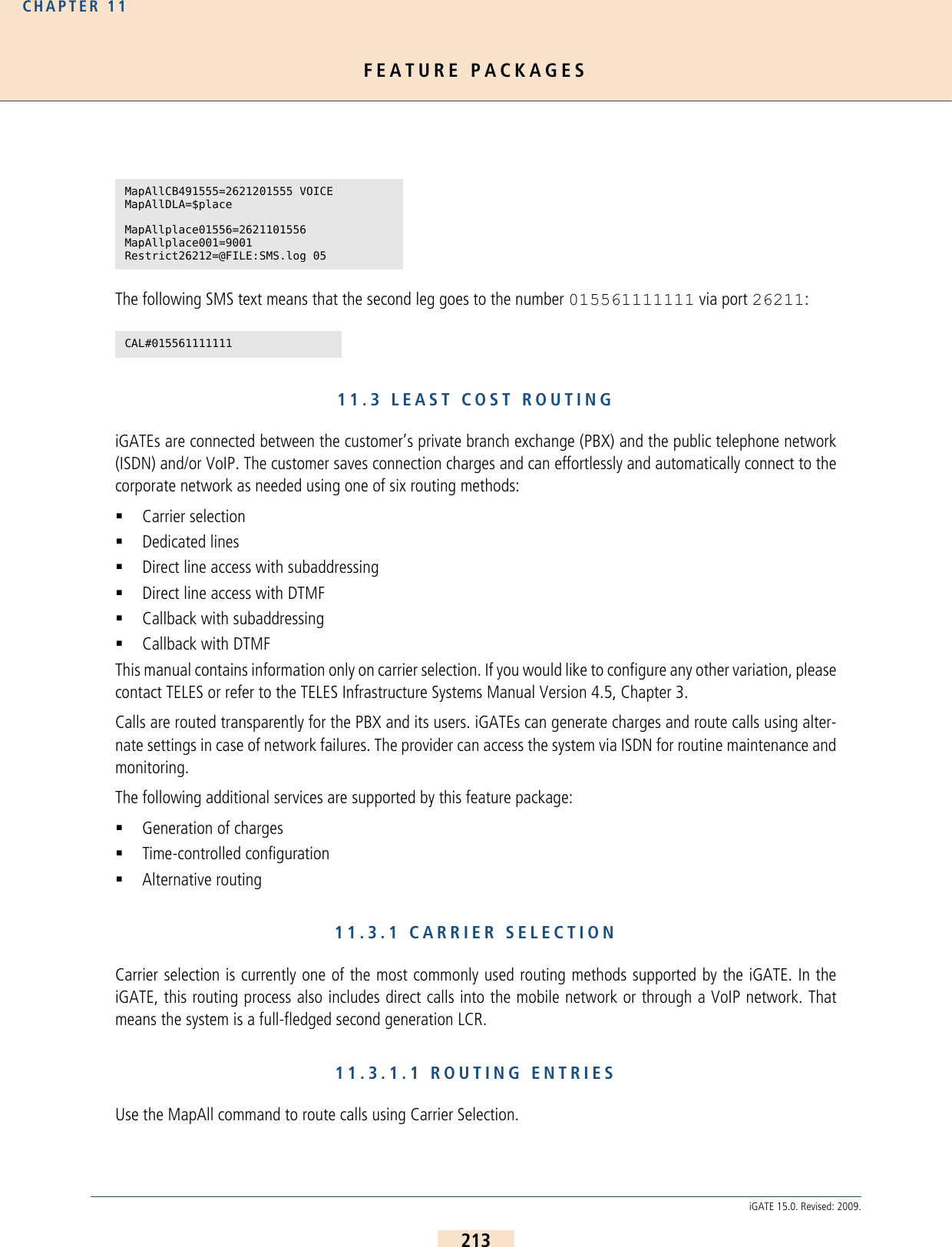
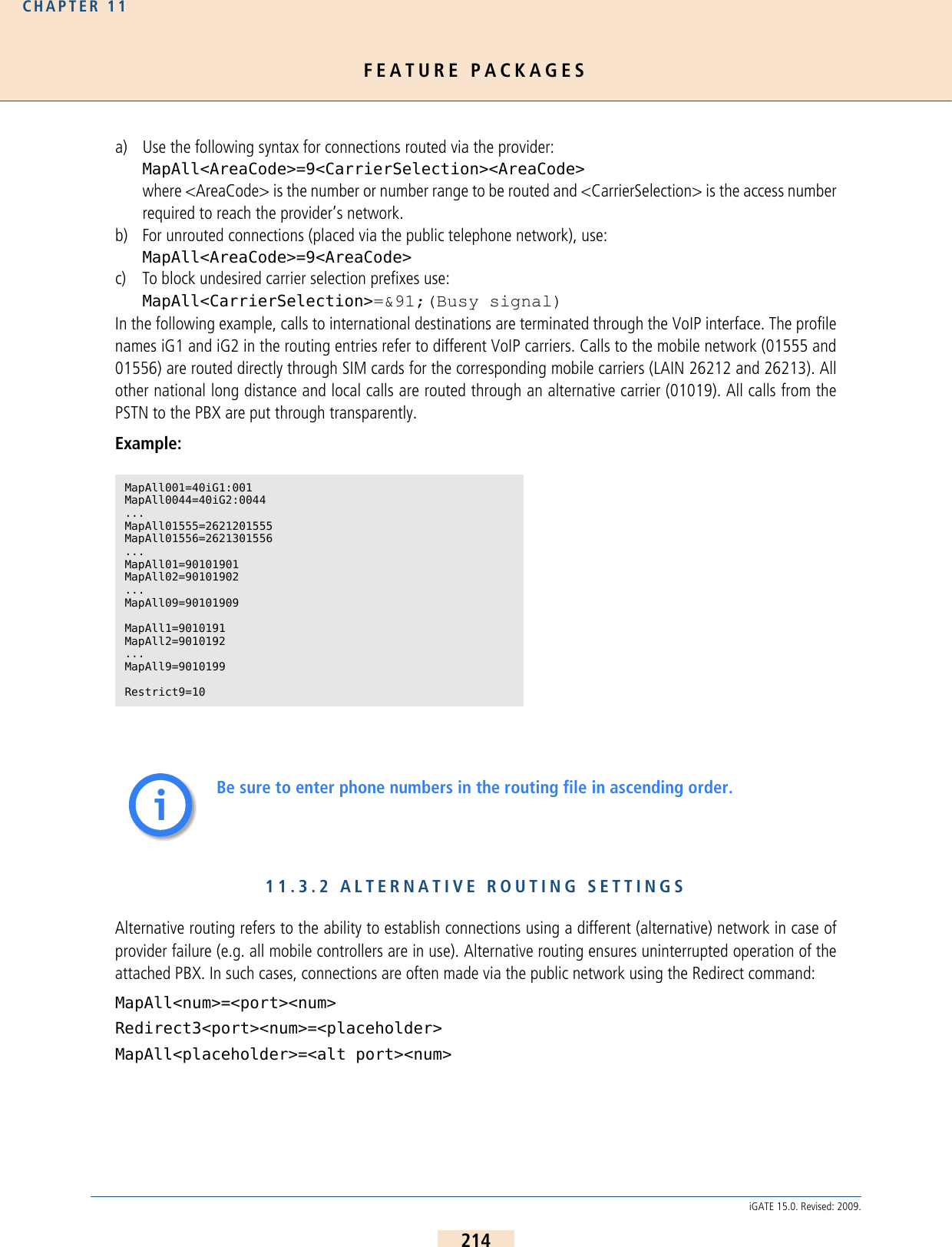
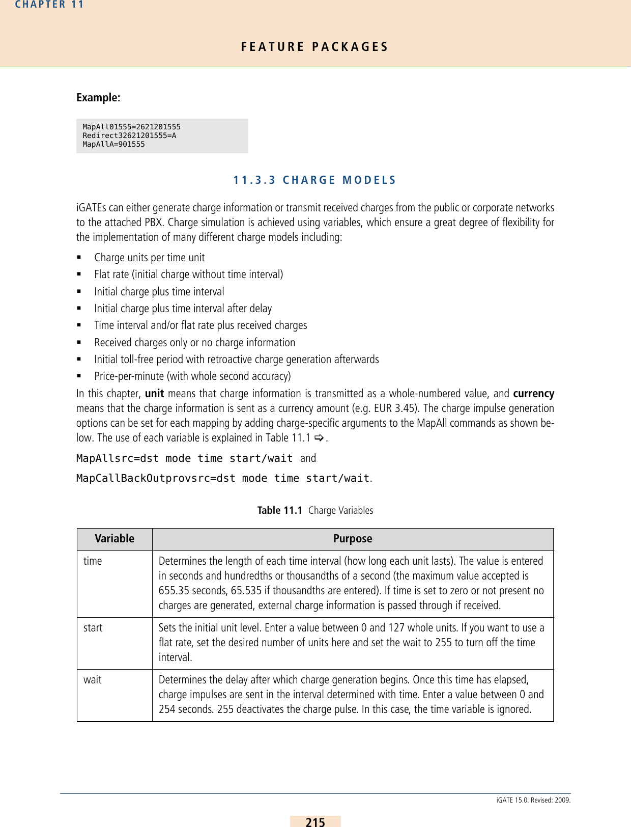
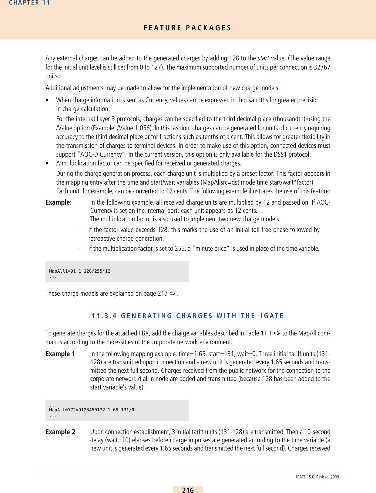
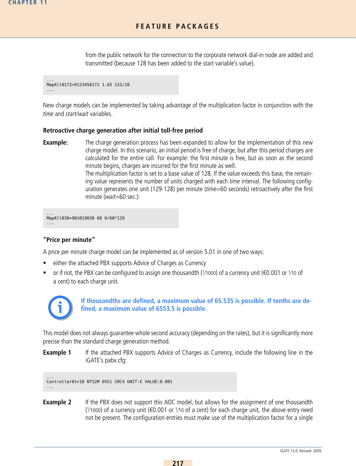
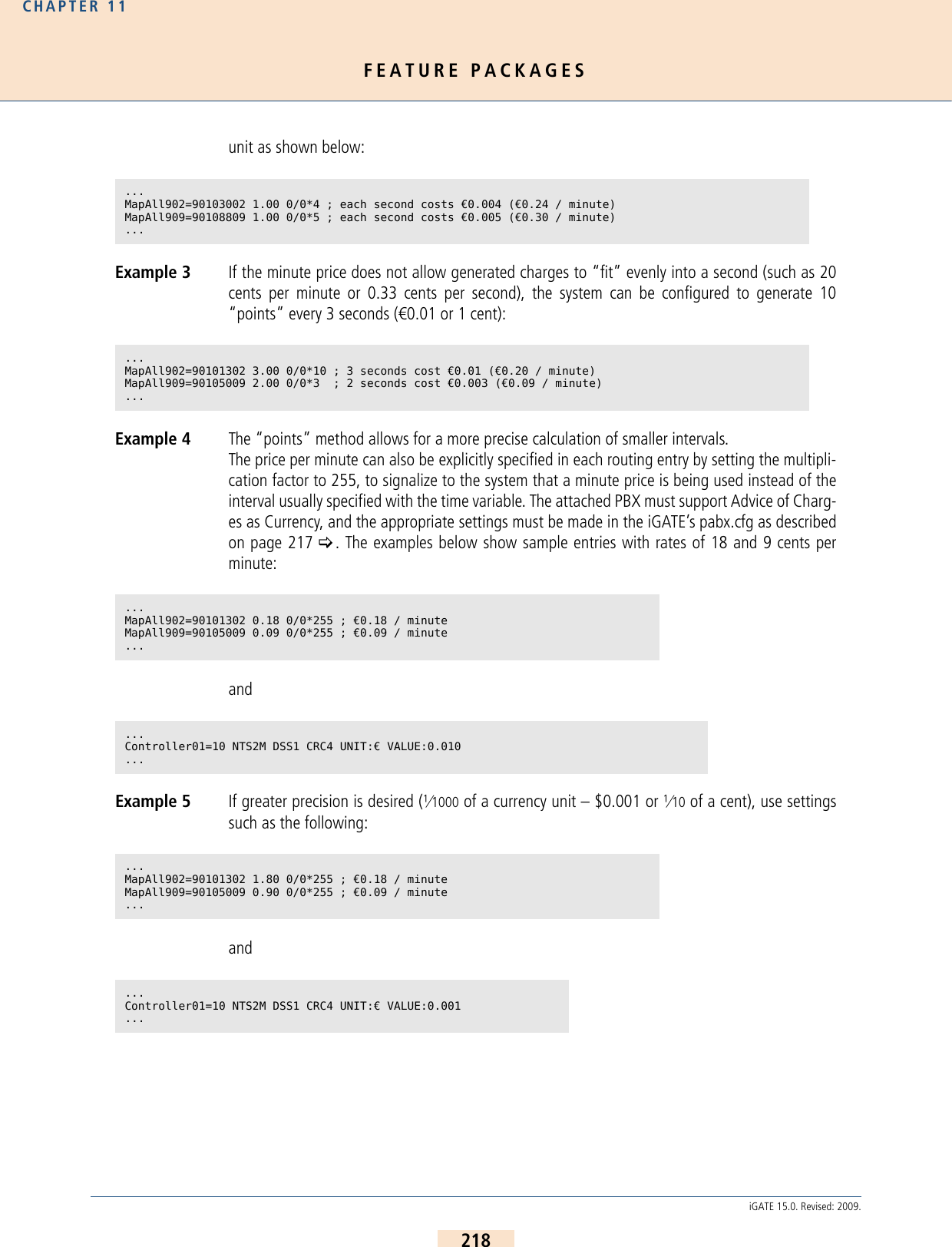
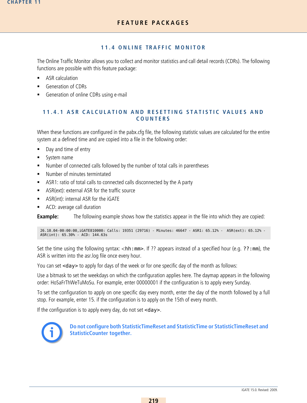
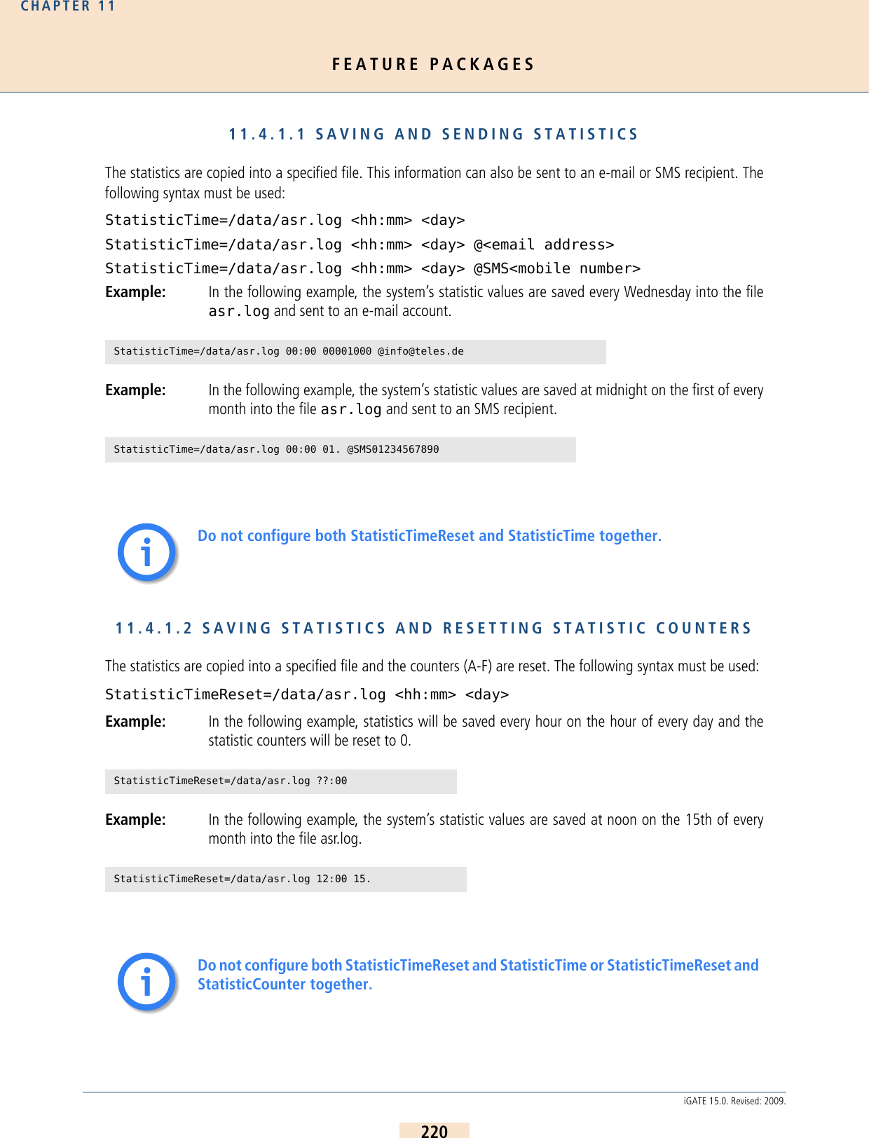
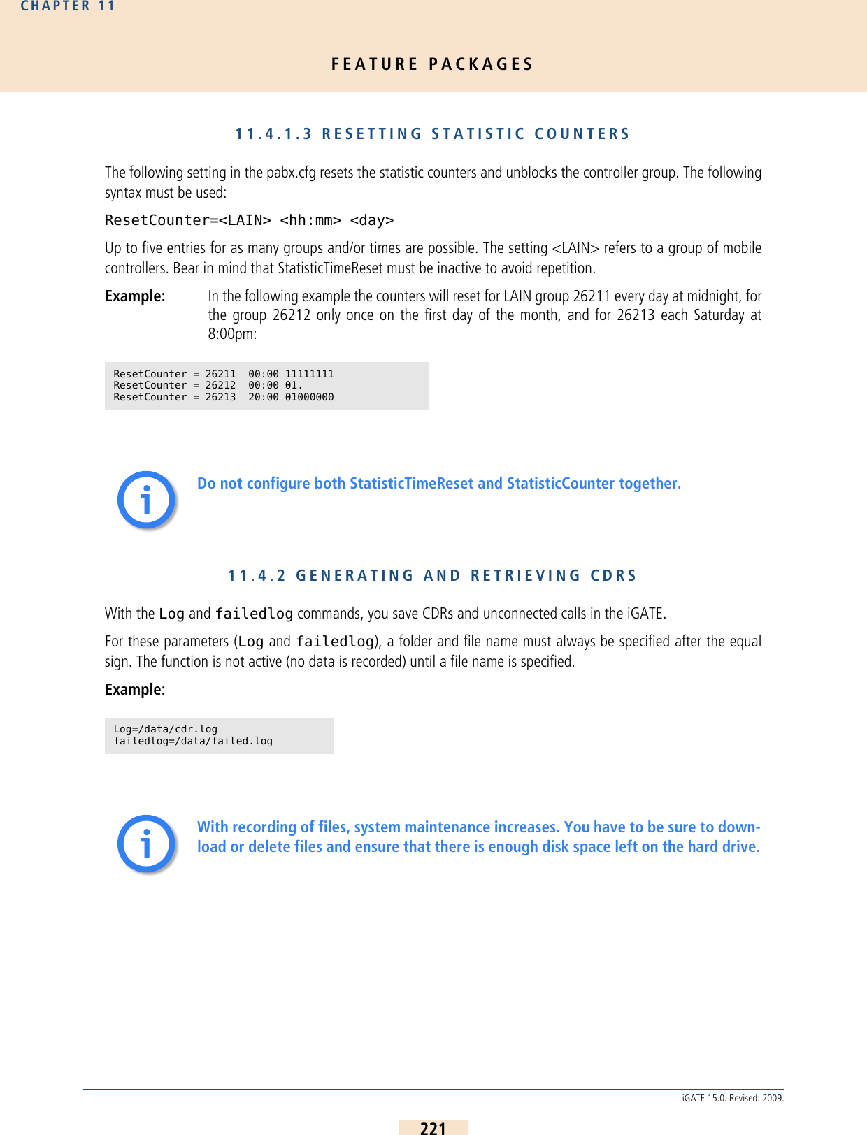
![FEATURE PACKAGESCHAPTER 11222iGATE 15.0. Revised: 2009.The service indicator listed in the call log and missed calls list describes the type of connection as a four digit hexa-decimal number. The coding is conducted according to the 1TR6 standard. A few frequently used values are listedbelow:0101 ISDN-telephony 3.1 kHz0102 analog telephony0103 ISDN-telephony 7 kHz0200 Fax group 20202 Fax group 30203 Data via modem0400 Telefax group 40500 SMS or BTX (64 kbps)0700 Data transfer 64 kbps07… Bit rate adaptation1001 Video telephone – audio 3.1 kHz1002 Video telephone – audio 7 kHz1003 Video telephone – videoFor detailed information on how to automatically divide the files (e.g. on a daily basis), please refer to theChapter 5.2.1.2 >.11.4.2.1 CALL LOGThe following entry in the pabx.cfg configuration file activates the capability to generate CDRs in the iGATE:Log=/data/cdr.logThe cdr.log file is stored in the data directory. New entries are always added to the end of the file. The file is openonly during editing. Each line represents an outgoing call with the following information separated by commas:Table 11.2 Call Log Entries Column Description0Version1Start time (format DD.MM.YY-hh.mm.ss)2End time (format DD.MM.YY-hh.mm.ss)3Source. The following format applies: [node number:automatically set internal channel number]4Destination. The following format applies: [node number:automatically set internal chan-nel number]5IMSI](https://usermanual.wiki/Teles-Informationstechnologien/GSM32VOIPUS/User-Guide-1224551-Page-222.png)
![FEATURE PACKAGESCHAPTER 11223iGATE 15.0. Revised: 2009.Sample Log FileThe example below shows a sample log file: Differentiating Between Ports in the Same Trunk GroupTo differentiate between ports with the same number in the CDRs, a specific node number must be defined. Youcan expand the subscriber configuration line with the keyword NODE[<no.>] for this purpose. <no.> can be astring of between 1 and 15 characters:Subscriber<xx>=... NODE[<num>]Example:In the above formula, <num> consists of a four-digit number that is included in the CDR. 6IP logging signaling: RTP7Audio codec used8Frame size9Service indicator (cf. Chapter 11.4.2 on page 221 >)10 Call duration11 Cause values12 Charge from the public line (in units)13 Charge generated from the system (in units)14 Cell ID15 RSSIV1,25.11.09-10:16:20,25.11.09-10:16:27,[0000:01]9,[0006:01]111,123456789123451,,,,0102,7,1f,0,,3663,10V1,25.11.09-10:35:16,25.11.09-10:35:26,[0000:01]9,[0004:01]111,123456789123452,,,,0102,10,1f,0,3,38922,14V1,25.11.09-10:38:30,25.11.09-10:38:41,[0000:01]9,[0004:01]111,123456789123453,,,,0102,11,90,0,3,38922,14V1,25.11.09-10:16:20,25.11.09-10:16:27,[0000:01]9,[0006:01]111,123456789123451,,,,0102,7,1f,0,,3663,10Table 11.2 Call Log Entries (continued)Column Description](https://usermanual.wiki/Teles-Informationstechnologien/GSM32VOIPUS/User-Guide-1224551-Page-223.png)
![FEATURE PACKAGESCHAPTER 11224iGATE 15.0. Revised: 2009.Example: The following example shows the pabx.cfg configuration file changed according to the formula:Differentiating Between SIM CardsThe CDR can contain the IMSI (International Mobile Subscriber Identity), which identifies each SIM card used:Example:The following example shows the pabx.cfg configuration file changed according to the formula:Example:Activating Peer Data for VoIP CallsTo generate a VoIP-call CDR entry that includes IP addresses for the remote device’s signaling and voice data, audiocodec and frame size, the entry VoipIpLogging=Yes must be included in the VoIP profile. If the entry alsocontains the mobile controller’s IMSI, it will appear before the IP addresses....Subscriber00=TRANSPARENT ROUTER GSM[0000,00000,<SMSC>,1,1,1,SIM24] CHADDR ALARM NEXT NODE[0001]Subscriber01=TRANSPARENT ROUTER GSM[0000,00000,<SMSC>,1,1,1,SIM24] CHADDR ALARM NEXT NODE[0002]Subscriber02=TRANSPARENT ROUTER GSM[0000,00000,<SMSC>,1,1,1,SIM24] CHADDR ALARM NEXT NODE[0003]Subscriber03=TRANSPARENT ROUTER GSM[0000,00000,<SMSC>,1,1,1,SIM24] CHADDR ALARM NEXT NODE[0004]Subscriber04=TRANSPARENT ROUTER GSM[0000,00000,<SMSC>,1,1,1,SIM24] CHADDR ALARM NEXT NODE[0005]Subscriber05=TRANSPARENT ROUTER GSM[0000,00000,<SMSC>,1,1,1,SIM24] CHADDR ALARM NEXT NODE[0006]Subscriber06=TRANSPARENT ROUTER GSM[0000,00000,<SMSC>,1,1,1,SIM24] CHADDR ALARM NEXT NODE[0007]Subscriber07=TRANSPARENT ROUTER GSM[0000,00000,<SMSC>,1,1,1,SIM24] CHADDR ALARM NEXT NODE[0008]Subscriber08=TRANSPARENT ROUTER GSM[0000,00000,<SMSC>,1,1,1,SIM24] CHADDR ALARM NEXT NODE[0009]Subscriber09=TRANSPARENT ROUTER GSM[0000,00000,<SMSC>,1,1,1,SIM24] CHADDR ALARM NEXT NODE[0010]Subscriber10=TRANSPARENT ROUTER GSM[0000,00000,<SMSC>,1,1,1,SIM24] CHADDR ALARM NEXT NODE[0011]Subscriber11=TRANSPARENT ROUTER GSM[0000,00000,<SMSC>,1,1,1,SIM24] CHADDR ALARM NEXT NODE[0012]Subscriber12=TRANSPARENT ROUTER GSM[0000,00000,<SMSC>,1,1,1,SIM24] CHADDR ALARM NEXT NODE[0013]Subscriber13=TRANSPARENT ROUTER GSM[0000,00000,<SMSC>,1,1,1,SIM24] CHADDR ALARM NEXT NODE[0014]Subscriber14=TRANSPARENT ROUTER GSM[0000,00000,<SMSC>,1,1,1,SIM24] CHADDR ALARM NEXT NODE[0015]Subscriber15=TRANSPARENT ROUTER GSM[0000,00000,<SMSC>,1,1,1,SIM24] CHADDR ALARM NEXT NODE[0016]...V1,25.11.09-10:35:16,25.11.09-10:35:26,[0000:01]9,[0004:01]111,123456789123451,,,,0102,10,1f,0,3,38922,14...Subscriber00=TRANSPARENT ROUTER GSM[0000,00000,<SMSC>,1,1,1,IMSI,SIM24] CHADDR ALARM NEXTSubscriber01=TRANSPARENT ROUTER GSM[0000,00000,<SMSC>,1,1,1,IMSI,SIM24] CHADDR ALARM NEXTSubscriber02=TRANSPARENT ROUTER GSM[0000,00000,<SMSC>,1,1,1,IMSI,SIM24] CHADDR ALARM NEXTSubscriber03=TRANSPARENT ROUTER GSM[0000,00000,<SMSC>,1,1,1,IMSI,SIM24] CHADDR ALARM NEXTSubscriber04=TRANSPARENT ROUTER GSM[0000,00000,<SMSC>,1,1,1,IMSI,SIM24] CHADDR ALARM NEXTSubscriber05=TRANSPARENT ROUTER GSM[0000,00000,<SMSC>,1,1,1,IMSI,SIM24] CHADDR ALARM NEXTSubscriber06=TRANSPARENT ROUTER GSM[0000,00000,<SMSC>,1,1,1,IMSI,SIM24] CHADDR ALARM NEXTSubscriber07=TRANSPARENT ROUTER GSM[0000,00000,<SMSC>,1,1,1,IMSI,SIM24] CHADDR ALARM NEXTSubscriber08=TRANSPARENT ROUTER GSM[0000,00000,<SMSC>,1,1,1,IMSI,SIM24] CHADDR ALARM NEXTSubscriber09=TRANSPARENT ROUTER GSM[0000,00000,<SMSC>,1,1,1,IMSI,SIM24] CHADDR ALARM NEXTSubscriber10=TRANSPARENT ROUTER GSM[0000,00000,<SMSC>,1,1,1,IMSI,SIM24] CHADDR ALARM NEXTSubscriber11=TRANSPARENT ROUTER GSM[0000,00000,<SMSC>,1,1,1,IMSI,SIM24] CHADDR ALARM NEXTSubscriber12=TRANSPARENT ROUTER GSM[0000,00000,<SMSC>,1,1,1,IMSI,SIM24] CHADDR ALARM NEXTSubscriber13=TRANSPARENT ROUTER GSM[0000,00000,<SMSC>,1,1,1,IMSI,SIM24] CHADDR ALARM NEXTSubscriber14=TRANSPARENT ROUTER GSM[0000,00000,<SMSC>,1,1,1,IMSI,SIM24] CHADDR ALARM NEXT...If you remove the keyword IMSI from the pabx.cfg, you must restart the system.ii](https://usermanual.wiki/Teles-Informationstechnologien/GSM32VOIPUS/User-Guide-1224551-Page-224.png)
![FEATURE PACKAGESCHAPTER 11225iGATE 15.0. Revised: 2009.The following entry shows the route.cfg configuration file changed according to the formula:Example: The following CDR entry includes IP addresses for signaling and voice data, audio codec andframe size. CDRs for Callback and Two-Stage CallsIn the case of CDR entries for DLA/Callback calls, the beginning and ending times for the first call leg is alwaysused as the call time. The call time in seconds appears first for the first leg, followed by a slash and the connectiontime for the second leg.Example:Specific Cause ValuesThe iGATE will generate cause values that represent an event, such as exceeding a defined limit:11.4.2.2 MISSED CALLS LISTAll incoming calls that are not connected can be recorded in a list to facilitate return calls. Recording is activatedusing the failedlog=<name> entry in the pabx.cfg. Specify a file name, e.g. failedlog=failed.log. Once this settingis made, recording begins at once.[Voip:DF]VoipDirection=IOVoipPeerAddress=192.168.0.2VoipIpMask=0xffffffffVoipCompression=g729 t38VoipMaxChan=30VoipSilenceSuppression=Yes VoipSignalling=0VoipTxM=4VoipIPLogging=YesV1,24.11.09-16:52:20,24.11.09-16:52:22,[0008:01]401419,[0006:01]IN777,123456789123451,172.20.25.103:172.20.25.103,G711a,20,0101,2,10,0,,34193,11V1,24.11.09-17:15:29,24.11.09-17:15:57,[0002:01]CB,[0008:01]DLA,,172.20.25.103:172.20.25.103,G711a,20,0102,28/3,90,0,,,0a One of the following limits has been reached: Unit limit defined in the port’s subscriber lineUnit limit per SIM assignment via vGATE 0b Maximum call duration assigned via vGATE has been reached0c Maximum call duration based on mapping entry settings has been reached0d Maximum number of minutes per SIM assignment via vGATE has been reached10, 1f Normal call termination (disconnected by calling party)To avoid sending these values as the reason for call teardown, translate the cause values to standard values Chapter 8.12 >ii](https://usermanual.wiki/Teles-Informationstechnologien/GSM32VOIPUS/User-Guide-1224551-Page-225.png)
![FEATURE PACKAGESCHAPTER 11226iGATE 15.0. Revised: 2009.Each line represents an unaccepted incoming call with the following information separated by commas:Sample Failed LogThe example below shows a sample failed log file:The reason the connection could not be established is specified using DSS1 codes:91 – (user busy)ff – call not answered (disconnected by calling party)Table 11.3 Failed Log Entries Column Description0Version1Start time (format DD.MM.YY-hh.mm.ss)2Source. The following format applies: [node number:automatically set internal channel number]3Destination. The following format applies: [node number:automatically set internal chan-nel number]4IMSI5IP logging signaling: RTP6Audio codec used7Frame size8Service indicator (cf. Chapter 11.4.2 on page 221 >)9Cause values10 Call duration (if the call does not result in an Alerting, the entry will be -1)11 Number of call attempts12 Cell ID13 RSSIV1,24.11.09-16:13:08,[0006:01]IN,[0008:01]GSM,123456789123456,,,,0101,92,-1,1,34193,9V1,24.11.09-16:33:34,[0006:01]IN,[0008:01]GSM,123456789123456,,,,0101,92,-1,1,34193,12V1,24.11.09-16:35:19,[0006:01]IN,[0008:01]GSM,123456789123456,,,,0101,92,-1,1,34193,11V1,24.11.09-16:35:59,[0006:01]IN,[0008:01]GSM,123456789123456,,,,0101,92,-1,1,34193,11V1,24.11.09-16:37:29,[0006:01]IN,[0008:01]GSM,123456789123456,,,,0101,92,-1,1,34193,11V1,24.11.09-16:39:17,[0006:01]IN,[0008:01]GSM,123456789123456,,,,0101,ff,7,1,34193,11](https://usermanual.wiki/Teles-Informationstechnologien/GSM32VOIPUS/User-Guide-1224551-Page-226.png)
![FEATURE PACKAGESCHAPTER 11227iGATE 15.0. Revised: 2009.When callback with DTMF is configured and no connection is established to the B subscriber, an entry recordingthe A subscriber’s connection time is generated in the failed.log file:The CDR contains the IP addresses for signaling and voice data. The first IP address is the signaling address andthe second one is the RTP address.The IMSI is written behind the IP addresses if the keyword IMSI is defined in thepabx.cfg:Example:In the case of missed-call entries for DLA/Callback calls, dur is the connection time for the first leg.Example:11.4.2.3 SENDING CDRS VIA E-MAILWith an appropriate configuration, you can send corresponding CDRs of outgoing and incoming calls as e-mail.Bear in mind that the mail server must be configured in the [Mail] section of the pabx.cfg, as described inChapter 5.2.2 >. The sender is given as cdr and the system’s name appears in the subject box. The text box con-tains the CDR information according to the format for the entry in Log=/data/cdr.log @<account> @<domain>.A space must appear between cdr.log and @<account>; @<domain> is optional. You can also send CDR entriesvia e-mail to an e-mail recipient. Enter an @ sign to send each CDR entry as e-mail: Log=/data/cdr.log @<e-mail account>@<domain>If you enter a ! the entire cdr.log will be sent as an e-mail attachment:Log=/data/cdr.log !<e-mail account>@<domain>V1,24.11.09-16:39:17,[0006:01]IN,[0008:01]GSM,123456789123456,,,,0101,ff,7,1,34193,11V1,24.11.09-16:52:20,24.11.09-16:52:22,[0008:01]401419,[0006:01]IN777,262032441017556,172.20.25.103:172.20.25.103,G711a,20,0101,2,10,0,,34193,11V1,25.11.09-14:11:10,[0002:01]CB,DLA,,,,,0102,11,14,1,,](https://usermanual.wiki/Teles-Informationstechnologien/GSM32VOIPUS/User-Guide-1224551-Page-227.png)
![FEATURE PACKAGESCHAPTER 11228iGATE 15.0. Revised: 2009.11.5 SMS GATEWAYThe SMS Gateway allows you to use your iGATE to send and receive SMS. The following functions are possible withthis feature package:Sending SMS via e-mailReceiving SMS to e-mail, SMS or to a fileSending and receiving USSD text messagesSetting up connections using e-mailSending automatic SMS for unconnected calls11.5.1 SENDING SMS VIA E-MAIL This function makes it possible to send SMS via a iGATE with an ordinary e-mail client. SMS messages are recordedin the CDR log with the service indicator 0500. The destination address with the keyword SMS, the call number,the @ sign and the IP address or the IP name of the iGATE must be entered.In the following example, an SMS is sent to the mobile number 015553456789, whereby sms-mail.server.de mustcorrespond with the IP address 172.172.172.172:Example: SMS015553456789@172.172.172.172 orSMS015553456789@sms-mail.server.deThe SMS text must be entered in the text box. The subject box is not used. If the e-mail program supports sendingthe same e-mail to more than one address, the SMS messages are sent in intervals of one second. The iGATE’salgorithms evenly distribute the SMS messages to the available mobile modules.If the iGATE rejects the SMS, an e-mail alerting an aborted SMS will be transmitted to the sender and the attemptwill be entered in the corresponding log file (failedlog=). If transmission is successful, a positive response will besent when the SMS is accepted by the SMS service center. sent will then appear in the subject dialog. A correspond-ing CDR will be entered with a destination address beginning with SMS.A request to set up a connection with the service ’telephony’ and the element ’user-to-user’ enables the SMS textto be sent to the iGATE. All iGATEs are supported that allow for SMS messages to be sent by the process describedabove. According to the restrictions of the ISDN signaling protocol, text length is limited to approximately 110-120characters. Longer texts will be cut off accordingly.The following entry must appear in the route.cfg configuration file for SMS transmission to be possible: Ma-pAllSMS=<port number>.Bear in mind that the parameters for connection to the SMTP server must be config-ured in the pabx.cfg’s [Mail] section (cf. 5.2.2 on page 77 >).To use this function, you must first set the parameter <smsc> in the pabx.cfg (cf. Table 5.15 on page 68 >).iiii](https://usermanual.wiki/Teles-Informationstechnologien/GSM32VOIPUS/User-Guide-1224551-Page-228.png)
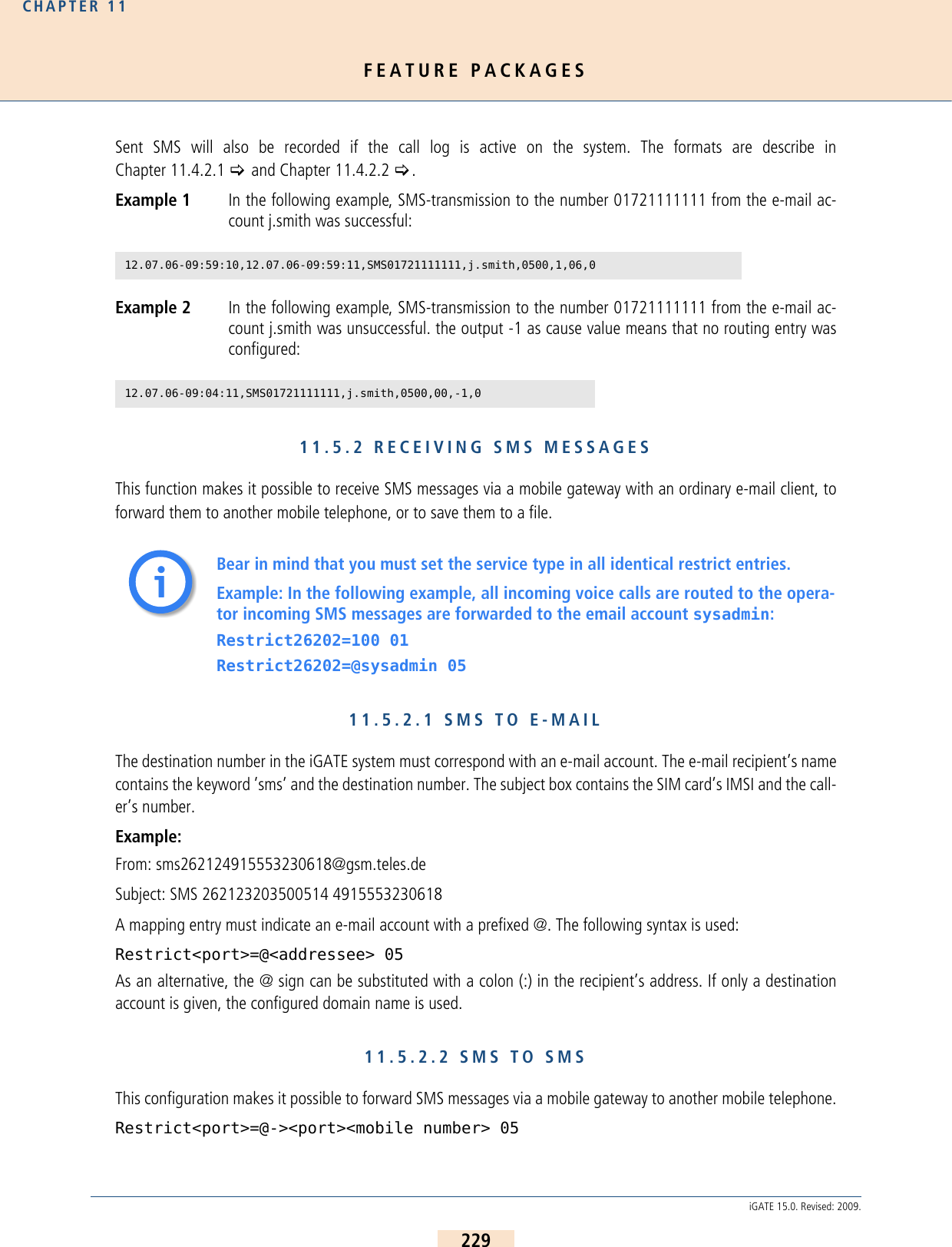
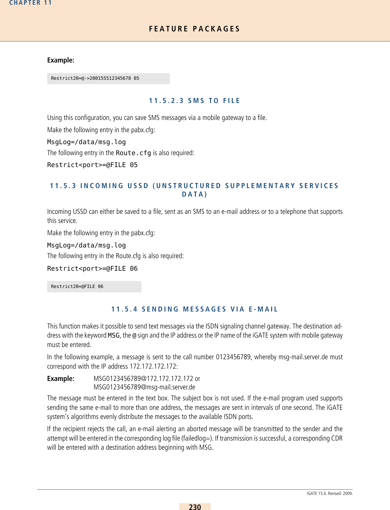
![FEATURE PACKAGESCHAPTER 11231iGATE 15.0. Revised: 2009.A request to set up a connection with the service ’telephony’ and the element ’user-to-user’ enables the messageto be sent to the recipient. All terminal devices and PBXes are supported that allow for messages to be sent by theprocess described above. According to the restrictions of the ISDN signaling protocol, text length is limited to ap-proximately 110-120 characters. Longer texts will be cut off accordingly.11.5.5 SETTING UP CONNECTIONS VIA E-MAILThis function sets up a connection between subscriber A and subscriber B via e-mail. Subscriber A is identified byan e-mail address and is dialed first. Subscriber B is called when the connection to subscriber A has been set up. A connection can be set up via e-mail with the keyword ’CALL,’ the destination number, the @ sign, and the IPaddress or the iGATE system’s IP name.The following example shows a connection with the destination number 0123456789, whereby msg-mail.serv-er.de must correspond with the IP address 172.172.172.172.Example: CALL0123456789@172.172.172.172 orCALL0123456789@msg-mail.server.deAny text contained in the text box will be sent to subscriber A as user-to-user information. The subject box is notused.Subscriber A is identified by an e-mail address and must be activated in the iGATE system. The subscriber’s namemust appear before the @ sign. This name must be assigned a corresponding MapOut command.Example: Subscriber’s e-mail address is meier@server.de. Subscriber’s extension is 555. Configure Ma-pAll@555=meier.In addition to CTI capability, this function allows for callback via e-mail.11.5.6 DISPLAYING INCOMING CALLSWith this function, you can use e-mail to signal incoming calls. Two signaling types are possible:Display all incoming calls that receive a busy or ringing signal. Enter the keyword CTI[001.000.000.000]in the VoIP controller’s Subscriber line of the iGATE system’s pabx.cfg configuration file.Display all unsuccessful incoming calls (callback list) that receive a busy signal or remain unanswered.Enter the keyword CTI[002.000.000.000] in the VoIP controller’s subscriber line of the iGATE system’spabx.cfg configuration file.The destination is the address of the called subscriber configured in a corresponding map entry. A callback can beinitiated when the recipient responds to the e-mail.The following entry must appear in the route.cfg:MapAllMSG=<port>ii](https://usermanual.wiki/Teles-Informationstechnologien/GSM32VOIPUS/User-Guide-1224551-Page-231.png)
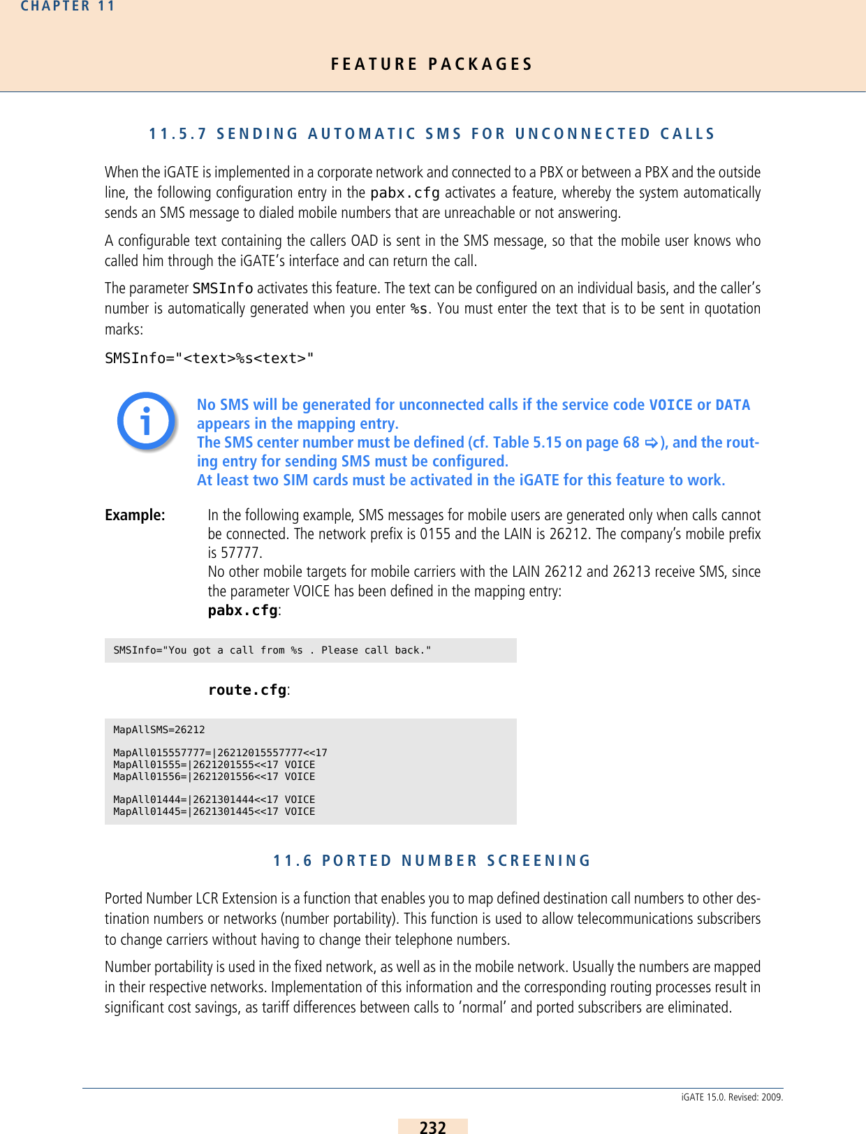
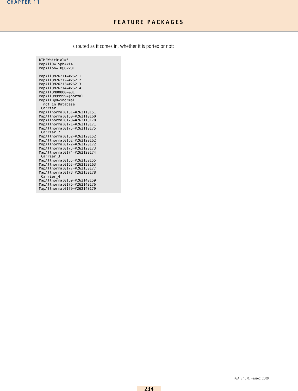
![OPTIONAL FUNCTION MODULESCHAPTER 12236iGATE 15.0. Revised: 2009.12.2 GRAPHICAL USER INTERFACEThe GUI is a user-friendly tool that can be used by carriers, administrators and individual users to configure theiGATE. For a detailed description of the GUI, please see Chapter 4.12.2 >12.3 SNMP AGENTThis module allows you to connect the systems and their functions to an SNMP-based network monitoring system.With this module, SNMP requests are answered and alarm messages (E.g. Layer 1 errors on E1 lines) and errorrecovery messages are sent via SNMP trap. Traps are generated for all line or mobile ports. The running number in the trap corresponds with the port. Themodule also monitors whether the voice codec chips are functioning correctly.The traps for the IP interfaces are also generated in ascending order according to the following list:If more than one pppoe<x> profile is configured, the number will also increase.Bear in mind that the keyword ALARM must be entered in the appropriate PRI, BRI or mobile port’s Subscriber linein the pabx.cfg. The MIBs (Management Information Bases) are included on the product CD in the folder MIB. Themodule name snmpd.tz0 must have the ending tz0!The following settings are possible in the section [snmpd]: Table 12.1 Traps for IP Interfaces Trap Number Interface0Ethernet 11Ethernet 22 Loopback3 xppp= (if used)4 pppoe= (if used)Table 12.2 Settings in the Section [snmpd]Parameter DefinitionPort=<port> Defines the target port for the trap server (default 161).TrapServer=<ip addr> Enter the SNMP trap server’s IP address. Example for listing more than one: TrapServer=192.168.0.10 192.168.0.12Community=<password> Enter a password for a community (group). The default password is public.](https://usermanual.wiki/Teles-Informationstechnologien/GSM32VOIPUS/User-Guide-1224551-Page-236.png)
![OPTIONAL FUNCTION MODULESCHAPTER 12238iGATE 15.0. Revised: 2009.Make the following entries in the system’s ip.cfg, in the [DynDNS] section: Example: In the following example, the DynDNS service is used and the domain name is host.domain.de;the username is user and the password is pwd. The iGATE works as DSL router and the dynami-cally allocated IP address of the PPPoE interface is used:Table 12.3 pabx.cfg: DynDNS DynDNS Parametersservice=<type>Specifies which provider is used. The following providers are supported:dhsdyndnsdyndns-staticdynsezipeasydnseasydns-partnergnudipheipv6tbhnpgpowodstzozoneedithttp://www.dhs.orghttp://www.dyndns.orghttp://www.dyns.cxhttp://www.ez-ip.nethttp:/www.easydns.comhttp://www.gnudip.cheapnet.nethttp://www.hn.orghttp:www.justlinux.comhttp://ods.orghttp://www.tzo.comhttp://zoneedit.comuser=<username:password>Defines the username and password for the DNS service provider.host=<domain_name_of_dns_service>Enter the domain name that is used.interface=<If>Defines the interface to be used. Possible entries are emac0, emac1, pppoe0. The dynamic IP address for this interface is transmitted to the service provider.max-interval=<sec>Defines the value in seconds in which actualization of the name in the DNS database must occur. 2073600 seconds (24 days) is the default value. The shortest interval allowed is 60 seconds. Bear in mind that this setting may cause the provider to block the domain name, since multiple registrations in short intervals are often not allowed. You must clear this with your provider.](https://usermanual.wiki/Teles-Informationstechnologien/GSM32VOIPUS/User-Guide-1224551-Page-238.png)
![OPTIONAL FUNCTION MODULESCHAPTER 12239iGATE 15.0. Revised: 2009.Included in the possible uses for this feature is remote access to the iGATE when the IP connection does not havea fixed IP address. In this case, you can access the system, for example with the GATE Manager, if the host nameis used in the Remote Number dialog. Example entry in the Remote Number dialog: IP:host.domain.de[DynDNS]service=dyndnsuser=user:pwdhost=host.domain.deinterface=pppoe0max-interval=2073600](https://usermanual.wiki/Teles-Informationstechnologien/GSM32VOIPUS/User-Guide-1224551-Page-239.png)