Teletronics TT900 TT Bridge Router User Manual IP3K Rev TT900
Teletronics International Inc TT Bridge Router IP3K Rev TT900
UserManual.wiki
>
Teletronics
>
TT900 User Manual
>
Professional installation User Manual
Contents
1.
Professional installation User Manual
2.
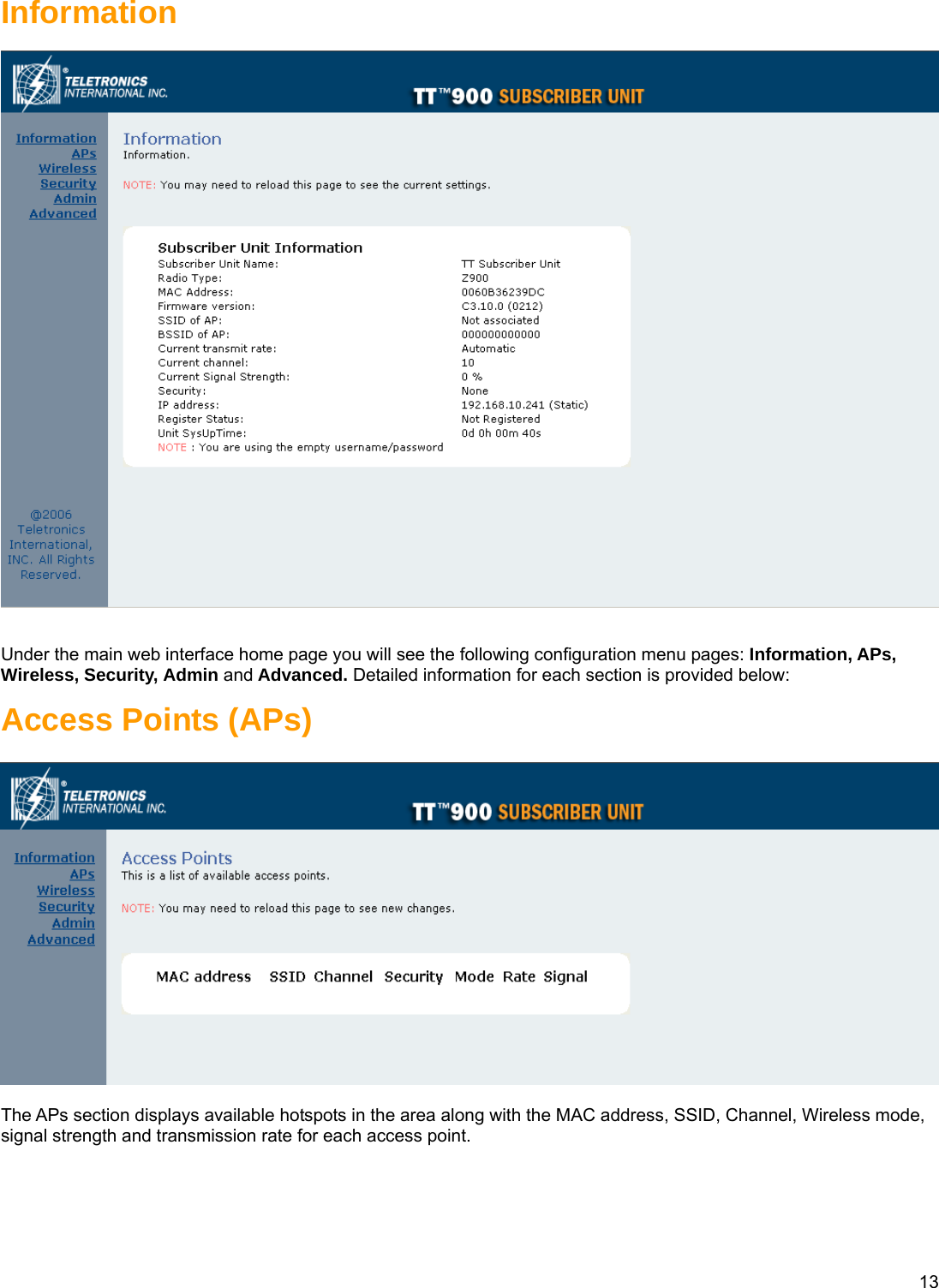
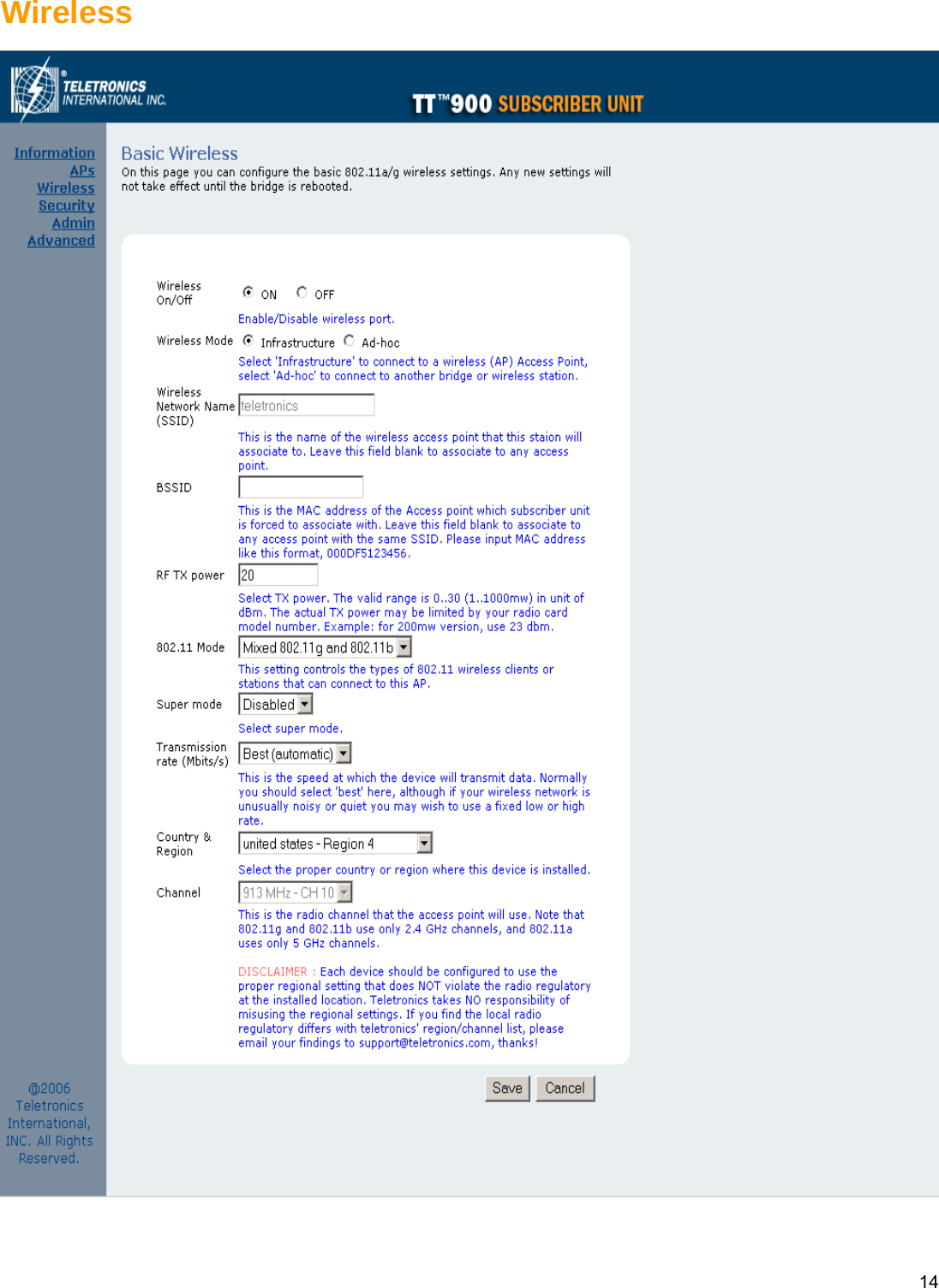
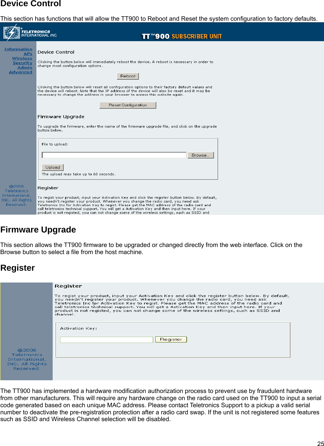
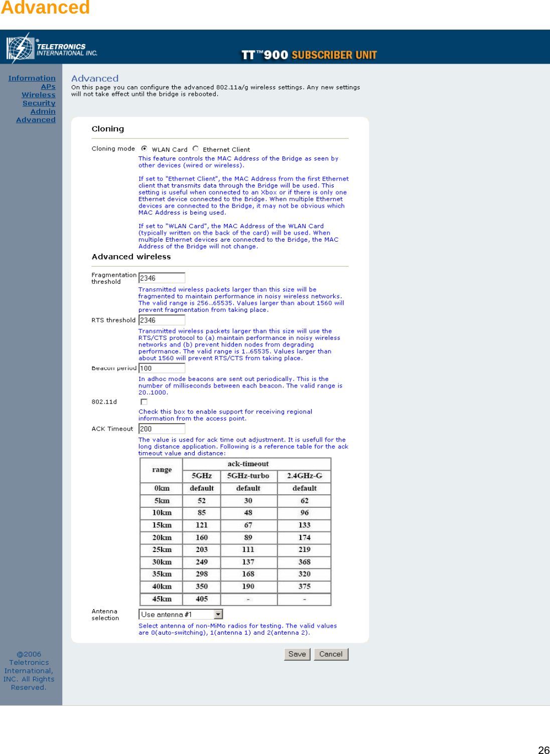
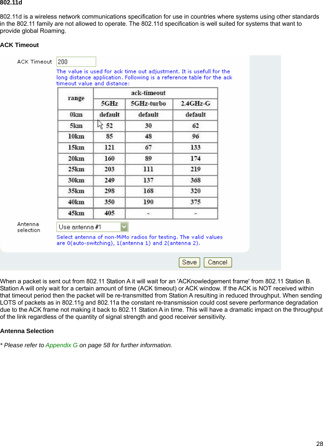
User Manual
Professional installation User Manual
Navigation menu
Upload a User Manual
Namespaces
Wiki Guide
HTML
PDF
Info
Views
User Manual
Discussion / Help
Navigation