Thrane and Thrane A S TU5160 Sailor System 5000 150W GMDSS MF/HF SSB DSC NBDP User Manual TT98 125586 0 PMD
Thrane & Thrane A/S Sailor System 5000 150W GMDSS MF/HF SSB DSC NBDP TT98 125586 0 PMD
UserManual.wiki
>
Thrane and Thrane A S
>
TU5160 User Manual
>
user manual 2
Contents
1.
user manual 1
2.
user manual 2
3.
user manual 3
4.
user manual 4
5.
user manual 5
6.
user manual 6
user manual 2
Navigation menu
Upload a User Manual
Namespaces
Wiki Guide
HTML
PDF
Info
Views
User Manual
Discussion / Help
Navigation

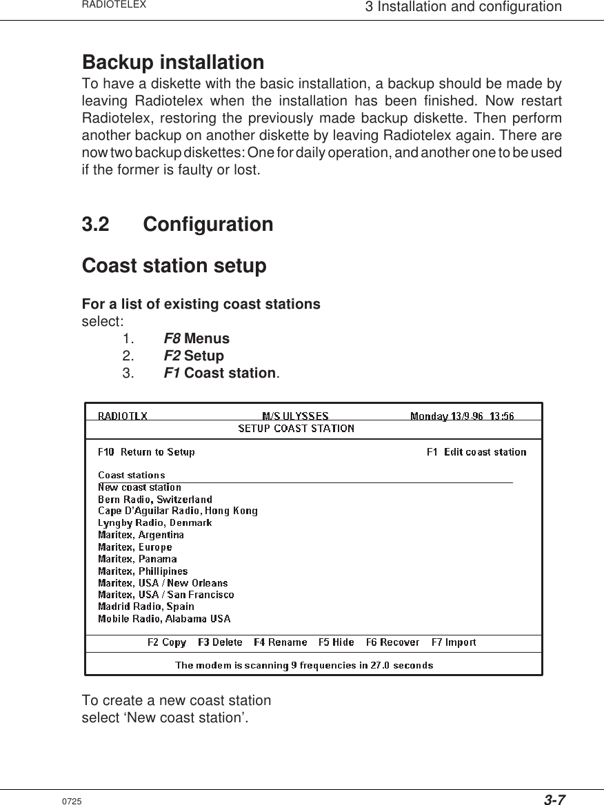
![3-2RADIOTELEX3 Installation and configurationInstallation on flash EPROM boardThe flash memory board is a non-volatile medium, which complies with theGMDSS requirements.The flash memory board facilitates installation. Insert the Radiotelex flashmemory installation diskette in the computer, and type:a: [b:] enterinstall enterAny software applications present on the flash memory board are nowdeleted, and the Radiotelex program is installed. This process may take up tofifteen minutes.Installation on hard diskNormally, the Radiotelex program is installed on a non-volatile medium, likethe flash memory board. A RAM disk is used for temporary storage, and it isnecessary to make backups.However, the Radiotelex program can also be installed on a hard disk. In that case,it is not necessary to make backups. Still, as a hard disk can crash, the non-volatileinstallation is necessary to comply with the requirements of the GMDSS.Thus, after the installation has been finished, it is advisable to make onebackup diskette, as described in this chapter. If it becomes necessary to usethe non-volatile installation (e.g. the flash memory board), this backupdiskette can be used when Radiotelex prompts to restore. This ensures thatthe basic installation is the same as when used on the hard disk.0725](https://usermanual.wiki/Thrane-and-Thrane-A-S/TU5160.user-manual-2/User-Guide-899714-Page-32.png)