Thrane and Thrane A S TU5160 Sailor System 5000 150W GMDSS MF/HF SSB DSC NBDP User Manual 98 124350 THR 0 pmd
Thrane & Thrane A/S Sailor System 5000 150W GMDSS MF/HF SSB DSC NBDP 98 124350 THR 0 pmd
UserManual.wiki
>
Thrane and Thrane A S
>
TU5160 User Manual
>
user manual 5
Contents
1.
user manual 1
2.
user manual 2
3.
user manual 3
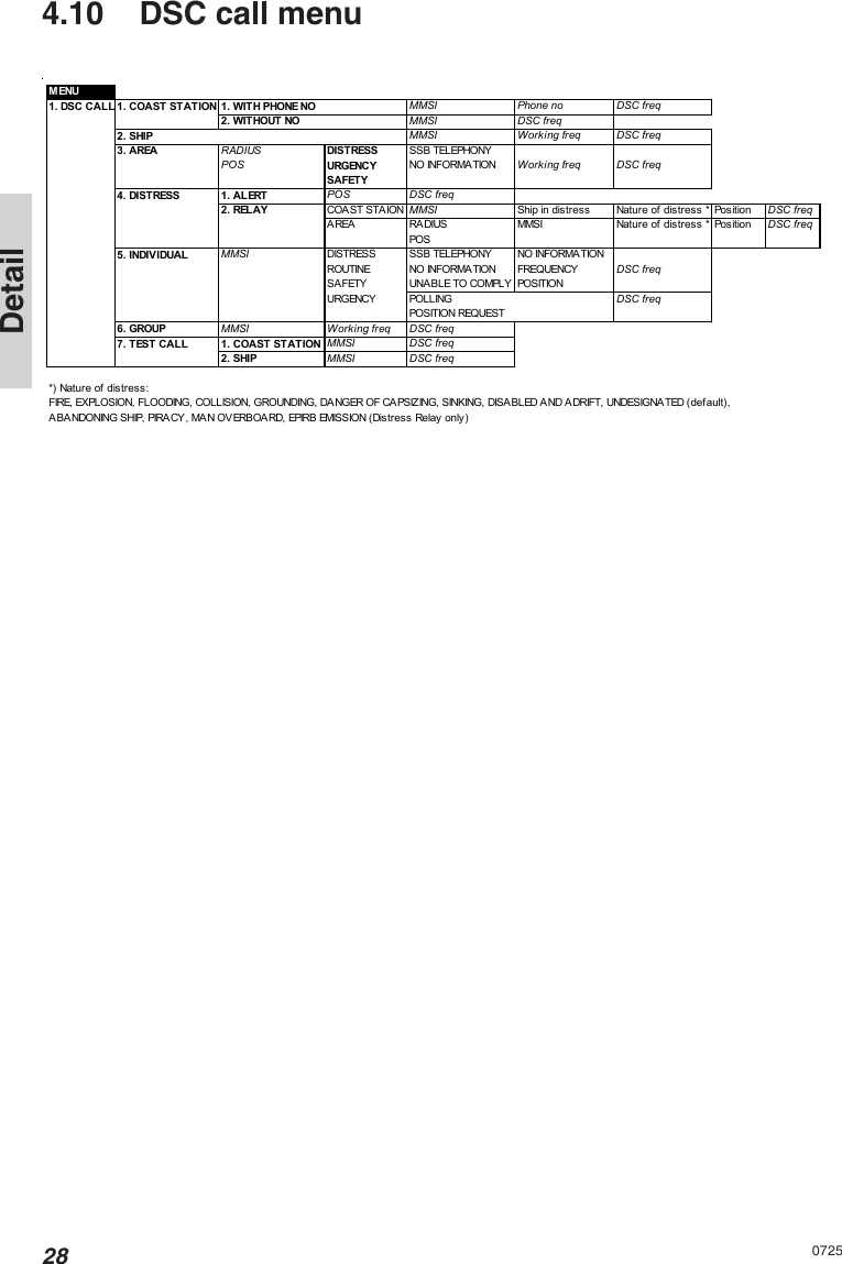
4.
user manual 4
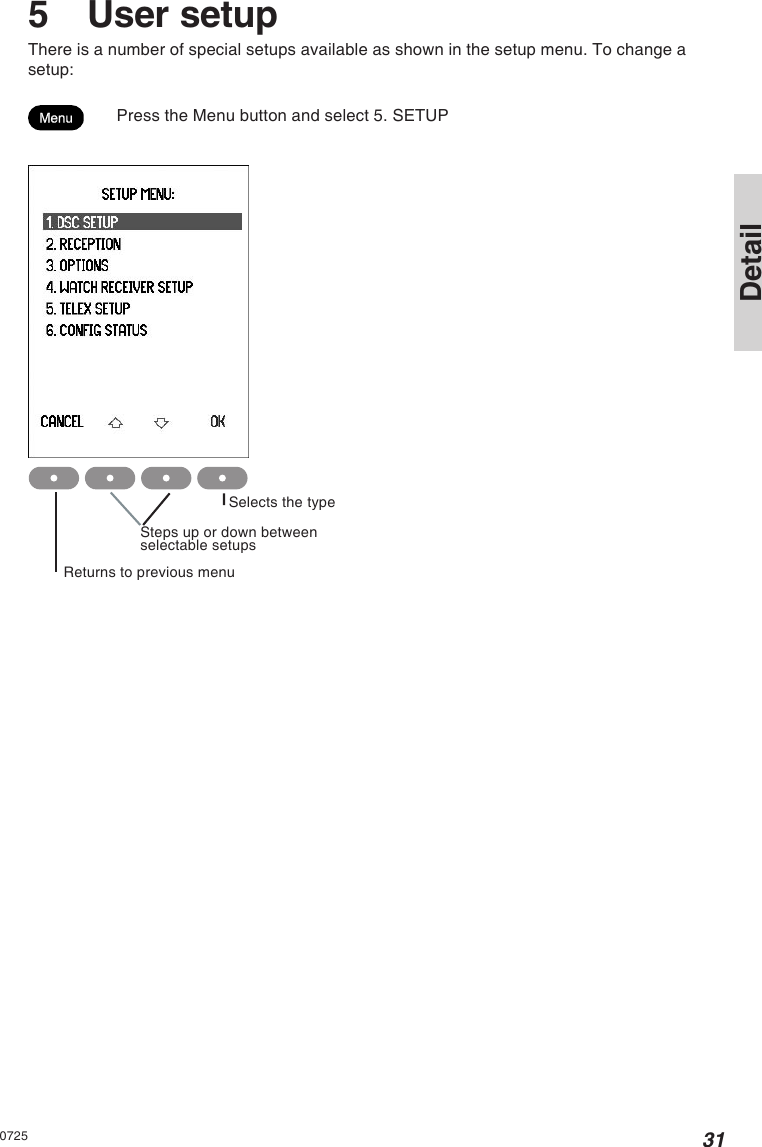
5.
user manual 5
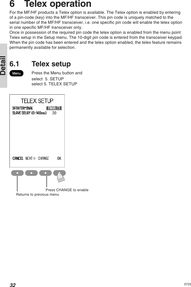
6.
user manual 6
user manual 5
Navigation menu
Upload a User Manual
Namespaces
Wiki Guide
HTML
PDF
Info
Views
User Manual
Discussion / Help
Navigation