Thrane and Thrane A S TU5160 Sailor System 5000 150W GMDSS MF/HF SSB DSC NBDP User Manual TT 3606E Installation Service Manual

Thrane & Thrane A/S Sailor System 5000 150W GMDSS MF/HF SSB DSC NBDP TT 3606E Installation Service Manual
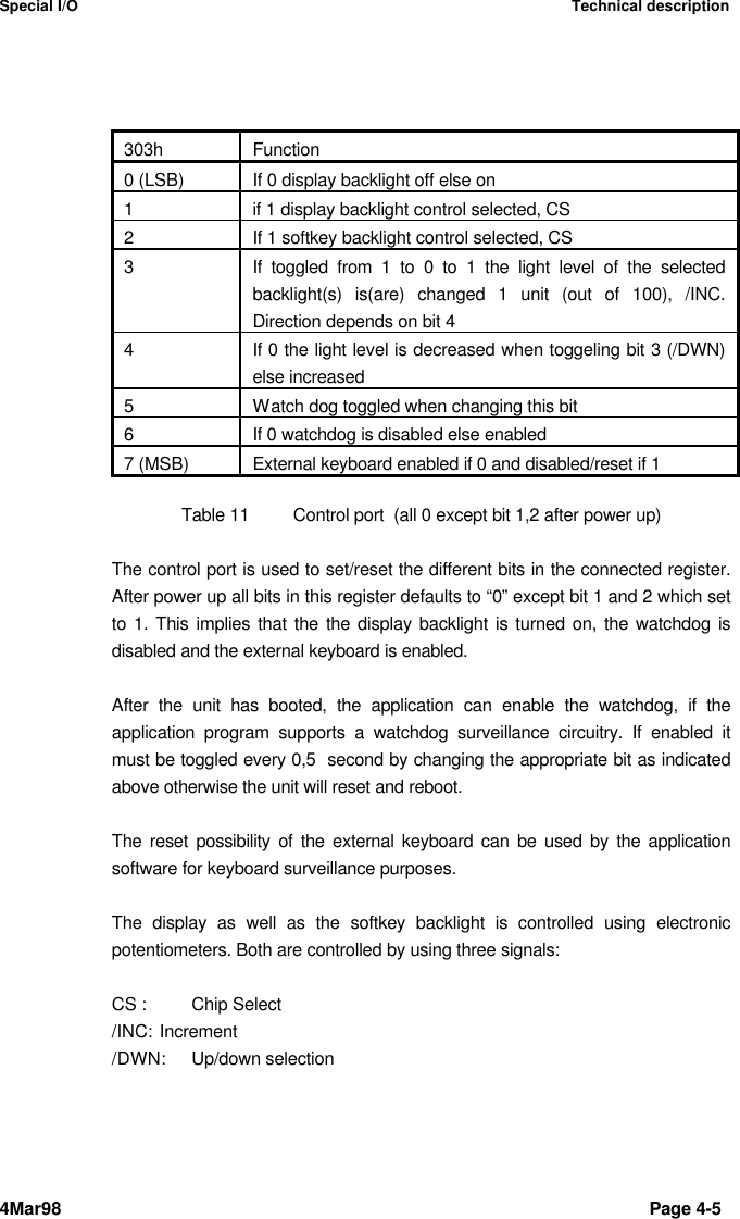
user manual 6

Message TerminalTT-3606EInstallation and Service Manual
Thrane & ThraneMessage TerminalTT-3606EInstallation and Service ManualCopyright Thrane & Thrane A/SALL RIGHTS RESERVED
Information in this document is subject to change without notice and does notrepresent a commitment on the part of Thrane & Thrane A/S.© 1998 Thrane & Thrane A/S. All right reserved. Printed in Denmark.Document Number TT98-109638-A.Release Date: 04 March 1998
Safety SummaryThe following general safety precautions must be observed during all phases of operation, service andrepair of this equipment.  Failure to comply with these precautions or with specific warnings elsewherein this manual violates safety standards of design, manufacture and intended use of the equipment.Thrane & Thrane A/S assumes no liability for the customers failure to comply with these requirements.GROUND THE EQUIPMENTTo minimise shock hazard, the equipment chassis and cabinet must be connected to an electricalground and the cable instuctions must be followed.DO NOT OPERATE IN AN EXPLOSIVE ATMOSPHEREDo not operate the equipment in the presence of flammable gases or fumes.  Operation of anyelectrical equipment in such an environment constitutes a definite safety hazard.KEEP AWAY FROM LIVE CIRCUITSOperating personnel must not remove equipment covers. Component replacement and internaladjustment must be made by qualified maintenance personnel.  Do not replace components with thepower cable connected. Under certain conditions, dangerous voltages may exist even with the powercable removed.  To avoid injuries, always disconnect power and discharge circuits before touchingthem.DO NOT SERVICE OR ADJUST ALONEDo not attempt internal service or adjustments unless another person, capable of rendering first aidresuscitation, is present.DO NOT SUBSTITUTE PARTS OR MODIFY EQUIPMENTBecause of the danger of introducing additional hazards, do not substitute parts or perform anyunauthorized modification to the equipment.COMPASS SAFE DISTANCEMinimum safety distance of 50 cm from the TT-3606E Message Terminal
This page is intentionally left blank
Table of Contents4Mar98 Page iTable of Contents1 Installation............................................................................................................ 1-11.1 Quick system connect and checkout.................................................... 1-21.2 Initial inspection...................................................................................... 1-31.3 Storage .................................................................................................. 1-41.4 Repacking for shipment ........................................................................ 1-51.5 Cabling................................................................................................... 1-61.6 Mounting................................................................................................ 1-72 Description........................................................................................................... 2-12.1 Specifications......................................................................................... 2-22.2 Connectors ............................................................................................ 2-32.2.1 Keyboard connector ..................................................................... 2-32.2.2 Power connector .......................................................................... 2-42.2.3 Parallel printer port........................................................................ 2-52.2.4 Serial ports.................................................................................... 2-63 Service................................................................................................................. 3-13.1 Disassembling........................................................................................ 3-13.2 Configuration ......................................................................................... 3-34 Technical description........................................................................................... 4-14.1 Detailed specification............................................................................. 4-14.2 Special I/O ............................................................................................. 4-35 Mechanical outlines............................................................................................. 5-15.1 TT-3606E .............................................................................................. 5-15.2 Flush mount........................................................................................... 5-35.3 Mounting bracket................................................................................... 5-4
Table of ContentsPage ii 4Mar98This page is intentionally left blank
Quick system connect and checkout Installation4Mar98 Page 1-1 11 InstallationInstallationThis chapter provides specific information about installation of the TT-3606EMessage Terminal and information about initial inspection, storage andrepacking for shipment.Figure 1TT-3606E Message Terminal
Installation Quick system connect and checkoutPage 1-2 4Mar981.11.1 Quick system connect and checkoutQuick system connect and checkoutThe following brief outline may be used to get the TT-3606E Message terminalup and running• Unpack system components• Connect the TT-3606E to the keyboard• Connect the TT-3606E to a DC power sourceThe TT-3606E should then start the actual application program. Please refer themanual for the specific application program.
Initial inspection Installation4Mar98 Page 1-31.21.2 Initial inspectionInitial inspectionWARNINGTo avoid hazardous electrical shock, do not perform electrical tests if thereis any sign of shipping damage to any portion of the front or rear panel orthe outer cover.  Read the safety summary at the front of this manual beforeinstalling or operating the 3606E Message Terminal.Inspect the shipping carton immediately upon receipt for evidence ofmishandling during the transit.  If the shipping carton is severely damaged orwater stained, request that the carrier's agent be present when opening thecarton.  Save the carton packing material for future use.Contents of the shipment should be as listed in the enclosed packing list. If thecontents are incomplete, if there is mechanical damage or defect, or if the3606E Message Terminal does not work properly, notify your dealer.After you unpack the 3606E Message Terminal, inspect it thoroughly for hiddendamage and loose components or fittings.²Inspect the cable harness for stress, loose or broken wires, or broken cabletires.²Examine all the components for loose or missing hardware.  Tighten allloose hardware.
Installation StoragePage 1-4 4Mar981.31.3 StorageStorageThe 3606E may be stored or shipped in temperatures within the limits -40° C to+80° C. It is advisable to protect 3606E from extreme temperature variationwhich can cause excessive condensation. It is recommended that the 3606E isunpacked immediately on delivery.
Repacking for shipment Installation4Mar98 Page 1-51.41.4 Repacking for shipmentRepacking for shipmentThe shipping carton for the 3606E has been carefully designed to protect theMessage Terminal and its accessories during shipment. This carton and itsassociated packing material should be used when repacking for shipment.Attach a tag indicating the type of service required, return address, modelnumber and full serial number. Mark the carton FRAGILE to ensure carefulhandling.If the original shipping carton is not available, the following general instructionsshould be used for repacking with commercially available material.1. Wrap the 3606E in heavy paper or plastic. Attach a tag indicating the type ofservice required, return address, model number and full serial number.2. Use a strong shipping container, e.g. a double walled carton of 160 kg testmaterial.3. Protect the front- and rear panel with cardboard and insert a 7 cm to 10 cmlayer of shock absorbing material between all surfaces of the equipment andthe sides of the container.4. Seal the shipping container securely.5. Mark the shipping container FRAGILE to ensure careful handling.
Installation CablingPage 1-6 4Mar981.51.5 CablingCablingFor any installation it is required that all attached cables are shielded andequipped with shielded connectors, which are properly connected to the shieldof the cable. Furthermore every  shield should have a low impedance connectionto an electrical ground.Before using the TT-3606E Message Terminal for the first time check out thatall cables are correctly wired and fastened.Please notice that the DC-input range applies to the DC voltage measured at thepin's on the power connector on the 3606E. This means that the power cablecharacteristic should be taken into account. The cable should allow the DC,measured at the input pin's on the 3606E power connector, to stay within limitseven though it has to carry a current of 3 A.Please notice, that the wires must be properly connected in the connector andall pin’s for each power input must be connected to the respective wire.A cable using 2 mm2 (AWG 14) wire's of length 4 m fulfils the requirements.Please notice, that the cable connections must be properly installed.
Mounting Installation4Mar98 Page 1-71.61.6 MountingMountingThe TT-3606E Message Terminal may be mounted in several ways.If the mounting bracket is not used, the TT-3606E Message Terminal may beflush mounted in a consol by using the 4 screw holes on the rear.The mounting bracket may be used either to mount the TT-3606E MessageTerminal on a horizontal surface or a vertical surface. In both cases the anglecan be adjusted in steps of 7.5°. This is done by loosening the hand wheelsslightly and then move the upper part of the TT-3606E Message Terminal intothe wanted angle. Please remember to tighten the handwheels again.When assembling the mounting bracket together with the TT-3606E MessageTerminal it is important that the small indications on the cylinders are in-line withthe indications on the rear of TT-3606E Message Terminal.When installing the TT-3606E on a vertical surface it is necessary to mount themounting bracket opposite the way it is mounted for horizontal installation.Please refer to the chapter describing the detailed mechanical outlines of theTT-3606E Message Terminal and mounting bracket.
Installation MountingPage 1-8 4Mar98This page is intentionally left blank
Mounting Description4Mar98 Page 2-1 22 DescriptionDescriptionThis chapter describes the TT-3606E Message Terminal. This encompassesspecifications as well as provides specific information about the availablefeatures and interfaces.
Description SpecificationsPage 2-2 4Mar982.12.1 SpecificationsSpecificationsProcessor 386SX-40MHzRAM 2 MBFlash DISK 2 MBDisplay 10.4” Color TFT flatpanel, 640x480Floppy drive 3.5”Keyboard i/f 5-pin mini-DINParallel printer port 25 pin SubD female connectorSerial port COM1 9 pin SubD male  connector, DTE typeSerial port COM2 9 pin SubD male connector, DTE typeEnvironmental Meets or exceeds all INMARSAT specifications forthe Inmarsat-C Network for SOLAS with distress callfunctions. (CN114 and IEC 945 requirements). MeetsCE-marking (1997) requirements.Power Source 10 to 32 V floating DC, 15 pin SubD femalePower Consumption App. 20 Watts, maximumApp. 13 Watts, typicalFuse Internal automatic recovering poly fuseAmbient Temperature -20°C to 55°C operating-40°C to 80°C storage.Compass safe distance 50 cm(measured in accordance with the standardsspecified in ISO/R 694, Method B)Dimensions H x W x D 221x 297 x 114.5 mm w/o bracket256 x 297 x 114.5 mm w  bracket at vertical positionWeight 3.1 kg (including mounting bracket)Table 1TT-3606E Message Terminal
Connectors Description4Mar98 Page 2-32.22.2 ConnectorsConnectorsThis section describes the functions and pin assignments of connectors foundon the rear of the TT-3606E. Figure 2 shows the connector part of the TT-3606E Message Terminal.Figure 2Rear connectors2.2.1 Keyboard connectorThe figure below indicates the pin assignment of the keyboard connector asseen from the rear of the TT-3606E Message Terminal.N/C † … Clockn+5V „ ƒ GroundN/C ‚ • DataFigure 3Keyboard connector
Description ConnectorsPage 2-4 4Mar982.2.2 Power connectorThe power input connector is a standard 15 pin SubD male connector, locatedon the rear panel of the TT-3606E and the pin assignments are as indicatedbelow. The Remote ON/OFF input makes it possible to place an eventual on/offswitch at any location.Pin Name Signal Description1,2,9,10 + supply 10-32 VDC (Battery Positive input)4,5,12,13 - supply DC Return (Battery Negative input)6Remote ON/OFF ON if connected to “- supply”OFF if floating7,8 SGND Chassis (Secondary GND)Ground GND Shield3,11,14,15 NCTable 2Power connector
Connectors Description4Mar98 Page 2-52.2.3 Parallel printer portThe parallel printer port is a standard 25 pin SubD female connector, located onthe rear panel of the TT-3606E and the pin assignments are as indicated below.Pin Name Signal Description1STRB Strobe2DAT0 Data Bit 03DAT1 Data Bit 14DAT2 Data Bit 25DAT3 Data Bit 36DAT4 Data Bit 47DAT5 Data Bit 58DAT6 Data Bit 69DAT7 Data Bit 710 ACKN Acknowledge11 BUSY Printer Busy12 PE Paper End (out of paper)13 SEL Printer Selected14 ALFD Auto Line Feed15 ERR Printer Error16 INIT Initialise Printer17 SLCT Select Printer18 GND Ground19 GND Ground20 GND Ground21 GND Ground22 GND Ground23 GND Ground24 GND Ground25 GND GroundTable 3Parallel port
Description ConnectorsPage 2-6 4Mar982.2.4 Serial portsThe serial ports are standard 9 pin SubD male connectors, located on the rearpanel of the TT-3606E and the pin assignments are as indicated below.Pin Name Direction Signal Description1DCD input Data Carrier Detect2RxD input Received Data3TxD output Transmitted Data4DTR output Data Terminal Ready5GND Ground6DSR input Data Set Ready7RTS output Request To Send8CTS input Clear To Send9RI input Ring IndicatorTable 4Serial portsThe serial ports comply with the EIA/TIA-232 standard.For full operating specifications for the serial interface, you are kindly requestedto refer to the CCITT Rec. V24 and the EIA/TIA-232 specifications.To interface the TT-3606E to any DCE type of device such as for example theTT-3020C/22C/D Transceiver use a 1:1 RS-232 cable.At a baud rate of 4800 this cable should not exceed 100 meters.
Disassembling Service4Mar98 Page 3-1 33 ServiceServiceThis chapter describes how to disassemble and to service to a level of changingboards/parts.3.13.1 DisassemblingDisassemblingIf you have to disassemble the TT-3606E Message Terminal it is important, thatyou follow the procedure described in this section. Otherwise you will find it verydifficult and you risk to permanently damage the Message Terminal.WARNINGDo not try to disassemble the TT-3606E Message Terminal yourself.This operation must only beperformed by qualified servicepersonnel.The unit is assembled out of three parts:1. Rear plate holding the floppy drive2. Intermediate plate holding the different PCB’s on the rear side and the flatpanel on the front side.3. Plastic front holding the softkey construction and the display window.To get access to the main PCB, backlight PCB (piggy bag on the main PCB)and computer board the following steps should be followed:
Service DisassemblingPage 3-2 4Mar98WARNINGTo avoid hazardous electrical shock,do not touch the two high voltageoutputs of the backlight inverter.1. Make sure the mounting bracket is removed2. Unscrew the 12 counter sunk screws on the rear and the 8 Sub-D stays.3. Gently divide the front part and rear part from each other so that the flexcable connecting the floppy with the main PCB on the intermediate plate canbe removed by releasing the zero-insertion force cable connector mountedon the main PCB (J15).If it is necessary to remove/replace the main PCB it is necessary to remove thebacklight inverter first in order to get access to  two of the screws holding themain PCB.To further get access to the display or soft key PCB’s placed just behind thesoftkeys the following steps further have to be followed1. Dismantle the cables attached to J2 and J3 (just left and right of J15).These cables establish the connections from the main PCB on theintermediate plate and to the softkey PCB’s attached to the plastic front.2. Remove the plastic front from the intermediate plate by unscrewing the 14counter sunk screws.
Configuration Service4Mar98 Page 3-33.23.2 ConfigurationConfigurationThe main PCB, which is shown in figure 4, contains the following jumpers,measurement points and adjustment possibilities:Reference Factory setting orvalue/rangeFunctionW1 Open If closed the computer is resetW2 Closed Connecting/disconnecting powersupply from rest of circuitryW3 120 kHz, ± 2 kHz Switch frequency of switch modepower supplyTP1 0 - 3.6 V DC Output of light sensorTP2 0 - 3 V DC Output to softkey back lightR38 120 kHz, ± 2 kHz Adjustment of switch frequencyTable 5ConfigurationThe jumper W2 can be used to remove the connection between the switchmode power supply and the rest of the circuitry including computer as well asbacklight inverter. The pin assignments for W2 are as follows. Please noticethat ground connection can only be disconnected when the PCB is NOTmounted on the intermediate plate.W2 pin no Function1 2 + 12 V DC, ± 20 %3 4
Service ConfigurationPage 3-4 4Mar985 6 Ground7 89 1011 1213 14 + 5 V DC, ± 10 %15 1617 18 No Connection19 20Table 6Jumper W2The CMOS-setup in the computer may be reset to default by moving the jumpermarked “CLEAR CMOS” on the computer board from position 1-2 to position 2-3 and then back to position 1-2.
Configuration Service4Mar98 Page 3-5Figure 4Main PCB
Service ConfigurationPage 3-6 4Mar98This page is intentionally left blank
Detailed specification Technical description4Mar98 Page 4-1 44 Technical descriptionTechnical descriptionThis chapter gives a detailed description of the TT-3606E Message Terminal.4.14.1 Detailed specificationDetailed specificationThe hardware platform of TT-3606E Message Terminal is PC - compatible. Thetable below gives a more detailed specification of the computer part. Whether ornot these hardware features are used dependents on the installed applicationprogram.Processor 386SX-40MHzData bus 16-bitProcessing ability 32-bitShadow RAM Support for system and video BIOS up to 256 kBin 32 kB blocksDisplay memory 512 kB DRAMIDE HDD interface Supports up to two IDE (AT bus) HDD’sFDD interface Supports up to two FDDsParallel port Bi-directional  (SPP/ECP/EPP modes)Serial ports Two RS-232 (both use 16C550 UART with 16-byte FIFO). Up to 115.200 baud.Real time  clock ALI M6117B internal RTC, battery for up to 10years data retentionDMA channels 7Interrupt levels 15Keyboard interface PS/2Bus speed 8 MHzFlash DISK DiskOnChip2000 from M-Systems.Address: DC000-DDFFFTable 7Detailed specification
Technical description Detailed specificationPage 4-2 4Mar98Figure 5 shows the physical outline of the computer board:Figure 5Computer board
Special I/O Technical description4Mar98 Page 4-34.24.2 Special I/OSpecial I/OSpecial I/O ports have been implemented in the TT-3606E Message Terminal inorder to be able to support some extra features compared to a standard PC.These are• 12 softkeys• Disk change signal from floppy• Backlight control of TFT flat-panel as well as softkeys• Watchdog• Light sensor• Reset of external keyboardThe table below indicates the diffent I/O portsAddress Direction Function300h input status of softkey right anddisk change signal301h input status of softkey left302h output light sensor sample and hold302h input light sensor output303h output control ofdisplay backlight levelsoftkey backlight levelwatch dogkeyboard resetTable 8Special I/O portsThe light level surrounding the equipment is determined by the light sensorcircuitry. A sample/hold of the light level is done by writing to this port two times.The sampled value can then be determined by reading this port afterwards.An 8-bit A/D-converter is used with a reference level of 5V (corresponds to A/Dvalue FFh). The linear light sensor gives an output in the range from 0V to3,60V, thus the light level is in the range from 00h to approximately C0h(255*5V/3,75V).
Technical description Special I/OPage 4-4 4Mar98The tables below indicate the precise function of each bit in the remaining ports.300h Indicates0 (LSB) 0 if right softkey 1 is pressed else 1 (upper)10 if right softkey 2 is pressed else 120 if right softkey 3 is pressed else 130 if right softkey 4 is pressed else 140 if right softkey 5 is pressed else 150 if right softkey 6 is pressed else 1 (lower)6Always “1”7 (MSB) Always “1”Table 9Softkey right301h Indicates0 (LSB) 0 if left softkey 1 is pressed else 1 (upper)10 if left softkey 2 is pressed else 120 if left softkey 3 is pressed else 130 if left softkey 4 is pressed else 140 if left softkey 5 is pressed else 150 if left softkey 6 is pressed else 1 (lower)6Status of disk change signal from floppy7 (MSB) Always “1”Table 10 Softkey leftThe hardware does not provide any deglicth secuitry for the softkeys. This is tobe implemented in software. The keys are physically placed outside line3,7,11,15,19 and 23, if there is a total of 25 lines on the display.The “disk change signal “ is a hardware signal from the floppy drive whichduring access to the floppy indicates (goes to 0) whether or not the floppy hasbeen changed. Can be used in the application software to only read the FAT-table, when the floppy has actual changed.
Special I/O Technical description4Mar98 Page 4-5303h Function0 (LSB) If 0 display backlight off else on1if 1 display backlight control selected, CS2If 1 softkey backlight control selected, CS3If toggled from 1 to 0 to 1 the light level of the selectedbacklight(s) is(are) changed 1 unit (out of 100), /INC.Direction depends on bit 44If 0 the light level is decreased when toggeling bit 3 (/DWN)else increased5Watch dog toggled when changing this bit6If 0 watchdog is disabled else enabled7 (MSB) External keyboard enabled if 0 and disabled/reset if 1Table 11 Control port  (all 0 except bit 1,2 after power up)The control port is used to set/reset the different bits in the connected register.After power up all bits in this register defaults to “0” except bit 1 and 2 which setto 1. This implies that the the display backlight is turned on, the watchdog isdisabled and the external keyboard is enabled.After the unit has booted, the application can enable the watchdog, if theapplication program supports a watchdog surveillance circuitry. If enabled itmust be toggled every 0,5  second by changing the appropriate bit as indicatedabove otherwise the unit will reset and reboot.The reset possibility of the external keyboard can be used by the applicationsoftware for keyboard surveillance purposes.The display as well as the softkey backlight is controlled using electronicpotentiometers. Both are controlled by using three signals:CS : Chip Select/INC: Increment/DWN: Up/down selection
Technical description Special I/OPage 4-6 4Mar98If CS is “1” the electronic potentiometer is selected and the /INC and /DWNsignals can be used to adjust the electronic potentiometer and thus the lightlevel. If CS is “0” these two signals will not imply any change. Every time the/INC-bit is toggled the potentiometer is adjusted 1/100 of its maximum value.The direction is controlled by the /DWN-bit. If it is 0 the light level is decreasedwhere as a 1 will imply an increase when the /INC bit is toggled.In this way the application can control the potentiometers to obtain any of its 100different positions/levels.The /INC bit may not be changed more often than every 4 µsec.Both potentiometers can be adjusted simultaneously in the same direction bysetting both CS bits to “1”.To make sure that the position of the potentiometers are known by theapplication software after power up both potentiometers should be initialised with100 pulses in either up or down. It is recommended to decrease both backlightsto the minimum level at power up.The relation between light level and potentiometer position is not identical for thedisplay backlight and the softkey backlight. For the softkey back light there is a1:1 relation. With respect to the display backlight there is a 1:1 relation frompotentiometer position 100 (maximum light) down to approximately 60. Below 60the display backlight level will not change.In order to completely turn off the backlight it is necessary to use the displaybacklight on/off bit and set it to 1.A way to cope with the display backlight characteristic is to have two displaysetups/styles: one used during daylight (bright colors, but not red) and one usedduring night (red characters and graphics on a black background).
Special I/O Technical description4Mar98 Page 4-7
Technical description Special I/OPage 4-8 4Mar98This page is intentionally left blank
Index4Mar98 Page 5-1 55 Mechanical outlinesMechanical outlinesThis chapter shows the dimensions of the TT-3606E Message Terminal as wellas the mounting stencils for the different ways of mounting the TT-3606EMessage Terminal.5.15.1 TT-3606ETT-3606EFigure 6 and 7 shows the dimensions of the TT-3606E Message Terminal.Figure 6TT-3606E Message Terminal
Mechanical outlinesPage 5-2 4Mar98Figure 7TT-3606E Message Terminal
Index4Mar98 Page 5-35.25.2 Flush mountFlush mountFigure 8 indicates the dimension of the panel cut-out and position of mountingholes when mounting the TT-3606E Message Terminal in a consol.Figure 8TT-3606E Message Terminal
Mechanical outlinesPage 5-4 4Mar985.35.3 Mounting bracketMounting bracketFigure 9 indicates the position of the mounting holes for the  mounting bracket.Figure 9TT-3606E Message Terminal

Navigation menu