Trimble 9414-450 GPS data transciever User Manual TRIMMARK III Operation Manual
Trimble Navigation Ltd GPS data transciever TRIMMARK III Operation Manual
UserManual.wiki
>
Trimble
>
9414-450 User Manual
>
Operations Manual
Contents
1.
Operations Manual
2.
User Manual
Operations Manual
Navigation menu
Upload a User Manual
Namespaces
Wiki Guide
HTML
PDF
Info
Views
User Manual
Discussion / Help
Navigation


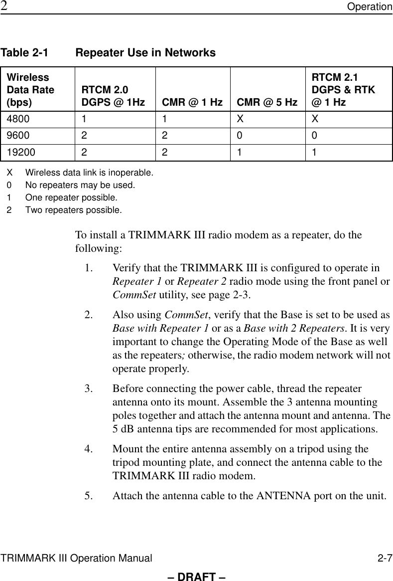
![xviii TRIMMARK III Operation ManualPreface– DRAFT –Document ConventionsItalics identify software menus, menu commands, dialog boxes, and the dialog box fields.SMALL CAPITALS identify DOS commands, directories, filenames, and filename extensions.Courier represents messages printed on the screen. Courier Bold represents information that you must type in a software screen or window.Helvetica Bold identifies a software command button.[Ctrl] is an example of a hardware function key that you must press on a personal computer (PC). If you must press more than one of these at the same time, this is represented by a plus sign, for example, [Ctrl] + [C].](https://usermanual.wiki/Trimble/9414-450.Operations-Manual/User-Guide-80394-Page-18.png)