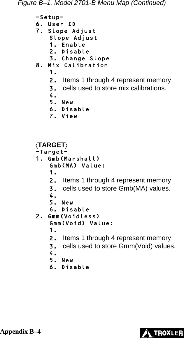
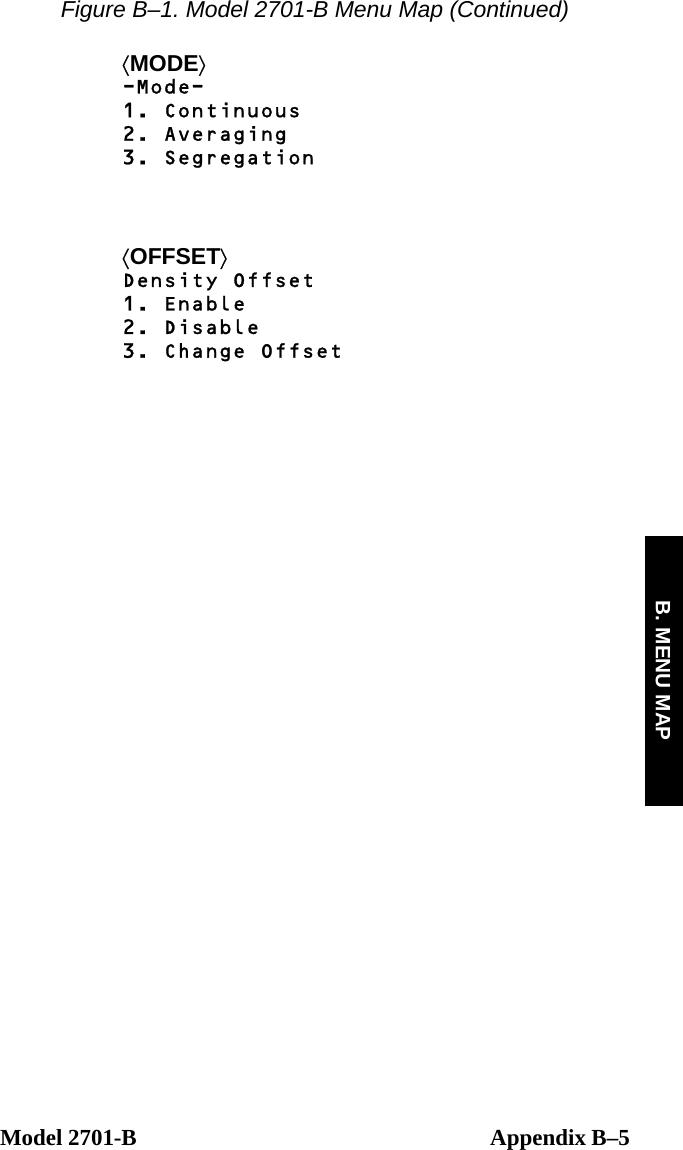
Troxler Electronic Laboratories TROXLER2701-B PaveTracker(tm) Plus User Manual Manual of Operation and Instruction

Troxler Electronic Laboratories, Inc. PaveTracker(tm) Plus Manual of Operation and Instruction

User Manual

Manual of Operation and Instruction        Model 2701-B PaveTracker™ Plus            Troxler Electronic Laboratories, Inc. 3008 Cornwallis Road  •  P.O. Box 12057 Research Triangle Park, NC  27709 Phone:  1.877.TROXLER Outside the U.S.A.:  +1.919.549.8661 Fax:  +1.919.549.0761 www.troxlerlabs.com
    Troxler gauges are protected by U.S. and foreign patents. The Model 2701-B PaveTracker™ Plus is protected by U.S. Patents 6,400,161 and 6,677,763.     Copyright © 2004, 2005  Troxler Electronic Laboratories, Inc. All Rights Reserved  No part of this manual may be reproduced or transmitted in any form or by any means, electronic or mechanical, including photocopying, recording, or information storage and retrieval systems, for any purpose without the express written permission of Troxler Electronic Laboratories, Inc.       Fantastic is a trademark of Dow Consumer Products, Inc. 409 is a trademark of the Clorox Company. Excel, HyperTerminal, Microsoft and Windows are registered trademarks of Microsoft Corporation. PaveTracker is a trademark of Troxler Electronic Laboratories, Inc. WD-40 is a registered trademark of the WD-40 Company.       PN 113045 July 2005 Edition 2.1 ii
Model 2701-B  iii TROXLER SERVICE CENTERS  Troxler Corporate Headquarters 3008 Cornwallis Road P.O. Box 12057 Research Triangle Park, NC  27709 Phone:  1.877.TROXLER (1.877.876.9537) Outside the U.S.A.:  +1.919.549.8661 Fax:  +1.919.549.0761 Web:  www.troxlerlabs.com  Technical Support Phone:  1.877.TROXLER (1.877.876.9537) E-mail:  TroxTechSupport@troxlerlabs.com    Midwestern Branch Office 1430 Brook Drive Downers Grove, IL  60515 Fax:  630.261.9341    Western Regional Branch Office 11300 Sanders Drive, Suite 7 Rancho Cordova, CA  95742 Fax:  916.631.0541    Southwestern Branch Office 2000 East Randol Mill Road Suite 611 Arlington, TX  76011 Fax:  817.275.8562  Florida Service Center 2376 Forsyth Road Orlando, FL  32807 Fax:  407.681.3188   Canadian Branch Office 7125 Pacific Circle, Unit 13 Mississauga, Ontario  L5T-2A5 Canada Fax:  905.564.7092   Troxler European Subsidiary Troxler Electronics GmbH Gilchinger Strasse 33 D.82239 Alling nr. Munich, Germany Phone:  ++49.8141.71063 Fax:  ++49.8141.80731 E-mail:  troxler@t-online.de
iv   HOW TO USE THIS MANUAL  Congratulations on the purchase of the Troxler Model 2701-B PaveTracker™ Plus. Troxler, the leader in density gauge technology, now offers the PaveTracker Plus, an electromagnetic sensing device that quickly gives an indication of the density of asphalt pavement.  The Model 2701-B Manual of Operation and Instruction contains information on safely using this gauge. Also included in this manual are safety warnings, gauge setup, troubleshooting, and general maintenance.
Model 2701-B  v CONVENTIONS USED IN THIS MANUAL  Throughout this manual, symbols and special formatting are used to reveal the purpose of the text as follows:  WARNING Indicates conditions or procedures that, if not followed correctly, may cause personal injury.  CAUTION Indicates conditions or procedures that, if not followed correctly, may cause equipment damage.  NOTE Indicates important information that must be read to ensure proper operation.  ⟨KEY⟩  Angle brackets and a different typestyle indicate a key or character (number or letter) to press on the gauge keypad. For example, “Press ⟨STORE⟩” means to press the key labeled STORE. DISPLAY  A different typestyle is used in text to indicate information or messages displayed on the gauge. DISPLAY - Typestyle and shading used to simulate PaveTracker display ♦  Diamonds indicate a list of things needed (such as equipment) or things to know.   Check marks indicate the performance of an action. With lists of check marks, follow the instructions in the order of the check marks.   Triangles indicate that more than one option is available. Carefully select the option that applies.
FCC REGULATIONS  Troxler’s Model 2701-B PaveTracker™ Plus has been tested and found to comply with the limits for a Class B digital device, pursuant to Part 15 of the Federal Communications Commission (FCC) Rules. These limits are designed to provide reasonable protection against harmful interference in a residential installation. This equipment generates, uses and can radiate radio frequency energy and, if not installed and used in accordance with the instructions, may cause harmful interference to radio communications. However, there is no guarantee that interference will not occur in a particular installation. If this equipment does cause harmful interference to radio or television reception, which can be determined by turning the equipment off and on, the user is encouraged to try to correct the interference by one or more of the following measures:    Reorient or relocate the receiving antenna.   Increase the separation between the equipment and receiver.   Connect the equipment to an outlet on a circuit different from that to which the receiver is connected.   Consult the dealer or an experienced radio/TV technician for help.  Changes or modifications to the PaveTracker Plus that are not expressly approved by Troxler Electronic Laboratories, Inc. could void the user's authority to operate the equipment.  vi
Model 2701-B  vii TABLE OF CONTENTS  CHAPTER 1. INTRODUCTION TO THE MODEL 2701-B Introduction................................................................................... 1–2 Features......................................................................................... 1–4 Gauge Parts and Accessories........................................................ 1–6 Unpacking and Inspection ............................................................ 1–7   CHAPTER 2. GETTING STARTED Keypad.......................................................................................... 2–2 Turning the PaveTracker Plus On................................................. 2–4 Status............................................................................................. 2–6 Setup Menu................................................................................... 2–7 Target.......................................................................................... 2–14 Mode........................................................................................... 2–16   CHAPTER 3. ADJUSTING MEASUREMENTS Introduction................................................................................... 3–2 Offset ............................................................................................ 3–3 Slope Adjust.................................................................................. 3–6 Mix Calibration............................................................................. 3–7   CHAPTER 4. USING THE GAUGE Taking a Reference Reading......................................................... 4–2 Preparing a Test Site..................................................................... 4–4 Taking Measurements................................................................... 4–5 Recall.......................................................................................... 4–11   CHAPTER 5. PROJECT DATA Handling Project Data................................................................... 5–2 Storing Data.................................................................................. 5–7
viii   TABLE OF CONTENTS (Continued)  APPENDIX A. TROUBLESHOOTING AND SERVICE Troubleshooting............................................................................A–2 Batteries........................................................................................A–3 Cleaning the Base and Top Shell..................................................A–5 Replacing the Protective Cover...................................................A– 6 Replacement Parts........................................................................A–7 Returning the Gauge for Service..................................................A–8 Troxler Service Centers................................................................A–9   APPENDIX B. MENU MAP Menu Map Description.................................................................B–2   APPENDIX C. MODEL 2701-B SPECIFICATIONS Measurement Specifications.........................................................C–2 Electrical Specifications...............................................................C–3 Mechanical Specifications............................................................C–4   INDEX   WARRANTY
Model 2701-B  ix LIST OF FIGURES  Figure Title Page  1–1  Model 2701-B PaveTracker Plus .............................. 1–3  2–1  Model 2701-B Keypad.............................................. 2–2  3–1  Determining the Offset Using Gyratory Samples .....3–4  B–1  Model 2701-B Menu Map.........................................B–3     LIST OF TABLES  Table Title Page  2–1  Model 2701-B Keypad Functions............................. 2–3
x   NOTES
 Model 2701-B  1–1 1. INTRODUCTION CHAPTER 1  INTRODUCTION TO THE MODEL 2701-B    This chapter provides a brief overview of the Troxler Model 2701-B PaveTracker™ Plus, and includes a list of the gauge parts and accessories, and instructions for unpacking and inspecting the gauge.   CONTENTS  Introduction................................................................................... 1–2  Features......................................................................................... 1–4  Gauge Parts and Accessories........................................................ 1–6  Unpacking and Inspection ............................................................ 1–7
1–2   INTRODUCTION  Troxler, the leader in density gauge technology, now offers the Model 2701-B PaveTracker Plus (see Figure 1–1), an electromagnetic sensing device that quickly gives an indication of the density of asphalt pavement. The advanced technology in the patented PaveTracker Plus allows rapid and reliable measurements. The PaveTracker Plus can be used on existing asphalt pavements or on freshly placed mats. The unit is ideal for performing quick quality control measurements to check for segregation, areas of low density, and overall pavement uniformity.  The PaveTracker Plus is a precision device that is designed to provide many years of trouble-free service. As any precision device, the PaveTracker Plus requires reasonable care and maintenance to ensure its accuracy and reliability. The user should:  ♦  Keep the unit clean and free of all road debris. ♦  Return the unit to Troxler for yearly re-calibration and inspection. ♦  Ensure that the unit remains sealed at all times. There are no field-serviceable components inside the unit. Opening the case will affect the integrity of the unit and therefore will void the warranty.
 Model 2701-B  1–3 1. INTRODUCTION TELESCOPINGHANDLECARRYINGHANDLEDISPLAYKEYPADPOWERSWITCHSERIALPORTBATTERYCHARGERINPUT  Figure 1–1. Model 2701-B PaveTracker Plus
1–4   FEATURES  The PaveTracker Plus (see Figure 1–1) incorporates a number of features that provide unmatched efficiency, usability, and flexibility.  The PaveTracker Plus takes density measurements using electromagnetic sensing technology, eliminating the need for government licenses or special training. Measurements are completed within 2 seconds, saving time and money.  The unit’s memory can store approximately 1000 readings for later viewing, printing, or downloading.  Both the 30-button keypad and 4 x 20 liquid crystal display (LCD) screen are backlit, making them easy to see, day or night.  The gauge includes a replaceable protective cover on its bottom surface. The protective cover provides thermal protection for the gauge’s internal components and protects the bottom surface of the gauge against wear.   The carrying case for the Model 2701-B includes a built-in reference standard, which provides a density measurement standard for taking reference readings.  The PaveTracker Plus’s advanced software provides three test modes (continuous, averaging, and segregation) for greater flexibility and multiple applications. The software also provides automatic calculations (average density, percent maximum density, percent air voids, and so on) for greater ease of use.  Gauge measurements can be adjusted using a density offset, slope adjust, or mix calibration to increase accuracy on specific materials.  Both an ac charger and a dc adapter are included with the PaveTracker Plus, enabling the unit to be recharged from an ac outlet or a 12 V dc system.
 Model 2701-B  1–5 1. INTRODUCTION The gauge features two audible indicators, an internally mounted beeper, as well as a louder, external one mounted on its underside. The internal beeper emits a short tone in response to a valid keystroke on the keypad. It sounds a longer tone when the operator presses an invalid key or if the gauge displays an error message. The external beeper performs the same functions, and can be enabled or disabled as desired by the operator.  A serial communications port is mounted on the front of the gauge. The serial port is used to output data to a serial device, such as a computer or printer.  The detachable telescoping handle reduces bending for gauge operations. A second carrying handle is provided for ease of transporting the gauge.
1–6   GAUGE PARTS AND ACCESSORIES  1. The gauge is the portable electromagnetic sensing device containing all electronic modules and a rechargeable battery pack.  2. The carrying case for the Model 2701-B includes a built-in reference standard, which provides a density measurement standard for taking reference readings.  3. The ac charger and dc adapter are used to charge the gauge batteries. The ac charger accepts 100 – 240 V ac, 47 – 63 Hz and supplies 12 V dc at 1.8 A. The dc adapter allows recharging from a 12 V dc system, such as a vehicle cigarette lighter.  4. The manual (not shown) details how to operate and maintain the gauge.  5. A printer (optional, not shown) connects to the gauge for printing data.
 Model 2701-B  1–7 1. INTRODUCTION UNPACKING AND INSPECTION  NOTE To ensure the safe return of the PaveTracker Plus to Troxler for repair or maintenance, please keep the original shipping boxes and all packing materials.  Upon receipt of the gauge from the factory:  1.  Perform a complete inspection and inventory. If the shipping case and/or any other part or accessory appears damaged, notify the carrier and your Troxler representative immediately.  2.  Check the shipping case for the following:  ♦  Model 2701-B PaveTracker Plus ♦  Carrying Case (PN 113034) ♦  Telescoping handle (PN 113017) ♦  AC charger (PN 110403) ♦  DC adapter (PN 104156) ♦  Manual of Operation and Instruction (PN 113045)  3.  Lift the gauge from the carrying case and inspect the outside surface for damage.
1–8   NOTES
 Model 2701-B  2–1 2. GETTING STARTED CHAPTER 2  GETTING STARTED    This chapter provides details on getting started with the Model 2701-B PaveTracker Plus. It describes the gauge keypad, and provides instructions for turning the gauge on, and setting up the gauge.   CONTENTS  Keypad.......................................................................................... 2–2  Turning the PaveTracker Plus On................................................. 2–4  Status............................................................................................. 2–6  Setup Menu................................................................................... 2–7 Set Units................................................................................. 2–8 Date/Time............................................................................... 2–8 Temperature (Optional)........................................................ 2–10 Customer Name.................................................................... 2–11 External Beeper.................................................................... 2–12 User ID................................................................................. 2–12 Slope Adjust......................................................................... 2–13 Mix Calibration.................................................................... 2–13  Target.......................................................................................... 2–14 Enable a Target Value.......................................................... 2–14 Enter a New Target Value.................................................... 2–15 Disable the Target Value...................................................... 2–15  Mode........................................................................................... 2–16
2–2   KEYPAD  The Model 2701-B keypad (Figure 2–1) allows the operator to access the gauge software. Troxler designed the keypad for ease of use, with large keys and an anti-glare coating. Note that the function keys are available only when the Ready screen is displayed. Table 2–1 describes the function of each key.      0147258369ENTERALPHALOCKREFMODETARGETOFFSETESCRECALLSTOREPROJSTATUS YES NOLIGHTBACKSPACESPACE START+-SETUPRTM-Ready- Offset:Y04/08/2004 04:08 PMPrj: MY PROJECTMode: Continuous  Figure 2–1. Model 2701-B Keypad
 Model 2701-B  2–3 2. GETTING STARTED Table 2–1. Model 2701-B Keypad Functions  KEY  FUNCTION  PAGE ⟨STORE⟩ Store the most recent data in the current project file.  5–7 ⟨STATUS⟩ Displays gauge status information.  2–6 ⟨RECALL⟩ Display the most recent data.  4–11 ⟨PROJ⟩ Select or create a project file and view, output, or erase project data file.  5–2 ⟨SETUP⟩ Displays the gauge Setup menu.  2–7 ⟨TARGET⟩ Select, enter, or disable a Gmb (Marshall) or Gmm (Voidless density) value.  2–14 ⟨MODE⟩ Select the measurement mode, Averaging, Continuous, or Segregation.  2–16 ⟨OFFSET⟩ Enable, disable, or change a density offset.  3–3 ⟨REF⟩ Take a reference reading.  4–2 ⟨SPACE⟩ Enter a space.   ⟨LIGHT⟩ Manually toggle the keypad and LCD backlights on and off.  2–5 ⟨YES⟩ Respond yes to yes/no questions.   ⟨NO⟩ Respond no to yes/no questions.   ⟨ESC⟩ Return the display to the Ready screen without storing or updating the data.   ⟨0⟩ .. ⟨9⟩ Enter numbers and access menu options.   ⟨.⟩ Enter a decimal point.   ⟨ALPHA LOCK⟩ Access the letters.   ⟨BACK SPACE⟩ Moves cursor back one space.   ⟨↑⟩, ⟨↓⟩ Scroll through menu options or view screens.   ⟨ENTER/START⟩ Accept data entry or begin a measurement.   ⟨A⟩ .. ⟨Z⟩ Enter letters. Access these keys by first pressing ⟨ALPHA LOCK⟩.
2–4   TURNING THE PAVETRACKER PLUS ON  To turn on the PaveTracker Plus, press the power switch located on the front panel next to the serial port (see Figure 1–1).  NOTE To turn off the PaveTracker Plus, press and hold the power switch for two seconds.  The gauge displays the model number, battery voltage, software version, and unit serial number as shown below:     -Model 2701B- Battery Volts: X.X   V#.## SN: ###    Press <ENTER>  Press the ⟨ENTER/START⟩ key to continue. The software performs two tests to ensure that the gauge is working properly. The gauge first performs a brief self-test, followed by a test of the display.  Following the test period, the gauge displays the Ready screen:  -Ready- Offset:Y mm/dd/yyyy hh:mm AM Prj: PROJECT NAME Mode: Continuous  The operator can access any gauge function from the Ready screen. On the first line, the Ready screen displays whether a density offset (see page 3–3) is enabled. When a slope adjust (see page 2–13) is enabled, the symbol / is displayed on the top line of the Ready screen.  The second line shows the current date and time. The third line shows the current project (see page 5–2), if any. The last line shows the measurement mode (see page 2–16).
 Model 2701-B  2–5 2. GETTING STARTED The PaveTracker Plus features a backlit keypad and display. To toggle the backlights on and off, press the ⟨LIGHT⟩ key.  NOTE The keypad and display backlights increase the power consumption of the unit. To conserve battery life, Troxler recommends that the backlights be used only when necessary.  To conserve power, the PaveTracker Plus provides a sleep mode, as well as an automatic shutdown. If no key is pressed for five minutes, the gauge enters sleep mode. In sleep mode, the display and keypad backlights, and most of the electronics are turned off, but all data and gauge settings are protected. To exit sleep mode, press any key. If no key is pressed for 60 minutes, the gauge shuts down automatically.  NOTE If the gauge goes into sleep mode while in the continuous measurement mode (see page 2–16), the display returns to the Ready screen. In averaging or segregation mode, the gauge maintains its current state when it enters sleep mode.  The gauge software monitors the battery voltage. If the voltage falls below 6.0 V dc, the gauge displays a low battery symbol () in the upper right of the Ready screen. Recharge the batteries as described on page A–3. After charging, the battery voltage should be between 6.8 and 7.2 V dc. If the voltage falls below 5.5 V dc, the gauge powers down automatically after completing any memory store functions already in progress.
2–6   STATUS  The gauge Status display enables the operator to view gauge status information, including the battery voltage, internal temperature, selected measurement units (see page 2–8), and the time and date of the last reference reading (see page 4–2). To access this information, press the ⟨STATUS⟩ key. The gauge displays:       -Status-       Batt. Volts: #.# Internal Temp: ##°F Units: English  Last Ref:           hh:mma mm/dd/yy    To scroll through the displays, use the up and down arrow keys. Return to the Ready screen by pressing the ⟨ESC⟩ key.
 Model 2701-B  2–7 2. GETTING STARTED SETUP MENU  After turning the gauge on for the first time, set up the software. The gauge stores the software setup, so the operator does not need to enter a new setup each time the gauge is turned on.  The gauge setup includes the measurement units (Metric or English), date and time, temperature, customer name, external beeper setup, user ID, slope adjust, and mix calibration.  To access the Setup menu, press the ⟨SETUP⟩ key. The gauge displays:        -Setup-       1. Set Units 2. Date/Time 3. Temperature        -Setup-       4. Customer Name 5. External Beeper 6. User ID        -Setup-       7. Slope Adjust 8. Mix Calibration   To scroll through the Setup menu, use the arrow keys (screens that have options the operator can scroll through are indicated with the up/down arrow symbol in the upper right corner of the screen). To select a menu option, use the numeric key that corresponds to the option. To return to the Ready screen, press the ⟨ESC⟩ key.  The remainder of this section provides details on the setup options.
2–8   SET UNITS  The gauge can display measurement results in either metric (SI) or English units. To set the units, press ⟨1⟩ at the Setup menu shown on page 2–7. The gauge displays:        -Units- 1. English 2. Metric  Press # to Select  Select the desired measurement units by pressing the corresponding numeric key. The gauge displays the new units, then returns to the Setup menu.   DATE/TIME  The Date/Time function allows the operator to change the date and time, and to select the display format for each. To access the Date/Time menu, press ⟨2⟩ at the Setup menu shown on page 2–7. The gauge displays the Date/Time menu:      -Date/Time-     1. Change Time 2. Change Date 3. Time Format      -Date/Time-     4. Date Format    From this screen, the operator may change the time, date, or time/date display format. Use the up and down arrows to scroll between the menu options. To select a menu option, press the corresponding numeric key. To return to the Setup menu, press the ⟨ESC⟩ key.
 Model 2701-B  2–9 2. GETTING STARTED Change Time  To change the time, press ⟨1⟩ at the Date/Time menu. The gauge displays:        hh:mm AM  Arrows toggle AM/PM    Input Time and    Press <ENTER>  (Note that in this example, the time is displayed in AM/PM format. To change the format, see the Time Format section on page 2–10.) To accept the displayed time, press ⟨ENTER/START⟩. To change the time, use the numeric keys to enter the new time, and the arrow keys to toggle between AM and PM. Press ⟨ENTER/START⟩. The gauge sets the time and returns to the Date/Time menu.   Change Date  To change the date, press ⟨2⟩ at the Date/Time menu. The gauge displays:       04/08/2004      mm/dd/yyyy    Input Date and    Press <ENTER>  (Note that in this example, the time is displayed in mm/dd/yyyy format. To change the date format, refer to the Date Format section on page 2–10.) To accept the displayed date, press ⟨ENTER/START⟩. To change the date, use the numeric keys to enter the new date. When finished, press ⟨ENTER/START⟩. The gauge sets the date and returns to the Date/Time menu.
2–10   Time Format  The gauge can display the time in either AM/PM or 24-hour format. To select the desired time format, press ⟨3⟩ at the Date/Time menu. The gauge displays:     -Time Format- 1. AM/PM 2. 24-Hour   Use the numeric keys to select the desired time format. The gauge sets the time format and returns to the Date/Time menu.   Date Format  The gauge can display the date in either mm/dd/yyyy or dd/mm/yyyy format, where mm = month, dd = day, and yyyy = year. To select the desired date format, press ⟨4⟩ at the Date/Time menu. The gauge displays:      -Date Format- 1. mm/dd/yyyy 2. dd/mm/yyyy   Use the numeric keys to select the desired format. The gauge sets the date format and returns to the Date/Time menu.   TEMPERATURE (OPTIONAL)  An infrared sensor that measures the temperature of the mat is available as an option for the gauge. If this option is installed, press ⟨3⟩ at the Setup menu shown on page 2–7 to display the temperature reading. Press the ⟨ESC⟩ key to return to the Setup menu.
 Model 2701-B  2–11 2. GETTING STARTED CUSTOMER NAME  The Model 2701-B can store a customer name of up to 12 characters. To enter a customer name, press ⟨4⟩ at the Setup menu shown on page 2–7. The gauge displays the current customer name on the second line.    Customer Name is:       CUSTOMER     Change Name?    <YES> or <NO>  To change the customer name, press ⟨YES⟩. The gauge displays:     Customer Name: A     Input Name and    Press <ENTER>  Press the ⟨ALPHA LOCK⟩ key to enable the alphabetic keys on the gauge. When the alphabetic keys are enabled, the symbol A appears in the upper right of the display, as shown above.  Enter the new name and press the ⟨ENTER/START⟩ key. The gauge stores the new customer name, then returns to the Setup menu.
2–12   EXTERNAL BEEPER  The PaveTracker Plus is equipped with an external beeper mounted on its underside. The external beeper can be enabled or disabled as desired. To control the external beeper, press ⟨5⟩ on the Setup menu shown on page 2–7. The gauge displays:   -External Beeper- 1. ON 2. OFF   Press # to Select  Press ⟨1⟩ to enable the external beeper or ⟨2⟩ to disable it. The gauge sets the external beeper function to the desired state, displays a brief confirmation message, and returns to the Setup menu.   USER ID  The PaveTracker Plus stores a three-character user ID with each measurement. To enter or change the user ID, press ⟨6⟩ on the Setup menu shown on page 2–7. The gauge displays:       User ID          XXX    Do You Want To   Change User ID? To change the user ID, press ⟨YES⟩. The gauge displays:    Input User ID  A  <ALPHA> for Letters    Press <ENTER>  Press the ⟨ALPHA LOCK⟩ key to enable the alphabetic keys on the gauge. When the alphabetic keys are enabled, the symbol A appears in the upper right of the display, as shown above.  Enter the new user ID and press ⟨ENTER/START⟩. The gauge stores the new user ID and returns to the Setup menu.
 Model 2701-B  2–13 2. GETTING STARTED SLOPE ADJUST  The Slope Adjust function is used to adjust gauge measurements, as described on page 3–6.   MIX CALIBRATION  The Mix Calibration function is used to adjust gauge measurements, as described on page 3–7.
2–14   TARGET  The Model 2701-B can store up to four Gmb (Marshall) and four Gmm (Voidless density) target values. A Gmb value is the bulk density of a material, often determined using the Marshall method. A Gmm value is the maximum theoretical density for a test material as obtained in laboratory tests. The gauge uses target values to determine the percent compaction and/or percent voids (if a Gmm value is entered) as compared to the measured density of the test material.  With the Target function, the operator can enter a new target value, enable a stored target value, or disable a target value. To access the Target function, press the ⟨TARGET⟩ key. The gauge displays the Target menu:       -Target- 1. Gmb(Marshall) 2. Gmm(Voidless)  Press # to Select  To enter, enable, or disable a Gmb (Marshall) or Gmm (Voidless density) value, press the corresponding numeric key. For example, to edit the Gmb (Marshall) value, press ⟨1⟩. The gauge displays the Gmb(MA) Value: menu shown below. The Gmm(Void) Value: menu is similar and operates in the same manner. Gmb(MA) Value: 1. #.#    2. #.# 3. #.#    4. #.# 5. New    6. Disable  The target value menu shows the four stored target values (if any) and the New and Disable options.   ENABLE A TARGET VALUE  To enable a displayed target value, press the corresponding numeric key on the target value menu. The gauge enables the target value and returns to the Ready screen.
 Model 2701-B  2–15 2. GETTING STARTED ENTER A NEW TARGET VALUE  To enter a new target value, press ⟨5⟩ at the target value menu. The gauge displays: Gmb(Marshall) Value:       0.0   pcf     Press <ENTER>  Use the numeric and decimal keys to enter the target value. Press the ⟨ENTER/START⟩ key. The gauge displays: Gmb(MA) = ##.#    Do You Want to   Save This Value    for Late Use?  To store the value, press the ⟨YES⟩ key. To use the value now without storing it for later use, press the ⟨NO⟩ key.  If the operator presses the ⟨YES⟩ key to store the target value, the gauge displays: Select Memory Cell 1. #.#    2. #.# 3. #.#    4. #.# Press # To Select  The gauge can store the target value in one of four memory cells. Use the numeric keys to store the target value. Note that this will replace any target value that was previously stored in the memory cell. The gauge enables the target value, displays a brief confirmation message and returns to the Ready screen.   DISABLE THE TARGET VALUE  To disable the current target value, press ⟨6⟩ at the target value menu. The gauge disables the target value, displays a brief confirmation message, and returns to the Ready screen.
2–16   MODE  The Model 2701-B provides three measurement modes:  ♦  In continuous mode, the gauge takes a measurement and updates the display every second. This mode is used for typical quality control measurements.  ♦  In averaging mode, the operator can take up to 30 measurements at selected locations. The gauge then calculates the average of the measurements. This mode enables the operator to determine the average density over a selected area. The Store function (see page 5–9) records the most recent results screen when in this mode.  ♦  In segregation mode, the operator can take up to 30 measurements at selected locations. The gauge then displays the high, low, and average density of the readings. This mode enables the operator to determine the degree of segregation in the area being measured. The Store function (see page 5–9) records the most recent results screen when in this mode.  Before taking a measurement, select the appropriate measurement mode. To select a measurement mode, press the ⟨MODE⟩ key. The gauge displays:         -MODE- 1. Continuous 2. Averaging 3. Segregation  Press the numeric key that corresponds to the desired measurement mode. The gauge enables the selected mode, displays a brief confirmation message, and returns to the Ready display.
 Model 2701-B  3–1 3. ADJUSTING MEASUREMENTSCHAPTER 3  ADJUSTING MEASUREMENTS    This chapter explains how to adjust gauge measurements using density offsets and slope adjust values, as well as how to create a special mix calibration for a particular material.   CONTENTS  Introduction................................................................................... 3–2  Offset ............................................................................................ 3–3 Determining the Density Offset ............................................. 3–3 Managing Density Offsets...................................................... 3–5  Slope Adjust.................................................................................. 3–6  Mix Calibration............................................................................. 3–7 Enable a Mix Calibration ....................................................... 3–7 Determining a New Mix Calibration...................................... 3–8 Disable the Mix Calibration................................................. 3–10
3–2   INTRODUCTION  As described on page 4–2, Troxler recommends taking a reference reading each day that the gauge will be used, and periodically while taking measurements. The reference reading consists of placing the gauge on the reference standard contained in the gauge carrying case and pressing the ⟨Ref⟩ key. The density read by the gauge is then compared to the known density of the reference standard. The result of this comparison is used to automatically adjust gauge measurements.  For increased accuracy, measurements can be adjusted using density offset and slope adjust values described in the following sections.   To determine the density offset, take a gauge reading and compare the measured value to the actual density, as measured by an alternate method (such as using a nuclear gauge or extraction and analysis of a road core). A density offset can also be determined using a gyratory-compacted specimen.  For a given material, the density offset and slope adjust values can also be determined using the Mix Calibration function described on page 3–7. The Slope Adjust function enables the operator to enter the slope value manually.
 Model 2701-B  3–3 3. ADJUSTING MEASUREMENTSOFFSET  To improve the accuracy of the PaveTracker for a specific material of known density, the unit can be calibrated using a density offset. A density offset can be determined from in-place measurements or from 150-mm gyratory-compacted samples.   DETERMINING THE DENSITY OFFSET  To determine the density offset for a given material:  1.  Take a reference reading using the PaveTracker Plus as described on page 4–2.  2. Determine the actual density of the material using a nuclear gauge reading, road core extraction and analysis, or laboratory analysis of a gyratory-compacted sample. If using a nuclear gauge to make an in-place measurement, mark the test site so that PaveTracker Plus readings can be taken in the same location.   3.  Using the PaveTracker Plus, determine the measured density as follows:  If offsetting the PaveTracker Plus to a nuclear gauge reading or a core analysis, measure the in-place density of the material using the PaveTracker Plus. Be sure to take the measurements in the same location as the nuclear gauge reading or as close as possible to the core location (on the site, if the core has not yet been removed).  If using a gyratory-compacted sample, set the PaveTracker Plus up as follows: a.  As shown in Figure 3–1, place two samples of the same height approximately 4.75 inches (12 cm) apart. Place a mark on the sample as shown in the figure. b.  Place the PaveTracker Plus on the samples. Ensure that the circular sensor on the bottom of the PaveTracker Plus is centered on the sample to be measured. c.  Measure and record the density of the sample.
3–4   MARK SAMPLETO BE TESTEDPLACE SAMPLES4.75 INCHES APART  Figure 3–1. Determining the Offset Using Gyratory Samples   d.  Rotate the sample 90 degrees. e.  Repeat steps b through d until at least three measurements have been taken. f.  Average the measured values to determine the measured density.  4.  Subtract the actual density from the measured density to determine the density offset.  NOTE For best results, repeat the above procedure to determine the density offset at each of several in-place locations or for each of several gyratory-compacted samples. Then calculate the average density offset.
 Model 2701-B  3–5 3. ADJUSTING MEASUREMENTSMANAGING DENSITY OFFSETS  Density offsets are managed using the Density Offset menu. To access this menu, press ⟨OFFSET⟩. The gauge displays:    Density Offset     #.## pcf 1-Enable   2-Disable 3-Change Offset  The gauge displays the current density offset on the second line. To enable the offset, press ⟨1⟩. To disable the offset, press ⟨2⟩.   To enter a new density offset, press ⟨3⟩. The gauge prompts for the density offset as shown below:    Density Offset     #.## pcf    Select (+/-)   To change the offset, use the arrow keys to select the offset sign (positive or negative). The gauge displays:  Density Offset    + #.## pcf     Input and    Press <ENTER>  Enter the density offset as determined from the procedure on page 3–3 and press ⟨ENTER/START⟩. The gauge enables the new offset and returns to the Ready screen.
3–6   SLOPE ADJUST  The Slope Adjust function can be used to manually enter the slope for a particular material, or to enable or disable a slope value entered previously. A slope value can be determined using the Mix Calibration function described on page 3–7.   To access the Slope Adjust function, press ⟨7⟩ on the Setup menu shown on page 2–7. The gauge displays:      Slope Adjust        #.## 1. Enable 2. Disable 3. Change Slope  Press ⟨1⟩ to enable the displayed slope value or ⟨2⟩ to disable it.  To change the slope value, press ⟨3⟩. The gauge displays:      Slope Adjust        #.##     Select (+/-)  Input and <ENTER>  To change the slope, use the arrow keys to select the sign (positive or negative). Use the numeric and decimal keys to enter the slope value and press ⟨ENTER/START⟩. The gauge enables the slope value and returns to the Setup menu.  When a slope value is enabled, the symbol / is displayed on the top line of the Ready screen.
 Model 2701-B  3–7 3. ADJUSTING MEASUREMENTSMIX CALIBRATION  As noted earlier, the PaveTracker Plus can be calibrated for a specific mix using the Mix Calibration function. To use this function, the operator takes gauge measurements at three to ten locations across the material. The gauge compares these values to values obtained by core analysis or another method to determine a slope and density offset for that particular material. The gauge can store up to four mix calibrations.  NOTE In order for the gauge to calculate both a slope and an offset for the test material, measurements must be performed at a minimum of three locations. Also, the difference between the minimum and maximum reading must be at least 3 pcf. For best results, Troxler recommends taking measurements at seven to ten locations.  To access the Mix Calibration function, press ⟨8⟩ on the Setup menu shown on page 2–7. The gauge displays:   1.         2. 3.         4. 5. New    6. Disable 7. View  Selections 1 through 4 show the mix calibrations that have been stored previously. Use the numeric keys to enable an existing mix calibration, create a new calibration, disable an active calibration, or view a calibration.   ENABLE A MIX CALIBRATION  To enable a displayed mix calibration, press the corresponding numeric key. The gauge enables the mix calibration and returns to the Ready screen. Note that, because the mix calibration includes a slope adjust value, the symbol / is displayed on the top line of the Ready screen.
3–8   DETERMINING A NEW MIX CALIBRATION  Before performing a mix calibration, press the ⟨STATUS⟩ key from the Ready screen. The gauge displays gauge status information as described on page 2–6. Press the down arrow to display the second screen and record the Last Ref value.  After recording the Last Ref value, take density measurements using the gauge and an alternate method as described below:  1.  Prepare the sample area for testing as described on page 4–4.  2.  Take a gauge measurement at each marked location as described on page 4–5 and record the measured value. As noted earlier, in order for the gauge to calculate both a slope and an offset, measurements must be performed at a minimum of three locations. The difference between the minimum and maximum reading must be at least 3 pcf. For increased accuracy, Troxler recommends taking measurements at between seven to ten locations.  3.  Take a density measurement at each location using an alternate method, such as a nuclear gauge or by core extraction and analysis.  To determine a new mix calibration, press ⟨8⟩ on the Setup menu shown on page 2–7 to access the Mix Calibration function. Then press ⟨5⟩. The gauge displays: Input Last Ref Value       0.0     Press <ENTER>  Using the numeric and decimal keys, enter the Last Ref value recorded earlier and press ⟨ENTER/START⟩. The gauge displays: Input Reading #: 1       0.0   pcf     Press <ENTER>
 Model 2701-B  3–9 3. ADJUSTING MEASUREMENTSUsing the numeric and decimal keys, enter the measured density (the density as measured by the gauge) at the first test location. Press the ⟨ENTER/START⟩ key. The gauge displays:  Input Core Value 1:       0.0   pcf     Press <ENTER>  Enter the actual density (the density as determined from an alternate method) and press the ⟨ENTER/START⟩ key.   The gauge displays:     <STORE> for Next <ENTER> to Calculate   Press the ⟨STORE⟩ key to store the values and to enter those for the next location. When the measured and actual densities for each location have been entered, press the ⟨ENTER/START⟩ key to calculate the mix calibration. The gauge displays:  Slope = #.## Offset = #.# Do You Want to  Save for Later?  To return to the Setup menu without saving the mix calibration, press the ⟨NO⟩ key. To save the mix calibration, press the ⟨YES⟩ key. The gauge requests a mix calibration ID as shown:     Mix Calib. ID  <ALPHA> for Letters    Press <ENTER>
3–10   Press the ⟨ALPHA LOCK⟩ key to enable the alphabetic keys on the gauge. When the alphabetic keys are enabled, the symbol A appears in the upper right of the display, as shown above.   Enter a unique mix calibration ID and press ⟨ENTER/START⟩. The gauge displays:  Select Memory Cell 1. Empty  2. Empty 3. Empty  4. Empty Press # To Select  The gauge can store the mix calibration in one of four memory cells. Use the numeric keys to store the mix calibration. Note that this will replace any mix calibration that was previously stored in that cell.  The gauge enables the mix calibration, displays a brief confirmation message, and returns to the Setup menu. Note that, because the mix calibration includes a slope adjust value, the symbol / is displayed on the top line of the Ready screen.   DISABLE THE MIX CALIBRATION  To disable the current mix calibration, press ⟨6⟩ at the mix calibration menu. The gauge disables the mix calibration, displays a brief confirmation message, and returns to the Setup menu.
 Model 2701-B  4–1 4. USING THE GAUGE CHAPTER 4  USING THE GAUGE    This chapter explains the basic use of the Model 2701-B PaveTracker Plus. Basic use includes taking the daily standard count, preparing measurement sites, setting the measurement mode, and taking measurements.   CONTENTS  Taking a Reference Reading......................................................... 4–2  Preparing a Test Site..................................................................... 4–4  Taking Measurements................................................................... 4–5 Continuous Mode................................................................... 4–5 Averaging Mode..................................................................... 4–6 Segregation Mode .................................................................. 4–8  Recall.......................................................................................... 4–11
4–2   TAKING A REFERENCE READING  To ensure the accuracy of gauge measurements, Troxler recommends that a reference reading be taken each time the gauge is powered on, and periodically while taking measurements. A reference reading consists of taking a density measurement on a material of known density. The gauge then compares the reading to the known value and uses the result of that comparison to adjust future gauge readings.  NOTE A reference standard, built into the gauge carrying case, is provided for this purpose. Always take reference readings using the reference standard in the carrying case provided with the specific unit.  Turn the gauge on as described on page 2–4. At the Ready screen, press the ⟨REF⟩ key. The gauge displays:     Place Gauge on  Reference Standard   (Carrying Case)    Press <START>  Place the gauge on the reference standard (in the carrying case). Ensure that the circular sensor on the bottom of the gauge is centered between the four locating pins inside the case, and that the sensor rests flat against the surface.  Press the ⟨ENTER/START⟩ key to begin the reference reading. Upon completion, the gauge displays:   Reference Reading       Complete     Press <ENTER>  Press the ⟨ENTER/START⟩ key to continue. The gauge stores the result of the reading and returns to the Ready screen. The result is then used to adjust all gauge readings.
 Model 2701-B  4–3 4. USING THE GAUGENOTE If the reference reading is out of range and the gauge displays an error message, check the following: ♦  Ensure that the circular sensor cover is firmly in place on the gauge sensor (press firmly around the perimeter of the cover). ♦  Ensure that the cover and reference standard are totally clean and free of any asphalt residue, moisture, or debris. Clean with WD-40 or other suitable means. ♦  Ensure that the sensor cover is seated flat and flush on the reference standard, within the four locating pins, with the gauge in the case.  Repeat the reference reading. If the reference reading still does not pass, contact Troxler technical support (see page A–9).  To verify that the gauge is still accurate during use, perform the following check: ♦  Ensure that the gauge is turned on and in measurement mode. ♦  Turn off (disable) all operator-installed density offsets, slope adjust values, and mix calibrations. See Chapter 3 for specifics. ♦  Place the gauge on the reference standard and verify that it reads within ± 0.5 pcf of the actual density value stamped on the reference standard. If the reading is outside these limits, take a reference reading as described in this section to adjust the gauge.  Note that each reference standard is unique to that individual gauge. Use care to not intermix different gauges and cases.
4–4   PREPARING A TEST SITE  To ensure measurement accuracy, properly prepare the test site before taking gauge measurements.    Locate a smooth site on the asphalt.    To ensure accurate readings, the gauge sensor must be completely in contact with the test material. If the gauge rocks, then find a more suitable test site. If taking a measurement around a core, the gauge may be moved a few inches away from the core to level it.
 Model 2701-B  4–5 4. USING THE GAUGE TAKING MEASUREMENTS  The Status feature (see page 2–6) allows the operator to view the current gauge status. This feature provides a quick overview of the battery voltage, internal temperature, selected measurement units, and the date and time of the last reference reading. If necessary, check the gauge’s current status before taking measurements.  NOTE To ensure the accuracy of gauge measurements, take a reference reading each day the gauge is to be used (see page 4–2) and periodically while taking measurements.  As described on page 2–16, the PaveTracker Plus provides three measurement modes: continuous, averaging, and segregation. Before taking a measurement, select the appropriate measurement mode.  CAUTION The gauge includes a replaceable protective cover that protects the bottom surface of the gauge’s sensor assembly against wear and provides thermal protection for the gauge’s internal components. To prevent damage to the gauge, DO NOT operate the gauge without the protective cover.   CONTINUOUS MODE  In continuous mode, the gauge takes a measurement and updates the display every second. This mode is used for typical quality control measurements.  Extend the telescoping handle (see Figure 1–1) to reduce the bending required while taking measurements.  To take a measurement in continuous mode, select the mode as described on page 2–16. Place the gauge on the test site and press ⟨ENTER/START⟩.
4–6   The gauge displays the measurement results, updated every second, as shown:  ##.#% Gmb(MA) ##.#% Gmm(Voidless) D: ###.# ##.#% Voids   <ESC>  NOTE If the Temperature option (see page 2–10) is installed, the mat temperature is also shown in the upper right corner of the display.  Press ⟨ESC⟩ to return to the Ready screen.  For more information on storing measured data, see the Storing Data section on page 5–7.  NOTE If the gauge goes into sleep mode while in the continuous measurement mode (see page 2–16), the display returns to the Ready screen. To exit sleep mode and continue taking measurements, press the ⟨ENTER/START⟩ key.   AVERAGING MODE  In averaging mode, the operator can take up to 30 measurements at selected locations. The gauge then calculates the average of the measurements. This mode enables the operator to determine the average density over a larger area.  Extend the telescoping handle (see Figure 1–1) to reduce the bending required while taking measurements.  To take a measurement in averaging mode, select the mode as described on page 2–16.
 Model 2701-B  4–7 4. USING THE GAUGE Press the ⟨ENTER/START⟩ key. The gauge displays:     Averaging Mode Reading #:  1    Press <START> <STORE>/<ESC> to End  Place the gauge on the first test site and press ⟨ENTER/START⟩. The gauge takes a measurement, then displays the results:  ##.#% Gmb(MA) ##.#% Gmm(Voidless) Avg of   1: ###.# #.#% Voids   <ENTER>  NOTE If the Temperature option (see page 2–10) is installed, the mat temperature is also shown in the upper right corner of the display.  Press ⟨ENTER/START⟩ to continue. Repeat the steps above to take a measurement at up to 30 test locations. When all locations are complete, press the ⟨STORE⟩ or ⟨ESC⟩ key to continue.  If the ⟨ESC⟩ key is pressed, the gauge displays:   End of Measurement    Do You Want To       Store ?    <YES> or <NO>  Press ⟨NO⟩ to return to the Ready screen without storing the results or ⟨YES⟩ to continue as described below.
4–8   If the ⟨STORE⟩ key is pressed at the end of the measurements (or if the operator presses ⟨ESC⟩ then ⟨YES⟩), the gauge displays:     Do You Want To      Add Notes?     <YES> or <NO>  When storing test results, the gauge can also store project notes, such as location information, with the measurement data. To include project notes, press ⟨YES⟩. The gauge displays:     Input Location      Press <ENTER>  Enter any desired information (up to eight characters) and press ⟨ENTER/START⟩. The gauge stores the last displayed results and notes under the active project and returns to the Ready screen. For more information on storing measured data, see the Storing Data section on page 5–7.  NOTE The gauge stores only the data shown in the last display. It does not store the results of each individual reading.   SEGREGATION MODE  In segregation mode, the operator can take up to 30 measurements at selected locations. The gauge then displays the high, low, and average density of the readings. This mode enables the operator to determine if there is a large degree of segregation in the area being measured.  Extend the telescoping handle (see Figure 1–1) to reduce the bending required while taking measurements.
 Model 2701-B  4–9 4. USING THE GAUGE To take a measurement in segregation mode, select the mode as described on page 2–16.   Press the ⟨ENTER/START⟩ key. The gauge displays:    Segregation Mode Reading #:  1    Press <START> <STORE>/<ESC> to End  Place the gauge on the first test site and press ⟨ENTER/START⟩. The gauge takes a measurement, then displays the results:  Avg D: ##.#  Hi D: ##.# Low D: ##.#   Den: ##.#  <ENTER>  NOTE If the Temperature option (see page 2–10) is installed, the mat temperature is also shown in the upper right corner of the display.  Press ⟨ENTER/START⟩ to continue. Repeat the previous steps to take a measurement at up to 30 test locations. When all locations are complete, press the ⟨STORE⟩ or ⟨ESC⟩ key to continue.  If the ⟨ESC⟩ key is pressed, the gauge displays:   End of Measurement    Do You Want To       Store ?    <YES> or <NO>  Press ⟨NO⟩ to return to the Ready screen without storing the results or ⟨YES⟩ to continue as described below.
4–10   If the ⟨STORE⟩ key is pressed at the end of the measurements (or if the operator presses ⟨ESC⟩ then ⟨YES⟩), the gauge displays:     Do You Want To      Add Notes?     <YES> or <NO>  When storing test results, the gauge can also store project notes, such as location information, with the measurement data. To include project notes, press ⟨YES⟩. The gauge displays:     Input Location      Press <ENTER>  Enter any desired information (up to eight characters) and press ⟨ENTER/START⟩. The gauge stores the last displayed results and notes under the active project and returns to the Ready screen. For more information on storing measured data, see the Storing Data section on page 5–7.  NOTE The gauge stores only the data shown in the last display. It does not store the results of each individual reading.
 Model 2701-B  4–11 4. USING THE GAUGE RECALL  To view the results of the most recent measurement, press the ⟨RECALL⟩ key from the Ready screen. The gauge displays the results of the most recent measurement. To return to the Ready screen, press the ⟨ENTER/START⟩ key.
4–12   NOTES
 Model 2701-B  5–1 5. PROJECT DATA CHAPTER 5  PROJECT DATA    The Model 2701-B PaveTracker Plus allows unique project names to be entered into the gauge memory. Subsequent measurements can then be stored under these project names. This chapter describes how to handle project data.   CONTENTS  Handling Project Data................................................................... 5–2 Select...................................................................................... 5–2 View....................................................................................... 5–3 Create a Project ...................................................................... 5–4 Erase Projects......................................................................... 5–4 Output Project Data................................................................ 5–5  Storing Data.................................................................................. 5–7
5–2   HANDLING PROJECT DATA  The Model 2701-B can store approximately 1000 readings. The Project and Store functions allow handling of measurement data. Measurement results are stored in files (memory locations) called projects, which are named by the operator. The Project function allows the operator to create a new project, view project data, select a project (make an existing project active so that additional data may be added to it), output the data stored in the project, or erase projects. The Store function allows the operator to store measurement results and other test-identifying information in a selected project. Refer to page 5–7 for information on the Store function.  To access the Project function, press the ⟨PROJ⟩ key. The gauge displays the Project menu:       -Project-      1. Select 2. View 3. Create  -Project-      4. Erase 5. Output   Use the arrow keys to scroll through the menu options. Use the numeric keys to select a menu option. Press ⟨ESC⟩ to return to the Ready screen.   SELECT  To select an existing project, press ⟨1⟩ at the Project menu shown above. If no projects have been created, the gauge displays the message No Projects are stored.
 Model 2701-B  5–3 5. PROJECT DATA If a project has been created, the gauge displays:  Project XXX           Arrows for Scroll  <ENTER> to Select  Use the arrow keys to scroll through the names of the existing projects. Press ⟨ENTER/START⟩ when the desired project is displayed. The gauge sets the selected project as active, briefly displays a confirmation message, and returns to the Project menu.   VIEW  The Model 2701-B offers two methods of viewing data. The operator can either view the last measurement results using the Recall function described on page 4–11, or any measurement results, including project notes, stored in a project file using the View function available from the Project menu.  To view data stored in a project file, press ⟨2⟩ at the Project menu. The gauge displays:  Prj: XXX            mm/dd/yy  hh:mmp Rec:  #  UID: XXX <ENTER> to select  Use the arrow keys to scroll through the project names. Press ⟨ENTER/START⟩, when the gauge displays the desired project name. If any measurement data has been stored in the selected project file, the gauge displays the data for the first measurement. Five screens of information are displayed for each measurement. Use the up and down arrows to scroll through the project data.  Press the ⟨ESC⟩ key to return to the project selection screen shown above.
5–4   CREATE A PROJECT  To create a new project, press ⟨3⟩ at the Project menu shown on page 5–2. The gauge displays:      Project Name  <ALPHA> for Letters   <ENTER> to Exit  Press the ⟨ALPHA LOCK⟩ key to enable the alphabetic keys on the gauge. When the alphabetic keys are enabled, the symbol A appears in the upper right of the display, as shown above.  Enter the project name (up to twelve characters) and press the ⟨ENTER/START⟩ key. The gauge displays:      Make Project         XXX       Active?    <YES> or <NO>  To enable the new project, press the ⟨YES⟩ key. The gauge enables the new project, displays a brief confirmation message, and returns to the Project menu.   ERASE PROJECTS  To erase either a selected project file or all project files, press ⟨4⟩ at the Project menu shown on page 5–2. The gauge displays:    Erase: 1. One Project 2. All Projects  Press # to Select
 Model 2701-B  5–5 5. PROJECT DATA To erase a single project, press ⟨1⟩. If more than one project has been created, the gauge displays: Prj: XXX               Arrows for Scroll  <ENTER> to Select  Use the arrow keys to scroll through the project names displayed on the first line. When the gauge displays the desired project, press ⟨ENTER/START⟩. At the Are you sure? prompt, press the ⟨YES⟩ key. The gauge erases the project and returns to the Project menu.  To erase all projects, press ⟨2⟩ at the Erase menu. At the Are You Sure? prompt, press the ⟨YES⟩ key. The gauge erases all the projects and returns to the Project menu.   OUTPUT PROJECT DATA  The Output function within the Project menu allows the operator to print (or upload) project data stored in the gauge to a printer or computer.   To output project data, connect a serial cable to the 9-pin serial port on the front of the gauge. Ensure that the serial cable meets the pinout shown on page C–3. An optional serial cable, PN 106514.0002, is available from Troxler. Connect the serial cable to the printer (or computer) serial port.  NOTE To upload data to a computer, use the HyperTerminal® application available from the Windows® Accessories menu. This application can be used to transfer data from the gauge to the computer.
5–6   At the Project menu shown on page 5–2, press ⟨5⟩. The gauge displays the Output menu: Output: 1. One Project 2. All Projects  Press # to Select  From this menu, the gauge can print (or upload) either a single project or all projects.   To output a single project, press ⟨1⟩. The gauge displays: Prj: XXX               Arrows for Scroll  <ENTER> to Select  Use the arrow keys to scroll through the project names displayed on the first line. When the gauge displays the desired project, press ⟨ENTER/START⟩.  To output the data from all projects, press ⟨2⟩.  For either selection, the gauge displays: Output: 1. 32 Column Report 2. Spreadsheet  Press # to Select  The 32 Column Report option is formatted for a standard printer width. This format is recommended when outputting the data to a printer. The Spreadsheet option is sent in a comma-delimited format, which can then be imported easily into a spreadsheet program, such as Microsoft Excel®. The information output using the Spreadsheet option is shown on page 5–7.  The gauge prints (or uploads) the project and returns to the Project menu shown on page 5–2. Press the ⟨ESC⟩ key to return to the Ready screen.
 Model 2701-B  5–7 5. PROJECT DATA STORING DATA  The Model 2701-B can store approximately 1000 readings. As described in the previous section, the gauge stores readings under the project name that has been enabled. For more information on selecting a project, see page 5–2.  Project data can be output as described on page 5–5. When using the Spreadsheet option, the gauge outputs the following information for each reading:  ♦  Project name ♦  Record number ♦  Measurement time ♦  Measurement date ♦  Measurement mode ♦  Gmb (Marshall) – This value is 0.0 if the Gmb (Marshall) target is 0.0. ♦  Gmm (Voidless) – This value is 0.0 if the Gmm (Voidless) target is 0.0. ♦  Density measurement ♦  Low density – This value is 0.0 if not in segregation mode. ♦  High density – This value is 0.0 if not in segregation mode. ♦  Air voids – This value is 0.0 if Gmm (Voidless) target is 0.0. ♦  Slope ♦  Offset ♦  Gmb (Marshall) target ♦  Gmm (Voidless) target ♦  Mat temperature – This value is 0 if the Temperature option (see page 2–10) is not installed. ♦  Station ID ♦  User ID ♦  Location (right or left) of centerline – This value is blank if not in continuous mode. ♦  Distance from centerline – This value is 0.0 if not in continuous mode.
5–8   Note that the station number, distance from centerline, and location with respect to centerline fields are available only for continuous mode measurements.   Continuous Mode Measurements  When taking measurements in continuous mode, the operator can store the data in the selected project by pressing the ⟨STORE⟩ key at any time when the gauge is displaying measurement data, or after returning to the Ready screen. The gauge displays:     Do You Want To      Add Notes?     <YES> or <NO>   Press ⟨NO⟩ to store only the measurement results under the active project and return to the previous screen.   Press ⟨YES⟩ to store the station number, distance from centerline, and location with respect to centerline project notes along with the measurement. The gauge displays:    Input Station #      Press <ENTER>  Enter the station number (up to eight characters) and press ⟨ENTER/START⟩. The gauge displays:    Station Distance  From Center Line?       #.#  ft    Press <ENTER>
 Model 2701-B  5–9 5. PROJECT DATA Enter the distance from the centerline and press ⟨ENTER/START⟩. The gauge displays:     Left or Right   of Center Line? 1. Left 2. Right  Press ⟨1⟩ if the station was to the left of the centerline or ⟨2⟩ if the station was to the right.  The gauge stores the measurement data and notes under the selected project and returns to the previous screen.   Averaging or Segregation Mode Measurements  After taking a measurement in averaging or segregation mode, the operator can store the data in the selected project by pressing the ⟨STORE⟩ key when the gauge displays the test results or after returning to the Ready screen. The gauge displays:     Do You Want To      Add Notes?     <YES> or <NO>   Press ⟨NO⟩ to store only the measurement results under the active project and return to the previous screen.   Press ⟨YES⟩ to include project notes along with the measurements results. The gauge displays:     Input Location      Press <ENTER>
5–10   Enter any desired information (up to eight characters) and press ⟨ENTER/START⟩. The gauge stores the test results and notes under the active project and returns to the previous screen.
 Model 2701-B  Appendix A–1 A. TROUBLESHOOTING APPENDIX A  TROUBLESHOOTING AND SERVICE    This appendix provides details for troubleshooting and servicing the Model 2701-B PaveTracker Plus. For further details, call the nearest Troxler Service Center or representative.   CONTENTS  Troubleshooting........................................................................... A–2  Batteries....................................................................................... A–3 Charging................................................................................ A–3 Replacing the Batteries.......................................................... A–4  Cleaning the Base and Top Shell................................................. A–5  Replacing the Protective Cover ................................................... A–6  Replacement Parts ....................................................................... A–7 Accessories............................................................................ A–7  Returning the Gauge for Service ................................................. A–8  Troxler Service Centers............................................................... A–9
Appendix A–2   TROUBLESHOOTING  GAUGE WILL NOT COMMUNICATE WITH PRINTER OR COMPUTER   Check that the correct cable is being used.   Ensure that the printer/computer baud rate is 9,600 bps.   Ensure that all other parameters match: ♦  Data bits = 8 ♦  Stop bits = 2 ♦  Parity = none ♦  Protocol = DSR/DTR   GAUGE TURNS OFF AFTER IT IS TURNED ON   To conserve power, the gauge provides an automatic shutdown if no key is pressed for 60 minutes. To turn the gauge on, press the power switch.   If the rechargeable NiMH battery pack is below 5.5 V dc, the gauge shuts down. Recharge or replace the batteries (see page A–3).   SHORT BATTERY LIFE AFTER RECHARGING   NiMH batteries may be charged up to 500 or more full charge/discharge cycles, and typically have a 4-year life. The batteries may be reaching the end of their life cycle, and should be replaced.   Charger/adapter may not be supplying full charge – check the ac outlet and the dc output (12 V dc) using a voltmeter on the proper setting.   Check that you are using the correct charger.   The ac charger may be defective. To check, use the dc adapter to charge the batteries.
 Model 2701-B  Appendix A–3 A. TROUBLESHOOTING BATTERIES   The PaveTracker Plus is equipped with one set of rechargeable nickel-metal hydride (NiMH) batteries (pack of five C batteries). The gauge software monitors the NiMH battery voltage. When the batteries are fully charged, the battery voltage should be between 6.8 and 7.2 V dc. If the voltage falls below 6.0 V dc, the gauge displays a low battery symbol () in the upper right of the Ready screen. Recharge the batteries as described below.   If the voltage falls below 5.5 V dc, the gauge powers down automatically after completing any memory store functions already in progress. Troxler recommends that the operator recharge the NiMH batteries. The NiMH batteries can be fully recharged in only 2.5 hours.   CHARGING  To charge the NiMH batteries, plug the charger into the round jack on the front of the gauge. Plug the other end of the ac charger into a standard 100–240 V ac outlet.   The dc adapter may be connected to any 12-14 V dc source (such as a vehicle's cigarette lighter). To ensure a full charge, charge the batteries for at least 2.5 hours. After charging, the battery voltage should be between 6.8 and 7.2 V dc.  After recharging the batteries, unplug the charger from both the wall outlet and the gauge. Store the charger for later use.
Appendix A–4   REPLACING THE BATTERIES  To replace the NiMH battery pack (PN 110374):    Turn the gauge off.    Using a 1/8-inch Allen wrench, remove the two screws that secure the battery cover to the base of the unit.    Clean the screws and set them aside.    Carefully lift the old NiMH battery pack from the gauge.    Unplug the battery cable from the battery connection on the top circuit board. Gently squeeze the connector to disconnect.    Plug the battery cable for the new NiMH battery pack into the battery connection on the top circuit board.    Slide the battery pack into the gauge.    Replace the battery cover and replace the two screws.
 Model 2701-B  Appendix A–5 A. TROUBLESHOOTING CLEANING THE BASE AND TOP SHELL  To clean the gauge base, use a putty knife to scrape away any built-up accumulations of soil or asphalt. Be careful not to damage the gauge base! After removing any large accumulations, wipe the gauge base with a cloth soaked in WD-40® (see note below). The WD-40 should remove the remaining debris.  CAUTION WD-40 can damage the keypad. Do not allow WD-40 to come in contact with the keypad! The keypad may be cleaned using a mild soap (such as 409™ or Fantastic™), followed by clean water.  The 2701-B gauge top shell is manufactured from an engineering thermoplastic designed specifically to provide high impact strength and to offer excellent compatibility with many industrial solvents and petro-chemicals. The top shell may be cleaned with mild (low alkaline) soap and water. Other approved cleaning substances include: methyl, isopropyl, or isobutyl alcohols. A cloth dampened with kerosene or diesel fuel may be used to remove heavy soils. Avoid prolonged exposure and do not soak.  CAUTION The use of any unapproved cleaning agents such as methyl-ethyl-ketones, amines, and methylene chloride will damage the top shell and void the warranty.
Appendix A–6   REPLACING THE PROTECTIVE COVER  The gauge includes a replaceable protective cover (PN 113073) that protects the bottom surface of the gauge’s sensor assembly against wear and provides thermal protection for the gauge’s internal components. The protective cover snaps into place over the rear base assembly. When this cover becomes worn, it should be replaced as described below.  CAUTION To prevent damage to the gauge, DO NOT operate the gauge without the protective cover.  To remove the old protective cover:    Turn the gauge over so that its bottom surface is exposed. To prevent damage to the keypad or display, place the gauge on a soft surface.    Using both hands, place fingers beneath the rim of the old protective cover on one side. Press down on the flat surface of the cover with your thumbs while prying and lifting the rim with your fingers.    Gradually work your way around the cover, prying and lifting the rim until it is completely unsnapped from the base assembly.    Lift the protective cover from the gauge.   To install the replacement protective cover:    Lay the replacement protective cover on the circular sensor base assembly.    Push down on the outer rim of the protective cover, working your way around the cover until it is completely snapped into place.
 Model 2701-B  Appendix A–7 A. TROUBLESHOOTING REPLACEMENT PARTS  PART # DESCRIPTION  113017 Handle assembly    113006  Locking pin 113034 Transit case assembly 113073  Protective cover (for bottom sensor assembly)   ACCESSORIES  PART # DESCRIPTION  104156 DC charger 110403 AC adapter 113045 Model 2701-B Manual of Operation and Instruction
Appendix A–8   RETURNING THE GAUGE FOR SERVICE  All shipments within the United States to the factory must be accompanied by the following information. This information is used by Troxler shipping and service personnel to expedite the repair work.   ♦  Gauge model and serial number. ♦  Part number/serial number (if applicable). ♦  Is the gauge still under warranty? ♦  Problem or difficulty you are having with the instrument. ♦  Shipment method to Troxler and for return shipment. ♦  Shipping and billing address (not P.O. Box) – street address and zip code. ♦  Telephone number and contact (for questions from Troxler). ♦  Will estimate be required before performing any work on the gauge? ♦  Payment method: credit card, account number, or purchase order number. All U.S. government agencies (city, county, state and federal) must send purchase order numbers.  NOTE To prevent order duplication, if an order has been placed by telephone, please write “Confirming Order” on any follow-up written requests.
 Model 2701-B  Appendix A–9 A. TROUBLESHOOTING TROXLER SERVICE CENTERS  Troxler Corporate Headquarters 3008 Cornwallis Road P.O. Box 12057 Research Triangle Park, NC  27709 Phone:  1.877.TROXLER (1.877.876.9537) Outside the U.S.A.:  +1.919.549.8661 Fax:  +1.919.549.0761 Web:  www.troxlerlabs.com  Technical Support Phone:  1.877.TROXLER (1.877.876.9537) E-mail:  TroxTechSupport@troxlerlabs.com    Midwestern Branch Office 1430 Brook Drive Downers Grove, IL  60515 Fax:  630.261.9341    Western Regional Branch Office 11300 Sanders Drive, Suite 7 Rancho Cordova, CA  95742 Fax:  916.631.0541    Southwestern Branch Office 2000 East Randol Mill Road Suite 611 Arlington, TX  76011 Fax:  817.275.8562  Florida Service Center 2376 Forsyth Road Orlando, FL  32807 Fax:  407.681.3188   Canadian Branch Office 7125 Pacific Circle, Unit 13 Mississauga, Ontario  L5T-2A5 Canada Fax:  905.564.7092   Troxler European Subsidiary Troxler Electronics GmbH Gilchinger Strasse 33 D.82239 Alling nr. Munich, Germany Phone:  ++49.8141.71063 Fax:  ++49.8141.80731 E-mail:  troxler@t-online.de    * For the location of authorized Troxler Service Centers outside the United States, please contact Troxler Corporate Headquarters.
Appendix A–10   NOTES
 Model 2701-B  Appendix B–1 B. MENU MAP APPENDIX B  MENU MAP    This appendix provides a map of the various menus in the Model 2701-B PaveTracker Plus control software.   CONTENTS  Menu Map Description.................................................................B–2
Appendix B–2  MENU MAP DESCRIPTION  Figure B–1 is a map of the menus of the PaveTracker Plus control software and each of its submenus.  The menu map shows the function key that accesses each menu. The map uses indentation to indicate submenus that result from selection of a menu item. For example, the first seven lines of Figure B–1 are:  ⟨PROJ⟩ -Project- 1. Select 2. View 3. Create 4. Erase   Erase   1. One Project   2. All Projects  This indicates that, by pressing the ⟨PROJ⟩ key, the operator accesses the Project menu. The first three items under the Project menu (1. Select, 2. View, and 3. Create) have no submenus. The fourth item (4. Erase) does have a submenu. Press ⟨4⟩ to access the Erase submenu.  NOTE The menu map contains only the displays that allow or require a keypad selection from multiple choices. Other displays (such as status information, confirmation messages, data entry screens, or error displays) are not included.
 Model 2701-B  Appendix B–3 B. MENU MAP Figure B–1. Model 2701-B Menu Map  NOTE Default (as shipped) settings are shown in shaded text.  ⟨PROJ⟩ -Project- 1. Select 2. View 3. Create 4. Erase   Erase:   1. One Project   2. All Projects 5. Output   Output:   1. One Project   2. All Projects    ⟨SETUP⟩ -Setup- 1. Set Units   -Units-   1. English   2. Metric 2. Date/Time   -Date/Time-   1. Change Time   2. Change Date   3. Time Format     -Time Format-     1. AM/PM     2. 24-Hour   4. Date Format     -Date Format-     1. mm/dd/yyyy     2. dd/mm/yyyy 3. Temperature 4. Customer Name 5. Beeper   External Beeper   1. ON   2. OFF
Appendix B–4  Figure B–1. Model 2701-B Menu Map (Continued)  -Setup- 6. User ID 7. Slope Adjust   Slope Adjust   1. Enable   2. Disable   3. Change Slope 8. Mix Calibration   1.     2.  Items 1 through 4 represent memory   3.  cells used to store mix calibrations.   4.   5. New   6. Disable   7. View    ⟨TARGET⟩ -Target- 1. Gmb(Marshall)   Gmb(MA) Value:   1.     2.  Items 1 through 4 represent memory   3.  cells used to store Gmb(MA) values.   4.   5. New   6. Disable 2. Gmm(Voidless)   Gmm(Void) Value:   1.     2.  Items 1 through 4 represent memory   3.  cells used to store Gmm(Void) values.   4.   5. New   6. Disable
 Model 2701-B  Appendix B–5 B. MENU MAP Figure B–1. Model 2701-B Menu Map (Continued)  ⟨MODE⟩ -Mode- 1. Continuous 2. Averaging 3. Segregation    ⟨OFFSET⟩ Density Offset 1. Enable 2. Disable 3. Change Offset
Appendix B–6  NOTES
 Model 2701-B  Appendix C–1 C. SPECIFICATIONS APPENDIX C  MODEL 2701-B SPECIFICATIONS    This appendix contains gauge and measurement specifications for the Model 2701-B PaveTracker Plus.   CONTENTS  Measurement Specifications.........................................................C–2  Electrical Specifications ...............................................................C–3  Mechanical Specifications............................................................C–4
Appendix C–2   MEASUREMENT SPECIFICATIONS   Measurement capability  Pavement density in lb/ft3 and kg/m3  Precision  0.2 lb/ft3 at 1-Sigma on reference standard  Probe Non-nuclear, non-capacitance, measuring field  Probing depth  Up to 4.45 cm (1.75 in.)  Measurement time 1 second  Measurement modes Continuous, averaging, and segregation
 Model 2701-B  Appendix C–3 C. SPECIFICATIONS ELECTRICAL SPECIFICATIONS   Power Source  5 C NiMH (Rechargeable Pack) batteries  Charging Source  Power Supply  100–240 V ac, 47–63 Hz, 0.7 A  (AC charger)  PaveTracker Plus  12 V dc ± 5%, 1.8 A minimum  Battery Recharge Time  2.5 hours maximum, automatic cutoff (may be charged incrementally without damaging the batteries)  Default Time Before  5 minutes between keypresses, Sleep Mode  no loss of data or previous status   Time Before Automatic  60 minutes of complete inactivity Shutdown   Liquid Crystal Display Alphanumeric, 4 line × 20 characters, backlit  Keypad  30-key sealed membrane, backlit  Serial Data Format  8 data bits, 1 stop bit, No parity  Baud rate 9,600 bps  Serial Cable Pinout (PN 106514.0002) 9 pin FEMALE 9 pin FEMALE Rx (pin 2)..................... Tx (pin 3) Tx (pin 3) ..................... Rx (pin 2) DTR (pin 4).................. DSR (pin 6) DSR (pin 6).................. DTR (pin 4) RTS (pin 7) .................. CTS (pin 8) CTS (pin 8) .................. RTS (pin 7) Gnd (pin 5)................... Gnd (pin 5)
Appendix C–4   MECHANICAL SPECIFICATIONS   Gauge Size, Without 22.9 W × 40.6 D × 19.1 H cm Telescoping Handle  (9.0 W × 16.0 D × 7.5 H in.)  Carrying Case Size 54.0 W × 45.1 D × 26.7 H cm  (21.25 W × 17.75 D × 10.5 H in.)  Weight, Without  4.8 kg (10.5 lb) Telescoping Handle  Shipping Weight  13.7 kg (30.1 lb)  Operating Temperature  0 to 70 °C (Ambient)  32 to 158 °F  Max Test Material Surface 150 °C (302 °F) Temperature  Storage Temperature –55 to 85 °C (–67 to 185 °F)  Humidity 98%, noncondensing
 Model 2701-B Index–1 INDEX INDEX A AC charger.................................................................................... 1–6 Accessories .......................................................................... 1–6, A–7 Adapter, dc.................................................................................... 1–6 ALPHA LOCK key ...................................................................... 2–3 Arrow keys.................................................................................... 2–3 Automatic shutdown.............................................................2–5, C–3 Averaging mode............................................................................ 4–6 B BACK SPACE key.......................................................................2–3 Backlight....................................................................................... 2–5 Battery.......................................................................................... A–3 Charge...................................................................................... A–3 Replace .................................................................................... A–4 Beeper, external.......................................................................... 2–12 C Carrying case ........................................................................ 1–4, 1–6 Charge batteries ........................................................................... A–3 Charger, ac.................................................................................... 1–6 Cleaning, base and top shell ........................................................ A–5 Continuous mode..........................................................................4–5 Create project................................................................................ 5–4 Customer name........................................................................... 2–11 D Date............................................................................................... 2–9 Format..................................................................................... 2–10 Date/Time ..................................................................................... 2–8 DC adapter....................................................................................1–6 Decimal key..................................................................................2–3 Density offset Determining.............................................................................. 3–3 Gyratory sample template......................................................... 3–3
 Disable Density offset ............................................................................3–5 Mix calibration ........................................................................3–10 Slope adjust ...............................................................................3–6 Target ......................................................................................2–15 E Electrical specifications................................................................C–3 Enable Density offset ............................................................................3–5 Mix calibration ..........................................................................3–7 Slope adjust ...............................................................................3–6 Target ......................................................................................2–14 Enter target ..................................................................................2–15 ENTER/START key......................................................................2–3 Erase projects ................................................................................5–4 ESC key.........................................................................................2–3 F Format, project output...................................................................5–6 I Inspection ......................................................................................1–7 K Keypad ..........................................................................................2–2 L LIGHT key ............................................................................2–3, 2–5 M Measurement Mode........................................................................................2–16 Specifications ...........................................................................C–2 Mechanical specifications ............................................................C–4 Menu Map...........................................................................................B–1 Setup..........................................................................................2–7 Index–2
 Model 2701-B Index–3 INDEX Mix calibration............................................................ 2–13, 3–7, 3–8 Disable.................................................................................... 3–10 Enable .......................................................................................3–7 Mode Averaging .................................................................................4–6 Continuous................................................................................ 4–5 Measurement........................................................................... 2–16 Segregation ............................................................................... 4–8 Sleep .................................................................................2–5, C–3 MODE key.......................................................................... 2–3, 2–16 N NiMH battery pack ...................................................................... A–3 NO key.......................................................................................... 2–3 Numeric keys................................................................................2–3 O Offset ............................................................................................3–3 OFFSET key................................................................................. 2–3 Output project data .......................................................................5–5 P Parts .............................................................................................. 1–6 Replacement ............................................................................ A–7 Printer ........................................................................................... 1–6 PROJ key .............................................................................. 2–3, 5–2 Project Create........................................................................................ 5–4 Data........................................................................................... 5–2 Erase .........................................................................................5–4 Output data................................................................................ 5–5 Output format............................................................................ 5–6 Select......................................................................................... 5–2 View.......................................................................................... 5–3 Protective cover ............................................................................ 1–4 Protective cover, replacing .......................................................... A–6
 R Ready screen..................................................................................2–4 Recall data...................................................................................4–11 RECALL key.................................................................................2–3 REF key.................................................................................2–3, 4–2 Reference reading..........................................................................4–2 Reference standard ........................................................1–4, 1–6, 4–2 Replace Battery pack..............................................................................A–4 Protective cover........................................................................A–6 S Segregation mode..........................................................................4–8 Select project.................................................................................5–2 Self-test..........................................................................................2–4 Service..........................................................................................A–8 Centers................................................................................ iii, A–9 Set units.........................................................................................2–8 Setup..............................................................................................2–7 SETUP key............................................................................2–3, 2–7 Shutdown, automatic............................................................2–5, C–3 Sleep mode...........................................................................2–5, C–3 Slope adjust .........................................................................2–13, 3–6 SPACE key....................................................................................2–3 Specifications ...............................................................................C–1 Electrical...................................................................................C–3 Measurement ............................................................................C–2 Mechanical ...............................................................................C–4 Status.............................................................................................2–6 STATUS key.........................................................................2–3, 2–6 Store data.......................................................................................5–7 Averaging mode ........................................................................5–9 Continuous mode.......................................................................5–8 Segregation mode......................................................................5–9 STORE key ...................................................................2–3, 5–8, 5–9 Index–4
 Model 2701-B Index–5 INDEX T Taking measurements ...................................................................4–5 Target Disable.................................................................................... 2–15 Enable .....................................................................................2–14 Enter........................................................................................ 2–15 Values ..................................................................................... 2–14 TARGET key...................................................................... 2–3, 2–14 Temperature................................................................................ 2–10 Test site preparation...................................................................... 4–4 Time.............................................................................................. 2–9 Format..................................................................................... 2–10 Troubleshooting........................................................................... A–2 U Units, measurement ...................................................................... 2–8 Unpacking..................................................................................... 1–7 User ID........................................................................................ 2–12 V View project.................................................................................. 5–3 Y YES key........................................................................................ 2–3
 NOTES  Index–6
 Model 2701-B  Warranty–1 WARRANTY NOTES
   TROXLER ELECTRONIC LABORATORIES, INC.  LIMITED WARRANTY  TROXLER ELECTRONIC LABORATORIES, INC., and subsidiary, TROXLER INTERNATIONAL, LTD., hereinafter referred to as “TROXLER,” warrants this instrument, Model 2701-B, Serial Number __________, against defects in material and workmanship for a period of twelve (12) months from date of shipment. For gauges sold through authorized TROXLER representatives, the date of shipment will be as of the transfer from representative to purchaser. During the applicable warranty period, TROXLER’s obligation under this warranty shall be limited exclusively to the repair at no charge, except for shipping to and from TROXLER’S plant, of any instrument which may prove defective under normal use and which TROXLER’s examination shall disclose to its satisfaction to be thus defective. Normal use is defined for the purpose of this warranty as operation under normal load, usage, and conditions with proper care and maintenance and competent supervision. In no event shall TROXLER be held liable for damages, delays, or losses consequential, incidental, or otherwise attributable to the failure of this instrument or radioactive material contained therein. TROXLER’s liability being specifically limited to repair as stated hereinabove. This warranty is automatically initiated except where modified by contractual or other written and signed agreement.   THERE ARE NO WARRANTIES WHICH EXTEND BEYOND THE DESCRIPTION ON THE FACE HEREOF, AND THIS WARRANTY IS EXPRESSLY IN LIEU OF ALL OTHER WARRANTIES, EXPRESSED OR IMPLIED, AND TROXLER NEITHER ASSUMES, NOR AUTHORIZES ANYONE TO ASSUME FOR IT ANY OTHER LIABILITY IN CONNECTION WITH THE SALE OF THE INSTRUMENT. THIS WARRANTY SHALL NOT APPLY TO THE INSTRUMENT OR ANY PART THEREOF, WHICH HAS BEEN SUBJECTED TO DAMAGE BY ACCIDENT, NEGLIGENCE, ALTERATION, ABUSE, MISUSE, OR SERVICE NOT AUTHORIZED IN WRITING BY TROXLER. SUCH DAMAGE TO INCLUDE BUT NOT BE LIMITED TO BURNING OF CIRCUIT BOARDS AND HARNESS FROM IMPROPER SOLDERING TECHNIQUES AND DAMAGE TO THE INSTRUMENT DUE TO PURCHASER’S FAILURE TO PERFORM MAINTENANCE AS OUTLINED IN THE AUTHORIZED OPERATOR’S MANUAL. DUE TO THE NATURE OF THEIR USE, MECHANICAL ACCESSORY PARTS AND BATTERIES ARE WARRANTED FOR 90 DAYS ONLY FROM DATE OF SHIPMENT.  TROXLER ELECTRONIC LABORATORIES, INC. Troxler International, Ltd. Troxler Electronics (Canada), Ltd. 3008 Cornwallis Road Post Office Box 12057 Research Triangle Park, NC  27709  USA  NOTICE TO CONSUMERS  Any disclaimer or limitation on the remedies expressed above shall not be effective to the extent prohibited by state or federal law.   NOTE: THIS WARRANTY EXCLUDES DAMAGE INCURRED IN SHIPMENT. IF THIS INSTRUMENT IS RECEIVED IN DAMAGED CONDITION, THE CARRIER SHOULD BE CONTACTED IMMEDIATELY. ALL CLAIMS FOR DAMAGE IN TRANSIT SHOULD BE FILED WITH THE CARRIER. IF REQUESTED, TROXLER WILL AID IN FILING OF CLAIMS AND/OR LOCATING GAUGES LOST IN TRANSIT.

Navigation menu