Tyco Healthcare Mallkrodt 844003 Medical Radio Plaque Contrast Injector User Manual OptiVantage DH Operator s Manual
Tyco Healthcare / Mallinckrodt Medical Radio Plaque Contrast Injector OptiVantage DH Operator s Manual
UserManual.wiki
>
Tyco Healthcare Mallkrodt
>
844003 User Manual
User Manual
Navigation menu
Upload a User Manual
Namespaces
Wiki Guide
HTML
PDF
Info
Views
User Manual
Discussion / Help
Navigation

![0—Introductionv844960-A Feb. 2005ENABLING SEQUENCE ..........................................................................................4-1-14.1 Enabling Sequence .......................................................................................4-1-14.1.1 Dangers, Warnings, and Cautions ......................................................4-1-24.1.2 Notes ..................................................................................................4-1-34.2 Types of Injections.........................................................................................4-2-1Load 125 ml Syringe (Contrast side Only) .........................................4-2-2Load 200 ml Syringe (Contrast side Only) .........................................4-2-4Load 125 ml/200 ml Syringe ..............................................................4-2-6Load 200 ml/200 ml Syringe ..............................................................4-2-84.3 Fill Syringe (200 ml Only)..............................................................................4-3-14.3.1 Auto-Fill Technique .............................................................................4-3-14.3.2 Manual Fill Technique .........................................................................4-3-34.4 Attach Tubing to Syringe(s) ...........................................................................4-4-14.5 Purge Air from Syringe .................................................................................4-5-14.5.1 Purge Air 125 ml Prefill Syringe .........................................................4-5-14.5.2 Purge Air 200 ml Disposable Syringe .................................................4-5-14.6 Prime Tubing .................................................................................................4-6-14.6.1 Prime Tubing with Saline ....................................................................4-6-14.6.2 Prime Tubing with Contrast .................................................................4-6-14.7 Powerhead in Vertical Position ......................................................................4-7-1DELIVERING AN INJECTION ..................................................................................5-1-15.1 Dangers/Warnings/Cautions .........................................................................5-1-15.2 Recall/Enter Protocol Parameters .................................................................5-2-15.3 Connect to Patient ........................................................................................5-3-15.4 Enable Injector ..............................................................................................5-4-15.5 Check Patency of I.V. Site .............................................................................5-5-1Check Patency Using the [Patency] key ............................................5-5-1Check Patency Using the Manual Knob ............................................5-5-35.6 Delivering a Drip Mode Injection ...................................................................5-6-15.7 Delivering the Main Protocol .........................................................................5-7-15.7.1 Dangers, Warnings and Cautions .......................................................5-7-15.7.2 Starting Delivery of the Main Protocol ................................................5-7-1](https://usermanual.wiki/Tyco-Healthcare-Mallkrodt/844003/User-Guide-698150-Page-15.png)

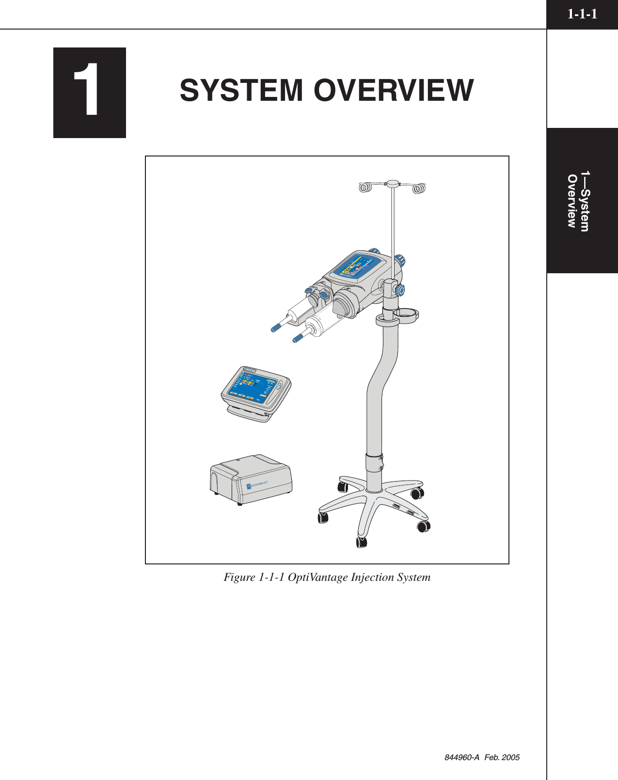


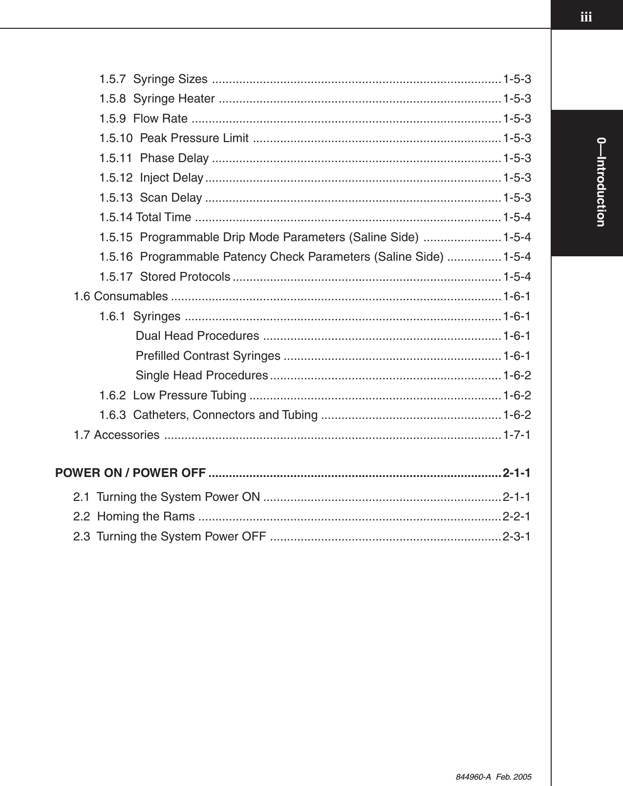
![844960-A Feb. 20051—SystemOverview1-4-11.4 FEATURES1.4.1 SAFETYThe OptiVantage has been designed to enhance the safety of both patient andoperator. Specific safety features include:Self-testing DesignWhen the OptiVantage is switched ON, it automatically performs a series ofpower-up tests to monitor the status of all systems. If a problem is detected, anappropriate message will appear in the system display. Also, during the enableprocess and during an injection, all necessary functions are constantly checked. Ifa fault is detected, the system will automatically shut down and an appropriatemessage will be displayed.Patency CheckTM FeaturePrior to the delivery of the main injection, a Patency Check--an injection of asmall volume of saline--can be performed to determine the integrity of the I.V.site.Timing BolusTM FeaturePrior to the delivery of the main injection, a Timing Bolus injection--an injectionof a small volume of contrast, followed by a small volume of saline--can bedelivered to the patient to determine the optimal scan delay needed to capture thecontrast agent in the area of interest.Drip Mode FeaturePrior to the delivery of the main injection, a Drip Mode injection--a low flow rateinjection of a small volume of saline--can be delivered to keep the fluid pathwayopen.OptiBolus® Feature (Optional)The OptiBolus feature is used to deliver an exponentially decaying flow rateinjection that optimizes the contrast usage and provides an extended period ofuniform enhancement of the area of interest. The End Flow Rate is automaticallycalculated by the OptiVantage and displayed only on the console Main screen.Pointing Powerhead Downward prior to Starting an InjectionAfter completion of the Enable sequence, the [Enable] key is only active aftertilting the powerhead to the downward position. Pointing the powerhead in thedownward position allows any trapped air in the syringe to move to the plungerend of the syringe, away from the syringe tip, possibly preventing it from beinginadvertently injected into the patient.](https://usermanual.wiki/Tyco-Healthcare-Mallkrodt/844003/User-Guide-698150-Page-25.png)
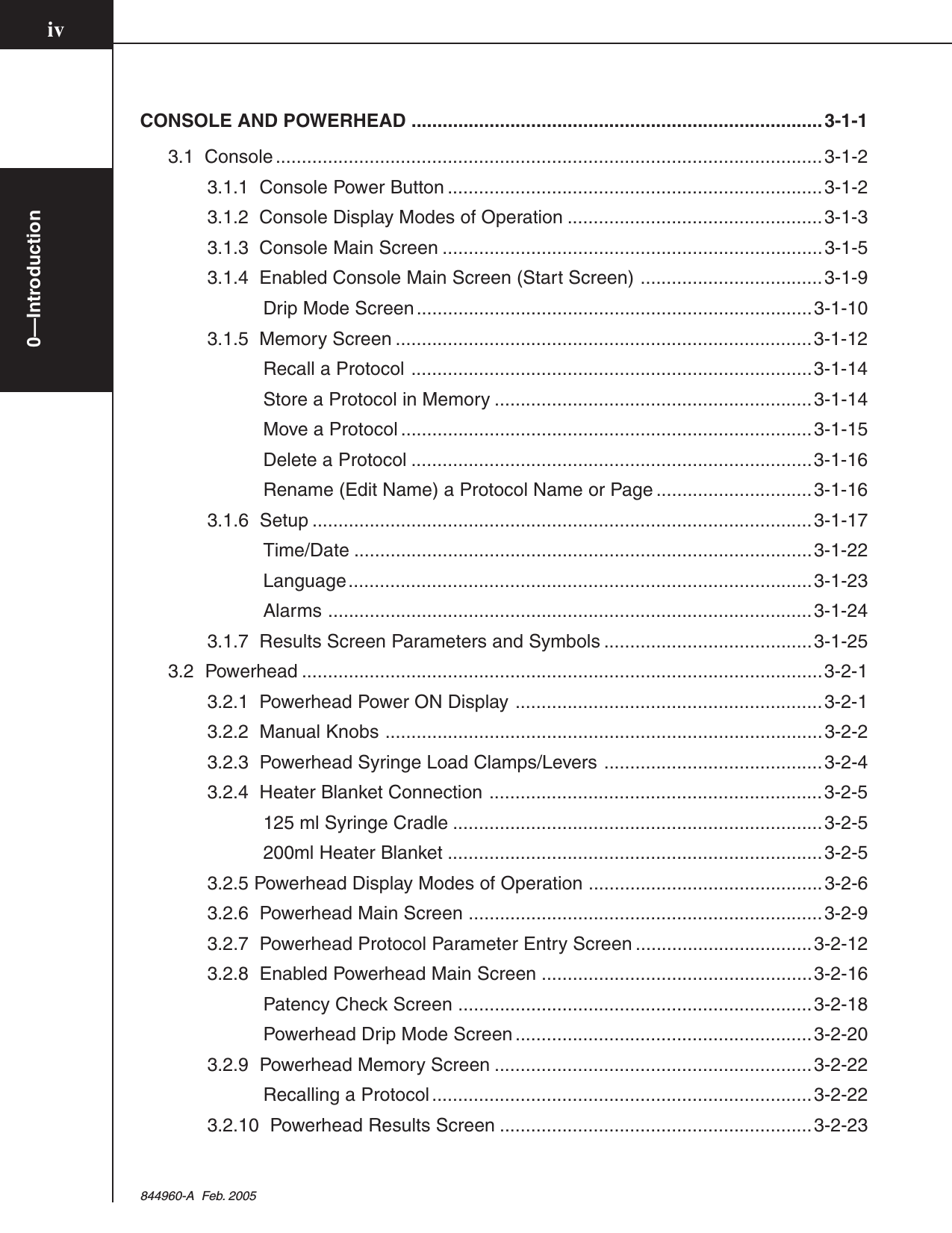
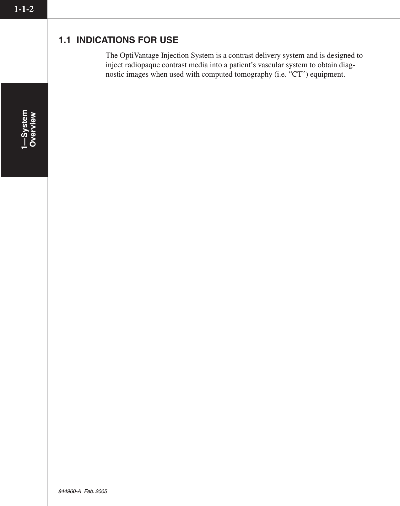
![844960-A Feb. 20051—SystemOverview1-4-2Start/Stop Key on PowerheadBecause the powerhead is near the patient during an injection, both the [Start] keyand the [Stop] key are integrated into the powerhead for starting or quickly stop-ping an injection.Remote Control OperationUse of the remote handswitch allows the operator to perform injections fromoutside the area of direct radiation.Electrically Isolated SyringeAll syringes are isolated from any electrical contact with the injector.Syringe ClaritySemitransparent syringes are used on the OptiVantage. Small air bubbles can beseen with careful observation.Positive Positioning of the PowerheadA preset friction device in the powerhead holds the syringe in the desired positionduring injection.Physical StabilityThe wide stance of the base of the pedestal assembly reduces the possibility oftipping. Two of the casters may be locked to prevent unwanted rolling and turning.1.4.2 OPERATOR CONVENIENCE FEATURESAuto-Fill FeatureThis feature is designed to automatically fill the syringe while minimizing theintroduction of air into the syringe. Upon loading a 200 ml syringe, the powerheadcan automatically fill to 25 ml at 4 ml/s, expell to 0 ml at 10 ml/s, then fill to theoperator programmed Auto-Fill Volume at 15 ml/s.](https://usermanual.wiki/Tyco-Healthcare-Mallkrodt/844003/User-Guide-698150-Page-26.png)


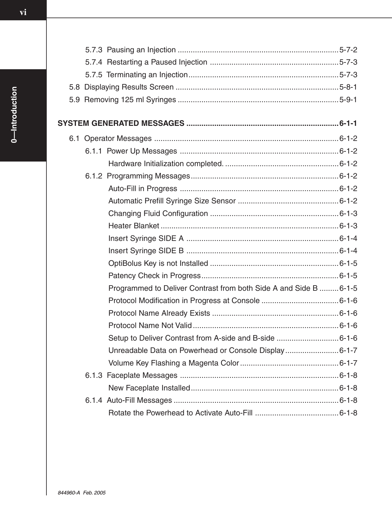
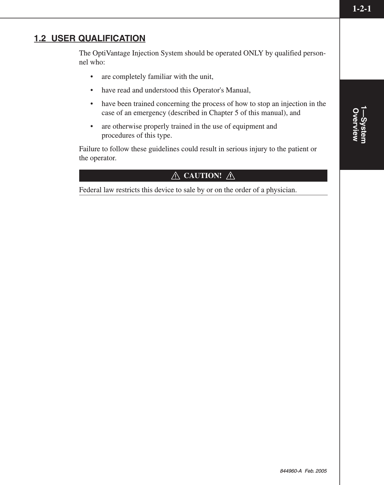
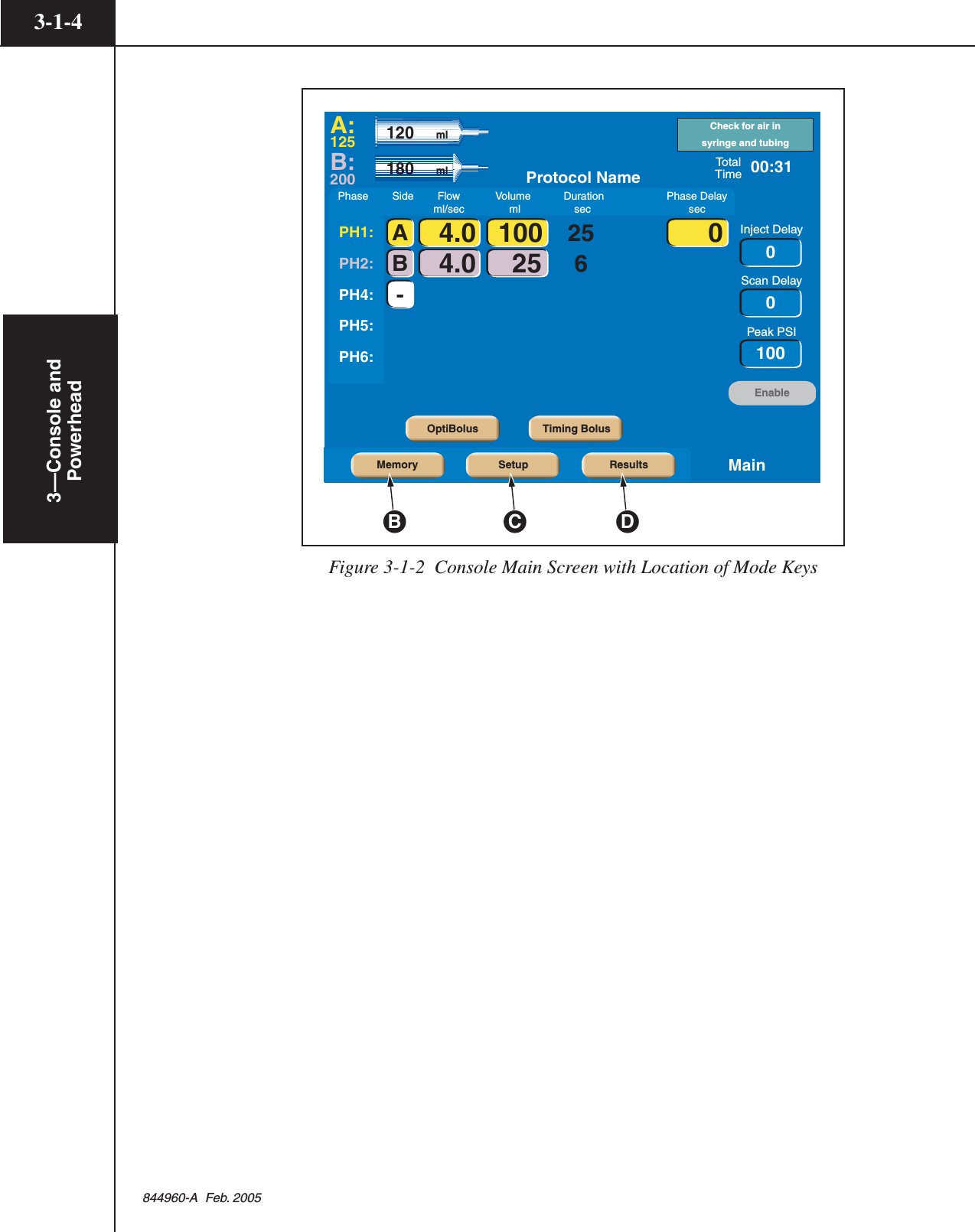
![3—Console and Powerhead3-1-3844960-A Feb. 20053.1.2 CONSOLE DISPLAY MODES OF OPERATIONRefer to Figure 3-1-2.Located along the lower portion of the console display are the following 4 keys:[Memory], [Setup], [Results] and [Main]. These keys allow access to their respec-tive modes of operation.Main Screen — Upon power-up, this screen is automatically displayed as shownin Figure 3-1-2. All protocol information needed by the injector is containedwithin the Main screen. To access the Main screen when displaying the Resultsscreen, Setup screen or Memory screen, press the active [Main] key located on thelower right-hand side of the screen.Enabled Main Screen — The Enabled Main screen allows for the delivery of themain protocol or a Drip Mode Injection.Memory Screen — All stored protocol information is located within the Memoryscreen. Accessing this screen allows the operator to recall, store, rename anddelete protocols. To access the Memory screen, press the [Memory] key Blocated on the lower portion of the screen.Setup Screen — Accessing this screen allows the operator to change the language,change the unit of measure for pressure, set the time, set parameter defaults,display the Alarm History, and access the service mode. To access the Setupscreen, press the [Setup] key C located on the lower portion of the screen.Results Screen — All information pertaining to the results of a delivered injectionis located within the Results screen. To access the Results screen, press the[Results] key D located on the lower portion of the screen.](https://usermanual.wiki/Tyco-Healthcare-Mallkrodt/844003/User-Guide-698150-Page-43.png)
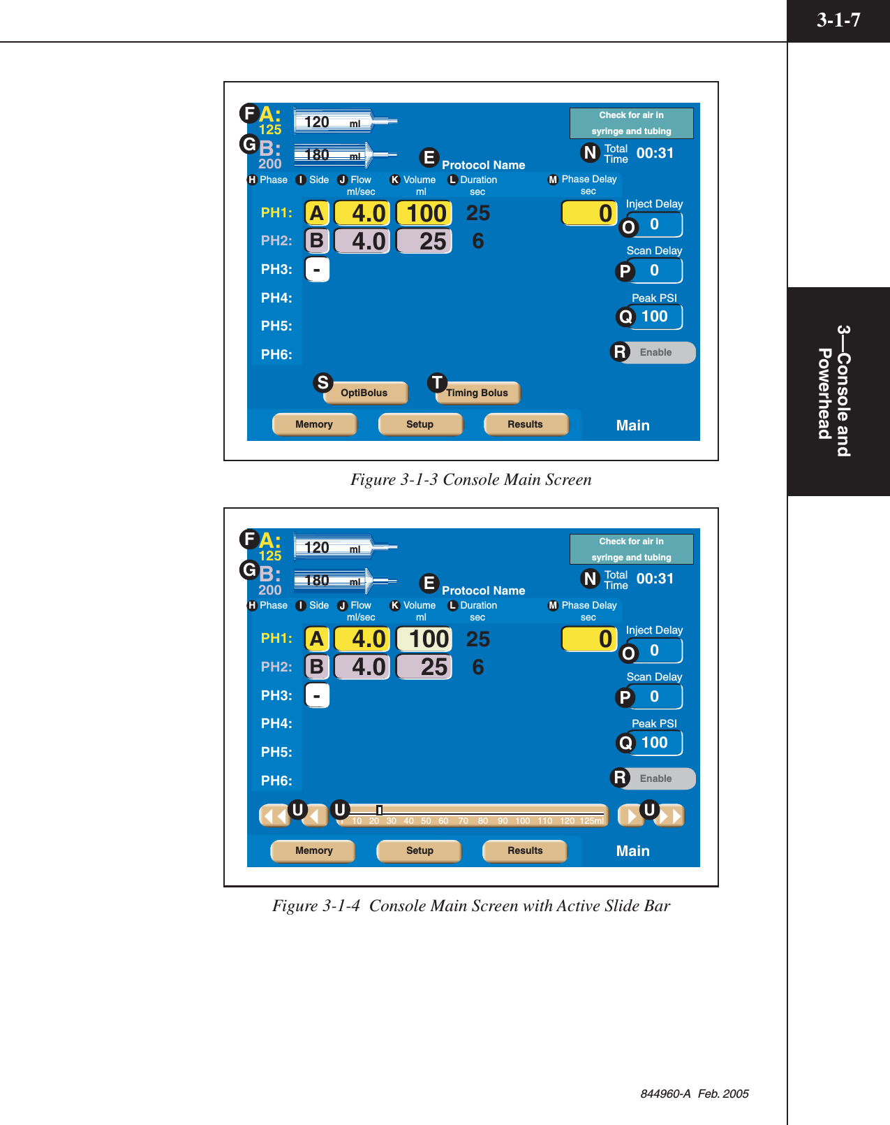
![3—Console and Powerhead3-1-5844960-A Feb. 20053.1.3 CONSOLE MAIN SCREENRefer to Figure 3-1-3 and Figure 3-1-4.Protocol Name E — The name of the protocol currently displayed on the MainScreen is located in this area of the screen. An asterisk located at the end of thename indicates that the displayed parameters have been modified and no longermatch the originally stored parameters.A: Syringe Size F — This information indicates the size of the syringe currentlyinstalled in the A-side of the powerhead. Note that contrast parameters are indi-cated by the color yellow. Saline parameters are indicated by the color purple.B: Syringe Size G — This information indicates the size of the syringe currentlyinstalled in the B-side of the powerhead. Note that contrast parameters are indi-cated by the color yellow. Saline parameters are indicated by the color purple.Phase H — Within a protocol, up to six phases can be input. “PH” is the abbre-viation of Phase.Side I — These keys toggle among the following symbols: [A], [B], [-].Pressing an [A] key will toggle the key to a [B] key, thus indicating injecting fromthe B-side. Pressing a [B] key will toggle the key to a white [-], indicating noinjecting for and past that phase. Pressing a white [-] key will toggle the key to a[A] key, thus indicating injecting from the A-side.Flow J — The values entered in this column indicate rate of delivery of thecontrast medium and saline during each respective phase. Flow is expressed inmilliliters/second.Volume K — The values entered in this column indicate the volume of contrastmedium and saline to be delivered during each respective phase. Volume isexpressed in milliliters.Duration L — The value in this column indicates the duration of a protocolphase (i.e., time to complete injection in seconds) based on the entered volumeand flow rate values. Duration is displayed in the nearest whole second.Phase Delay M — Phase Delay is a count down timer that delays the start of thenext phase. The next phase will start when the phase delay counter reaches0 (zero). Phase Delay is expressed in seconds. Phase Delay can also be set topause the injection. Access the Pause feature by scrolling past either the 0 (zero)lower limit or the 600 (six-hundred) upper limit.Total Time N — The Total Time field is an accumulation of all the calculatedDuration and Delay fields for all phases. The total time field starts counting upfrom 0 (zero) after the injector receives a start signal. Total time continues tocount after the injection is completed as long as the Results screen is displayed orup to 21 minutes. Total time is expressed in minutes:seconds.](https://usermanual.wiki/Tyco-Healthcare-Mallkrodt/844003/User-Guide-698150-Page-45.png)
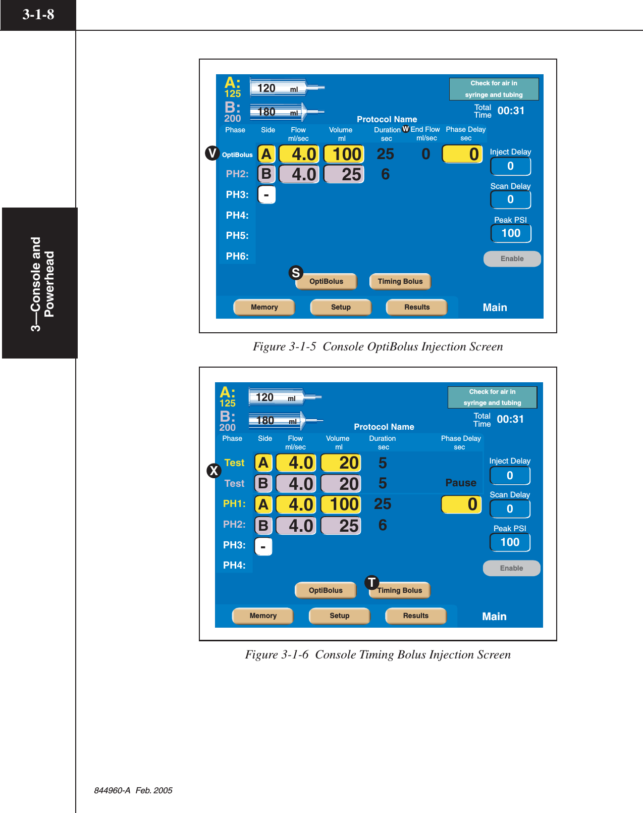
![3—Console andPowerhead3-1-6844960-A Feb. 2005Inject Delay O — Inject Delay is a count down timer that begins counting whenthe Start command is activated. The injection is started when the inject delaycounter reaches 0 (zero). If Inject Delay is greater than 0 (zero), Scan Delay isautomatically set to 0 (zero). Inject Delay is expressed in seconds.Scan Delay P — Scan Delay is a count down timer that begins counting whenthe Start command is activated and stops when the counter reaches 0 (zero). Thescan start signal will initiate once the timer reaches 0 (zero). If Scan Delay isgreater than 0 (zero), Inject Delay is automatically set to 0 (zero). Scan Delay isexpressed in seconds.Peak PSI/Peak KPA Q — The value set in this key indicates the maximum allow-able pressure that can occur during an injection. Pressure is expressed in eitherPSI or kPa. Refer to section 3.1.6 Setup Screen Parameters and Symbols for moreinformation about changing the unit of measure.Enable R — This key is only active when proper enabling sequence is fol-lowed and after the powerhead is tilted downward. Pressing the active[Enable] key “enables” the injector (displays the [Start] key) for delivery of aprotocol.OptiBolus (optional) S — This key is only active if a port-key is present at theOptiBolus port located on the rear of the power supply. Pressing this key allowsthe operator to program an OptiBolus injection. The OptiBolus Mode delivers anexponentially decaying flow rate injection that optimizes the contrast usage andprovides an extended period of uniform enhancement of the area of interest. Oncethe [Optibolus] key S is pressed, the screen shown in Figure 3-1-5 is displayed.Note the addition of the Optibolus symbol V to the left of the first phase alongwith the addition of End Flow Rate W. End Flow Rate W is a function of theOptibolus mode and is automatically calculated by the OptiVantage for the en-tered parameters and is displayed only on the console Main screen.Timing Bolus T — This key is only active if turned ON at the Setup Screen andwhen 4 or less phases are programmed in a protocol. Pressing this key allows theoperator to program a Timing Bolus injection. A Timing Bolus injection--aninjection of a small volume of contrast, followed by a small volume of saline--canbe delivered to the patient to determine the optimal scan delay needed to capturethe contrast agent in the are of interest. Once the [Timing Bolus] key T ispressed, the screen shown in Figure 3-1-6 is displayed. Note the addition of “Test”X to the left of the first and second phase.Change Parameter Values via the Slide Bar U — To change the value of a param-eter, select the desired parameter by touching its key. The key will highlight toindicate it is active and the slide bar will display at the bottom of the screen.Touch the slide bar at the value required, or use the left and right double arrows todecrease or increase the value. Use the left and right single arrows to decrease orincrease the value in smaller increments.](https://usermanual.wiki/Tyco-Healthcare-Mallkrodt/844003/User-Guide-698150-Page-46.png)
![3—Console and Powerhead3-1-9844960-A Feb. 20053.1.4 ENABLED CONSOLE MAIN SCREEN (START SCREEN)Refer to Figure 3-1-7.After pressing the active [Enable] key, the screen shown in Figure 3-1-7 is dis-played. From this screen, the operator can change parameters, program anOptiBolus injection, program a Timing Bolus injection, enter the Drip Mode, orstart the delivery of the protocol.Start Y — This key starts the delivery of the programmed protocol. For moreinformation about delivering injections, refer to Chapter 5.Drip Z — This key is active if turned ON at the Setup Screen and only displayedafter the [Enable] key is pressed. Pressing this key allows the operator to programa “drip” injection--a low flow rate injection of a small volume of saline deliveredto keep the fluid pathway open. Refer to Figure 3-1-8.Disable AA — This keys allows the injector to disable from the enabled mode.PH1:PH2:PH3:PH4:PH5:PH6:TotalTimeInject DelayScan DelayPeak PSI00:316254.0 100 04.0 25AB-A:125B:200120 ml10000Start180 mlProtocol NamePhase Side Flow Volume Duration Phase Delay ml/sec ml sec sec OptiBolus Timing BolusDisableDripAAZYFigure 3-1-7 Enabled Console Main Screen](https://usermanual.wiki/Tyco-Healthcare-Mallkrodt/844003/User-Guide-698150-Page-49.png)
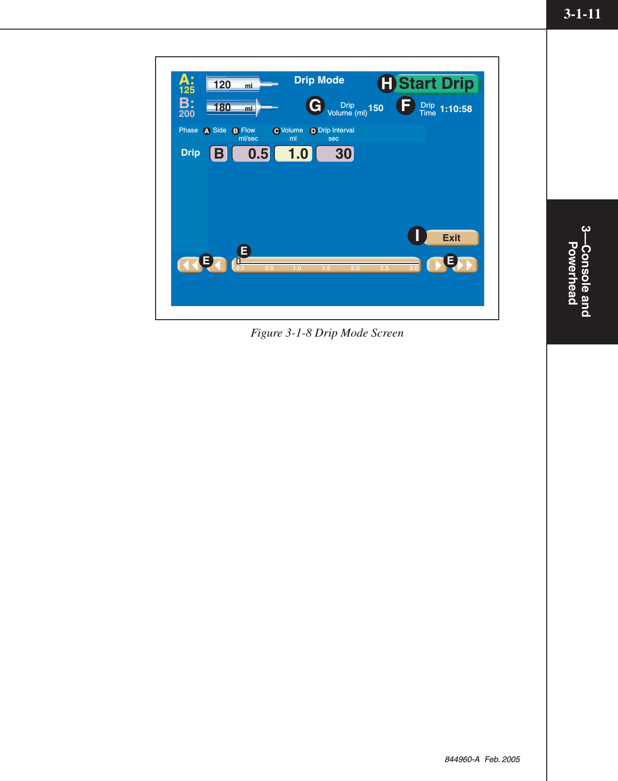
![3—Console andPowerhead3-1-10844960-A Feb. 2005Drip Mode ScreenRefer to Figure 3-1-8.The Drip Mode allows the injector to deliver a “drip” injection to keep the fluidpath open during patient set up and between injections of contrast. The Drip Modeis accessible from either the Console Enabled Main Screen or the PowerheadEnabled Main Screen.To access the Drip Mode screen as shown in Figure 3-1-8, press the [Drip] key Zlocated on the enabled Main screen (shown in Figure 3-1-7).Side A — The Drip injection can only be delivered from the saline side. (InFigure 3-1-8, the B-side is set up as the saline side.)Drip Mode Flow B — This value indicates rate of delivery of the saline. DripMode flow is expressed in milliliters/second.Drip Mode Volume C — This value indicates the volume of saline to be deliv-ered during each drip injection. Drip Mode volume is expressed in milliliters.Interval D — This value indicates the amount of time the injector pauses be-tween each delivery of drip injections. Drip Mode interval is expressed in seconds.Change Parameter Values via the Slide Bar E — To change the value of aparameter, select the desired parameter by touching its key. The key will highlightto indicate it is active and the slide bar will display at the bottom of the screen.Touch the slide bar at the value required, then use the left and right double arrowsto decrease or increase the value. Use the left and right single arrows to decreaseor increase the value in smaller increments.Drip Time F — Calculated automatically by the injector by using the pro-grammed Flow, Volume and Interval values, this value indicates the amount oftime the Drip Injection will require. Once the [Start Drip] key is pressed, the valuecounts down until it reaches zero. Once Drip Time reaches zero, an audible signalwill indicate to the operator that the Drip Injection is complete.Drip Volume G — Calculated automatically by the injector by subtracting theprogrammed Volume of the main protocol (saline side) from the syringe volume(saline side), this value indicates the amount of saline the Drip Injection caninject. Drip Volume is expressed in ml.Start Drip H — This key starts the drip injection. For more information aboutdelivering a drip injection, refer to Chapter 5.Exit I — This key disables the drip injection and displays the Enabled Mainscreen.](https://usermanual.wiki/Tyco-Healthcare-Mallkrodt/844003/User-Guide-698150-Page-50.png)
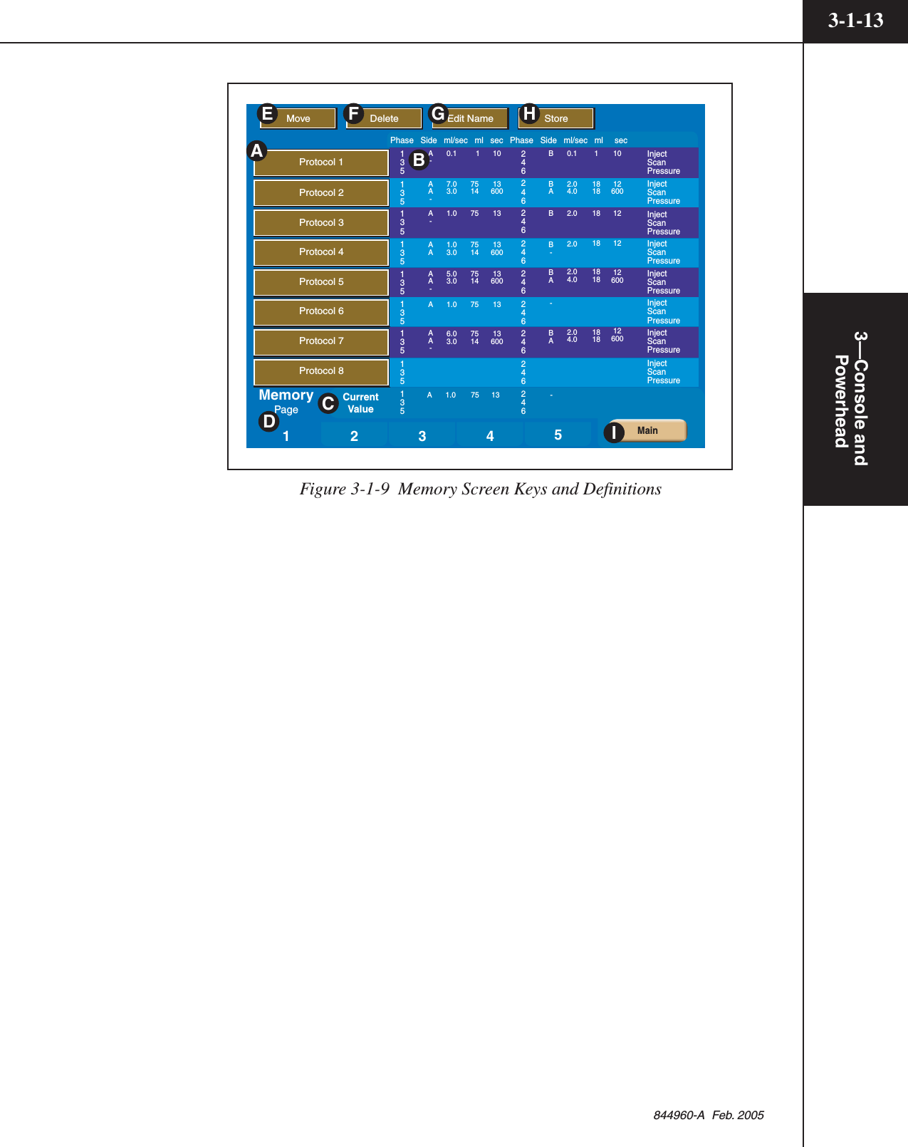
![3—Console andPowerhead3-1-12844960-A Feb. 20053.1.5 MEMORY SCREENRefer to Figure 3-1-9.NOTE: If password protection is ON, moving, deleting, renaming or storingprotocols is not permitted unless the correct password is entered.Memory Location A — The unit can store up to 40 six-phase protocols with 8protocols listed per page. Each protocol can have a name consisting of up to 20alpha-numeric characters. To display the protocol on the Main Screen, simplypress the Protocol’s corresponding key. OptiBolus protocols are indicated by the“OptiBolus” logo located on the key.Protocol Parameters B — Each protocol can contain up to six phases.Current Values C — The current values displayed on the Main screen are locatedin this area.Memory Page Number D — The memory screen contains five pages with eightprotocols listed per page.Move E — This key allows the operator to move a protocol into a different slotor onto a different page.Delete F — This key activates the delete feature. Press the [Delete] key, thenpress the key of the protocol to be deleted.Edit G — This key allows the operator to edit the name of a protocol.Store H — This key stores the current values into a protocol memory slot.Cancel (not shown) — This key is only displayed after pressing the [Move] key,the [Delete] key, the [Edit] key or the [Store] key and is used to cancel the feature.Main I — This key allows the operator to return to the Main screen.](https://usermanual.wiki/Tyco-Healthcare-Mallkrodt/844003/User-Guide-698150-Page-52.png)
![3—Console andPowerhead3-1-14844960-A Feb. 2005Recall a ProtocolRefer to Figure 3-1-9.1. Access the Protocol Memory menu by pressing the [Memory] key located onthe bottom of the console Main screen.2. Press the appropriate page (1, 2, 3, 4 or 5) D on which the Protocol is stored.3. Press the key A of the desired Protocol Name. The protocol will be immedi-ately displayed on both the powerhead display and the console display.Store a Protocol in MemoryRefer to Figure 3-1-9 and Figure 3-1-10. This feature is only accessible from theconsole.1. Enter all required parameters on the Main screen.2. Access the Protocol Memory menu by pressing the [Memory] key located onthe bottom of the console Main screen.3. Press the appropriate page (1, 2, 3, 4 or 5) D on which to store the Protocol.4. Press the [Store] key H. The display will prompt the user with “Selectmemory location.”5. Press the desired memory location key A. A keyboard will appear in order toname the protocol. Refer to Figure 3-1-10.6. Enter the desired name using the keyboard. Press the keyboard [Enter] key Jwhen finished. The protocol will be stored at the memory location selected.](https://usermanual.wiki/Tyco-Healthcare-Mallkrodt/844003/User-Guide-698150-Page-54.png)
![3—Console and Powerhead3-1-15844960-A Feb. 20054321MemoryPageMain5Move Delete Edit Name StoreProtocol 1Protocol 2Protocol 3Protocol 4Protocol 5Protocol 6Protocol 7Protocol 8Phase Side ml/sec ml sec Phase Side ml/sec ml sec101260012121260012600135135135135135135135135135246246246246246246246246246118181818181818180.12.04.02.02.02.04.02.04.0BBABB-BA-BA10136001313600136001313600 1751475751475147575140.17.03.01.01.03.05.03.01.06.03.0A-AA-A-AAAA-AAA-A 1.0 75 13 -CurrentValueInjectScanPressureInjectScan Pressure2.82.222683.3 53.3 4730Caps On Cancel Space <- Enter0 1 2 3 4 5 6 7 8 9Q W E R T Y U I O PA S D F G H J K L Z X C V B N MFigure 3-1-10 Memory KeyboardMove a ProtocolRefer to Figure 3-1-9. This feature is only accessible from the console.1. Access the Protocol Memory menu by pressing the [Memory] key located onthe bottom of the console Main screen.2. Press the appropriate page (1, 2, 3, 4 or 5) D on which the Protocol is stored.3. Press the [Move] keyE. The display will prompt the user with “Select proto-col to move.”4. Press the key of the protocol to be moved. The display will prompt the userwith “Select position to insert moved protocol.”5. Press the desired memory location key A onto which the Protocol is to berelocated. The protocols will be shifted upwards or downwards to accommo-date the new location of the moved protocol.](https://usermanual.wiki/Tyco-Healthcare-Mallkrodt/844003/User-Guide-698150-Page-55.png)
![3—Console andPowerhead3-1-16844960-A Feb. 2005Delete a ProtocolRefer to Figure 3-1-9. This feature is only accessible from the console.1. Access the Protocol Memory menu by pressing the [Memory] key located onthe bottom of the console Main screen.2. Press the appropriate page (1, 2, 3, 4 or 5) D on which the Protocol is stored.3. Press the [Delete] key F. The display will prompt the user with “Select proto-col to delete.”4. Press the key of the protocol to be deleted. The display will prompt the userwith “Are you sure?” Pressing the [Yes] key deletes the protocol frommemory. Pressing the [No] key returns you to the Memory screen withoutdeleting the protocol from memory.Rename (Edit Name) a Protocol Name or PageRefer to Figure 3-1-9 and Figure 3-1-10. This feature is only accessible from theconsole.1. Access the Protocol Memory menu by pressing the [Memory] key located onthe bottom of the console Main screen.2. Press the appropriate page (1, 2, 3, 4 or 5) D on which the Protocol is stored.3. Press the [Edit Name] keyG. The display will prompt the user with “Selectprotocol to rename.”4. Press the key of the protocol to be renamed and enter the new name using thedisplayed keyboard (shown in Figure 3-1-10). Press the keyboard[Enter] key J when finished. The protocol will be stored under the new nameat the same memory location.](https://usermanual.wiki/Tyco-Healthcare-Mallkrodt/844003/User-Guide-698150-Page-56.png)
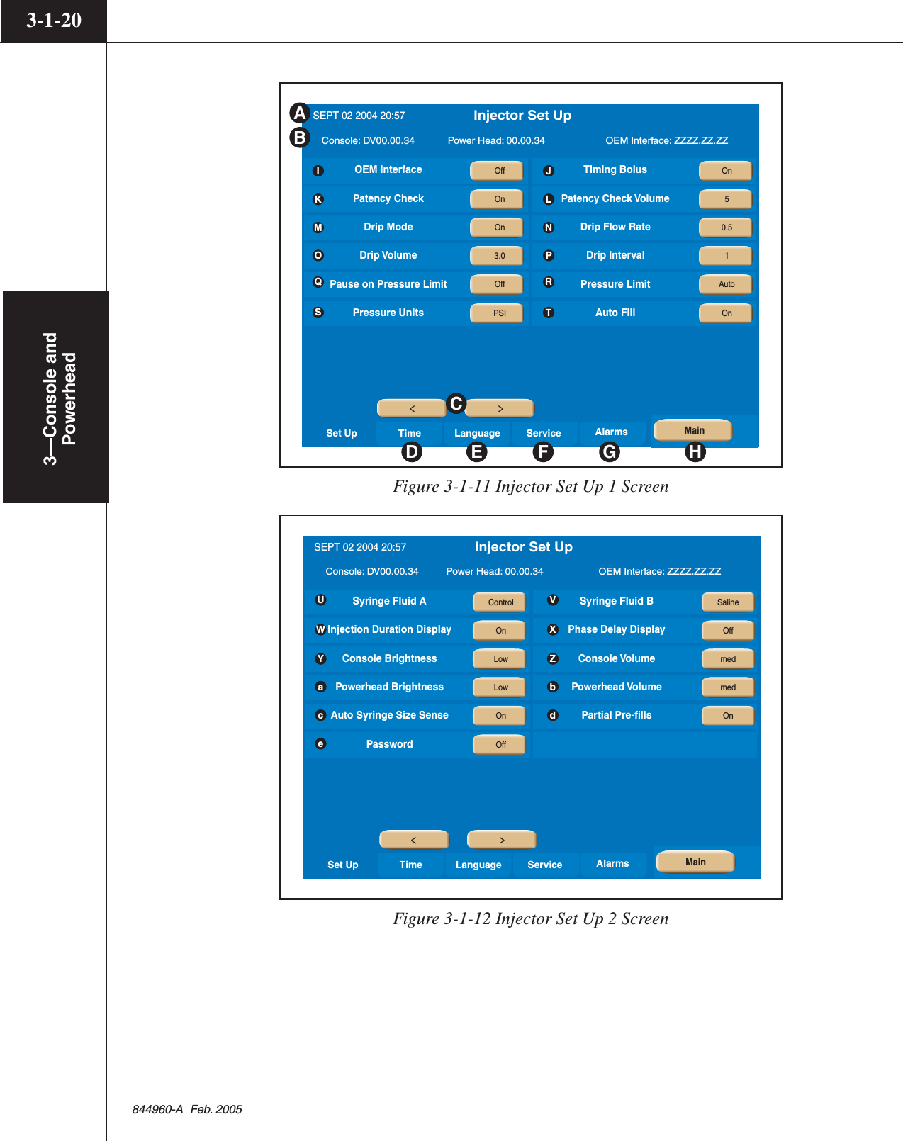
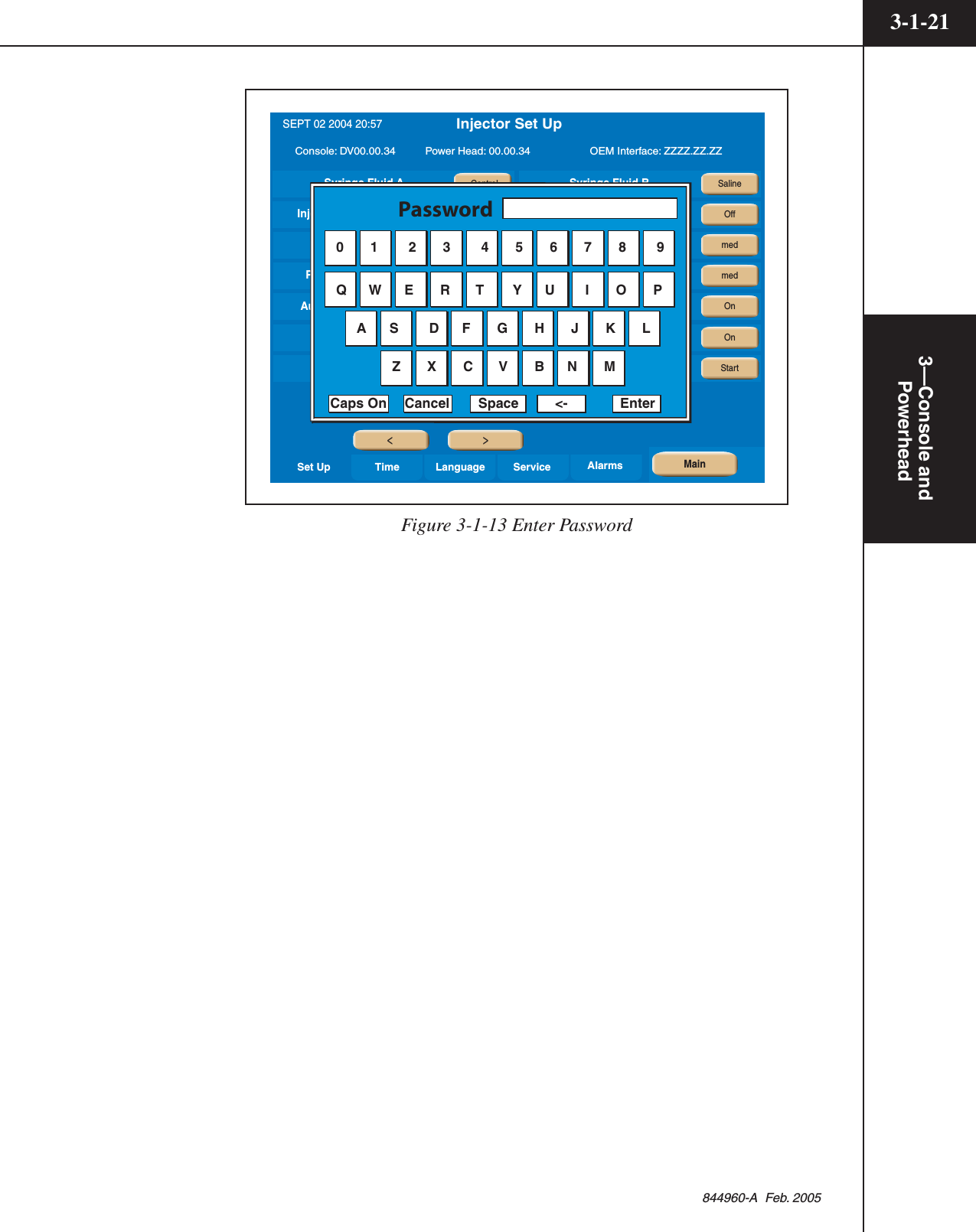
![3—Console and Powerhead3-1-17844960-A Feb. 20053.1.6 SETUPRefer to Figures 3-1-11 and 3-1-12.Access the Setup screens by pressing the [Setup] key ( B on Figure 3-1-2) locatedon the Main Screen of the Console. Note: The Setup Screen and its features arenot accessible from the Powerhead screen. Also, if password protection is ON,access to the Setup screens is not permitted unless the correct password is entered.The Setup Screen allows the operator to adjust injection parameters, set the timeand date, select the language, enter the service mode, and view the alarm historyof the injector. Use the [< , >] keys C to toggle between the two set up screens.Date and Time A — Indicates the Date and Time as set in item D.Software Versions B — Indicates the software installed in the console, power-head, and the current Scanner Interface software.[< , >] keys C — These keys allow the user to toggle between the two Set Upscreens as shown in Figure 3-1-11 and 3-1-12.[Time] key D — This key allows the user to set the time and date. Refer to Figure3-1-14.[Language] key E — This key allows the user to change the language of theinjector. Refer to Figure 3-1-15.[Service] key F — This key allows service personnel access to the servicescreens. Note: The service screens are only accessible through use of a servicekey. Refer to the Service Manual.[Alarm] key G — The injector’s alarm history is accessible through use of thiskey.[Main] key H — This key allows the user to exit the Set Up screens and return tothe Main Screen.OEM Interface I — Select On or Off. Selecting “On” allows the OEM Interfaceto exercise limited control over the injector. Selecting “Off” disables the OEMInterface.Timing Bolus J — Select either On or Off. If On is selected, a [Timing Bolus]key will be made available on the Main screen to deliver a “Timing Bolus” injec-tion to determine optimum image quality in order to determine the ideal scandelay.Patency Check K — Select either On or Off. If On is selected, a [Patency] keywill be made available (after the injector is enabled) on the Powerhead to inject asmall volume of saline at the maximum flow rate as the enabled protocol in orderto check patency of the I.V. site.](https://usermanual.wiki/Tyco-Healthcare-Mallkrodt/844003/User-Guide-698150-Page-57.png)
![3—Console andPowerhead3-1-18844960-A Feb. 2005Patency Check Volume L — The [Patency Check Volume] key allows the opera-tor to set a default value for the Patency Check injection.Drip Mode M — Select either On or Off. If On is selected, a [Drip Mode] keywill be made available (after the injector is enabled) to deliver a “drip” injection(series of small volumes of saline) to keep the fluid path open.Drip Flow Rate N — The [Drip Flow Rate] key allows the operator to set adefault Flow Rate value for the Drip Injection.Drip Volume O — The [Drip Volume] key allows the operator to set a defaultVolume value for the Drip Injection.Drip Interval P — The [Drip Interval] key allows the operator to set a defaultvalue for the delay between Drip Injections.Pause on Pressure Limit Q — Select either On or Off. Selecting “On” will causethe injector to automatically pause in the instance of a pressure limited injection.Selecting “Off” will allow the injector to continue injecting at a lower flow ratebut will also display a message giving the operator the ability to either pause orcontinue.Pressure Limit R — Select either Manual or Auto. Selecting “Manual” allows theoperator to input a value for Peak Pressure Limit on the Main screen. Selecting“Auto” allows the injector to calculate a default value based on the highest flowrate of the displayed protocol. However, this value can be updated by the operatoron the Main screen.Pressure Units S — Select either PSI or kPa.Auto-Fill T — Select either On or Off. If On is selected, the Auto-Fill feature isavailable to the operator to automatically fill a 200 ml syringe while minimizingthe introduction of air.Syringe Fluid A U — Select either Contrast or Saline to be used in the A-sidesyringe.Syringe Fluid B V — Select either Contrast or Saline to be used in the B-sidesyringe.Injection Duration Display W — Select either On or Off. Selecting Off removesthe Injection Duration value (time to complete injection in seconds) from theMain Screen.Phase Delay Display X — Select either On or Off. Selecting Off removes the[Phase Delay] key and its value from the Main Screen.Console Brightness (display) Y — Select between Low or High.Console Volume (display) Z — Select among Off, Low, Med or High.](https://usermanual.wiki/Tyco-Healthcare-Mallkrodt/844003/User-Guide-698150-Page-58.png)
![3—Console andPowerhead3-1-22844960-A Feb. 2005Time/DateRefer to Figure 3-1-14.Access the ability to set the Time and Date by pressing the [Time] key ( D inFigure 3-1-10) .Press the [Change Date] key i and/or the [Change Time] key j to update thedate and time. Use the [ ] keys k to select the desired date and time.After changing the Date and/or Time to the desired value, press the[Set Date] key l and/or the [Set Time] key m for the change to take effect.Service LanguageTimeSet UpNOV 14 2056 15:50 Console: DV00.00.34 Power Head: 00.00.34 OEM Interface: ZZZZ.ZZ.ZZ Alarms Injector Set UpSEPT 02 2004 20:57Service LanguageTimeSet UpNOV 14 2056 15:50 Console: DV00.00.34 Power Head: 00.00.34 OEM Interface: ZZZZ.ZZ.ZZ Alarms Injector Set UpSEPT 02 2004 20:57k>>MainSet Date Set Time>>MainChange Date Change TimeijlmFigure 3-1-14 Setting the Time/Date](https://usermanual.wiki/Tyco-Healthcare-Mallkrodt/844003/User-Guide-698150-Page-62.png)
![3—Console and Powerhead3-1-23844960-A Feb. 2005LanguageRefer to Figure 3-1-15.Select the Language from among the selections located under the [Language] key(F in Figure 3-1-11)Service LanguageTimeSet UpSpanishFrenchPortugueseEnglishGermanItalian Console: DV00.00.34 Power Head: 00.00.34 OEM Interface: ZZZZ.ZZ.ZZ Alarms Injector Set UpSEPT 02 2004 20:57>>MainOffOffOffOffOffOnFigure 3-1-15 Selecting the Language](https://usermanual.wiki/Tyco-Healthcare-Mallkrodt/844003/User-Guide-698150-Page-63.png)
![3—Console andPowerhead3-1-24844960-A Feb. 2005AlarmsRefer to Figure 3-1-16Display the Alarm History screen by pressing the [Alarm] key (G inFigure 3-1-11) . Pressing the [<, >] keys (n in Figure 3-1-16), displays the mostrecent Alarms (up to 24) (on the console screen only) along with the protocol’ssettings at the time of the alarm.MainProgrammed ProtocolPhase Side ml/sec ml sec Phase Side ml/sec ml secInjectScanPressure135246 Alarm Occured onJAN 1 1970 0:00Alarm HistoryAlarm - x0000Page 0Set Up Time Language Service AlarmsP1 = 0x0000 P2 = 0x0000 P3 = 0x0000 P4 = 0x0000 P5 = 0x0000 P6 = 0x0000OffLowOEM InterfacePatency Check VolumeDrip VolumePressure LimitSyringe Fluid APhase Delay DisplayPowerhead BrightnessPartial Pre-FillsOffContrastManual0.00MonitorOffOffTiming BolusDrip ModeDrip IntervalPressure UnitsSyringe Fluid BConsole BrightnessPowerhead VolumePasswordLowContrastPSI0OffOffOffPatency CheckDrip Flow RatePause On Pressure LimitAuto-FillInjection Duration DisplayConsole VolumeAuto Syrings Size SenseOffOffOffOff0.5Off>>nFigure 3-1-16 Alarm Screen](https://usermanual.wiki/Tyco-Healthcare-Mallkrodt/844003/User-Guide-698150-Page-64.png)
![3—Console and Powerhead3-1-25844960-A Feb. 20053.1.7 RESULTS SCREEN PARAMETERS AND SYMBOLSRefer to Figure 3-1-17 and 3-1-18The Results Screen is automatically displayed after the delivery of an injectionand only shows the achieved results of that injection. The Results screen is dis-played for either 21 minutes or until the [Main] key is pressed. Refer toFigure 3-1-17.Pressing the [Results] key ( D in Figure 3-1-2) , however, displays the results ofthe last 24 injections (on the console screen only) along with the protocol’s set-tings. Refer to Figure 3-1-18.](https://usermanual.wiki/Tyco-Healthcare-Mallkrodt/844003/User-Guide-698150-Page-65.png)
![3—Console andPowerhead3-1-26844960-A Feb. 2005Phase Side Flow Volume Duration ml/sec ml sec Phase DelaysecPH1:PH2:PH4:PH5:PH6:TotalTimeInject DelayScan DelayPeak PSI05:44625 04.0 1004.0 25AB-PressurePSI0 50 100 150 200 250 300A:125B:125 15 ml0050Injection Completed onNOV 14 2005 09:35Protocol NameResultsMain 20 mlFigure 3-1-17 Results Screen displayed after delivery of an InjectionMainProgrammed ProtocolAchieved ValuesPhase Side ml/sec ml sec Phase Side ml/sec ml secInjectScanPressureInjectScan Pressure135135246246 Injection Completed onResults HistoryPage 1OffLowOEM InterfacePatency Check VolumeDrip VolumePressure LimitSyringe Fluid APhase Delay DisplayPowerhead BrightnessPartial Pre-FillsOffContrastManual0.00MonitorOffOffTiming BolusDrip ModeDrip IntervalPressure UnitsSyringe Fluid BConsole BrightnessPowerhead VolumePasswordLowContrastPSI0OffOffOffPatency CheckDrip Flow RatePause On Pressure LimitAuto-FillInjection Duration DisplayConsole VolumeAuto Syrings Size SenseOffOffOffOff0.5Off>>Figure 3-1-18 Results Screen displayed after pressing the [Results] Key](https://usermanual.wiki/Tyco-Healthcare-Mallkrodt/844003/User-Guide-698150-Page-66.png)
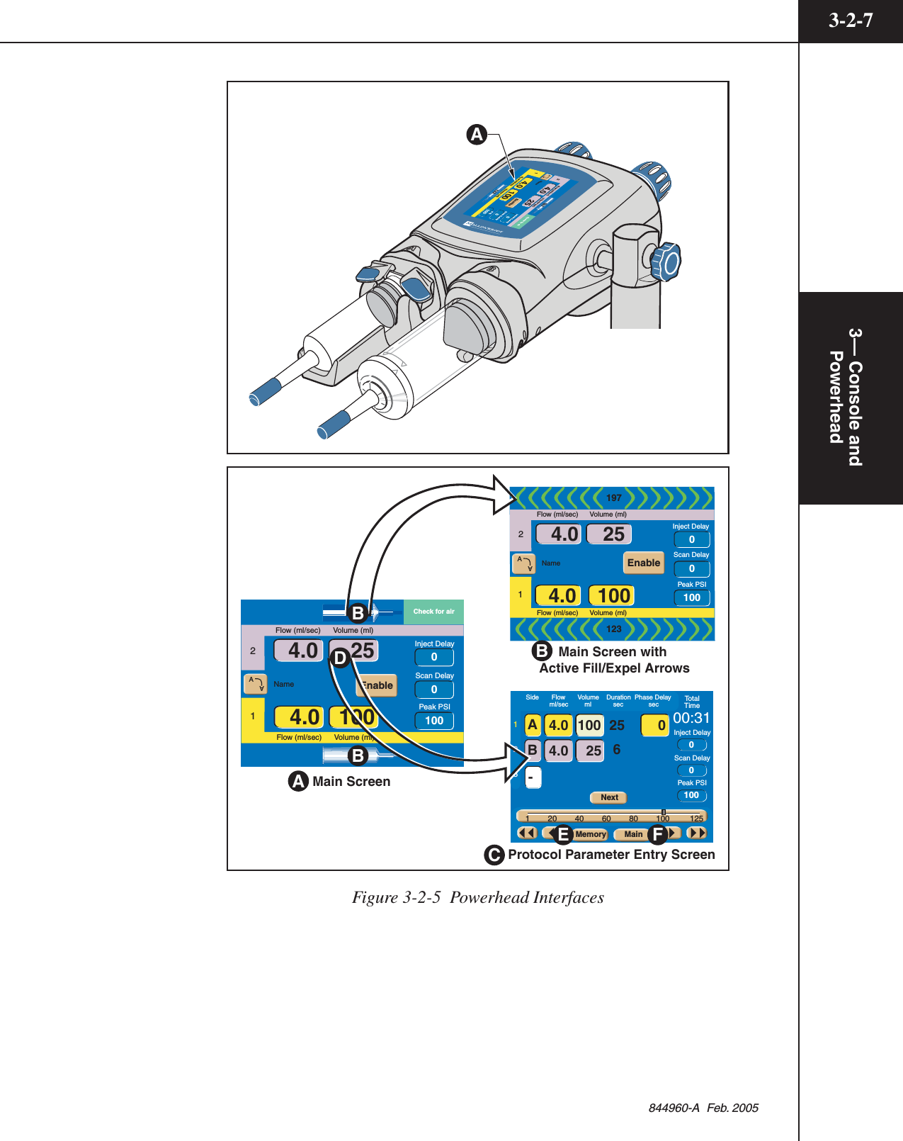
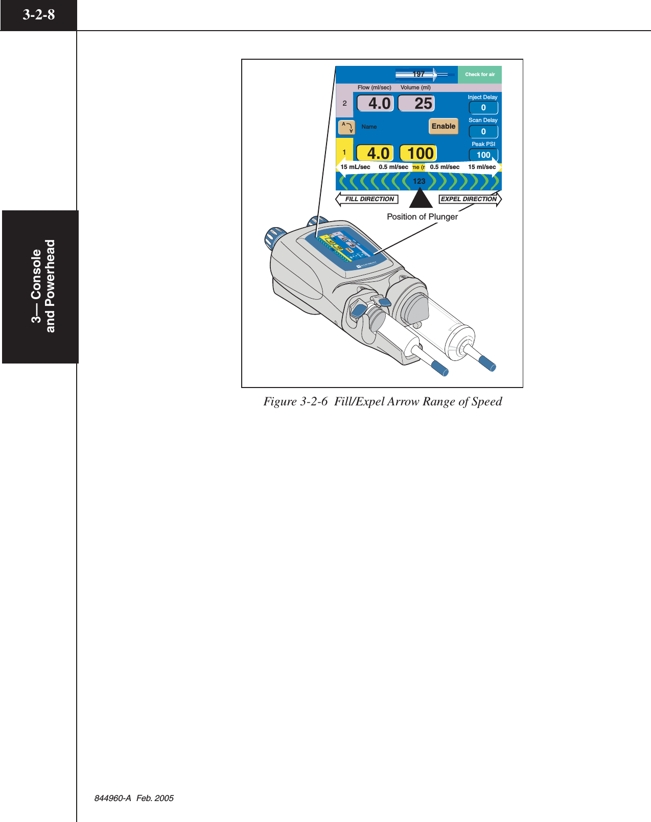
![3— Consoleand Powerhead3-2-6844960-A Feb. 20053.2.5 POWERHEAD DISPLAY MODES OF OPERATIONRefer to Figures 3-2-5 and Figure 3-2-6.Main Screen — The Powerhead Main screen A is shown in Figure 3-2-5. Onlythe first phase of the A-side and the B-side is displayed on the Powerhead Mainscreen. The complete protocol is displayed on the expanded Protocol ParameterEntry screen C.Fill/Expel Arrows — Two [Syringe] keys B, located in the upper and lowerportion of the Main screen, change to the fill/expel arrows as shown inFigure 3-2-5.Press on the [Syringe] key to activate the fill/expel arrows.Pressing on the active fill/expel arrows will retract/expel the ram at a rate that isproportional to the position touched in a range from 0.5 ml/sec to 15 ml/sec.Pressing the fill arrows for longer than 2 seconds will latch plunger movement.Once plunger movement has latched on, press anywhere on the powerhead displayto cease plunger movement. Refer to Figure 3-2-6. Note: The fill/expel arrows donot appear if the injector is enabled.Protocol Parameter Entry Screen C — To access the Protocol Parameter Entryscreen, press any parameter key D located on the Powerhead Main Screen. TheProtocol Parameter Entry screen allows modification of the parameters as well asaccess to the Memory screen. To access the Powerhead Main screen when dis-playing the Protocol Parameter Entry screen, press the [Main] key F located onthe lower portion of the screen.Enabled Main Screen — The Enabled Main screen allows for the delivery of themain protocol, a Patency Check, or a Drip Mode Injection.Memory Screen — All stored protocol information is located on the Memoryscreen. Displaying the Powerhead Memory screen allows the operator to onlyrecall protocols. Storing, renaming and deleting protocols is only available on theconsole Memory screen. To access the Powerhead Memory screen, press the[Memory] key E located on the lower portion of the Protocol Parameter Entryscreen as shown in Figure 3-2-5. When the Memory screen is displayed, press the[Main] key F to display the Main screen.](https://usermanual.wiki/Tyco-Healthcare-Mallkrodt/844003/User-Guide-698150-Page-72.png)
![3— Console andPowerhead3-2-9844960-A Feb. 20053.2.6 POWERHEAD MAIN SCREENRefer to Figure 3-2-7 and Figure 3-2-8.A-Side Syringe (mL)/A-side Fill/Expel Arrows A — This symbol indicates therelative position of the plunger in the syringe thus indicating how much fluid maybe in the A-side syringe. Pressing this key activates the A-side Fill/Expel arrows inorder to move the ram/plunger.B-Side Syringe (mL)/B-side Fill/Expel Arrows B — This symbol indicates therelative position of the plunger in the syringe thus indicating how much fluid maybe in the B-side syringe. Pressing this key activates the B-side Fill/Expel arrowsin order to move the ram/plunger.Fill/Expel arrows — Upon pressing either the A-side A or B-side B[Syringe] keys as shown in Figure 3-2-5, the fill/expel arrows are activated.Pressing on the fill/expel arrows will retract/expel the ram at a rate that is propor-tional to the position touched in a range from 0.1 ml/sec to 15 ml/sec. Pressing theretract fill arrows for longer than 2 seconds will latch ram retraction movement.Once ram retraction movement has latched on, the arrows will turn green and havea white background. Press anywhere on the powerhead display to cease latchedmovement. See Figure 3-2-6.1 (1st Phase) C — The 1 indicates the first phase of the protocol. Contrastparameters are indicated by the color yellow. Saline parameters are indicated bythe color purple. To access the remaining protocol information, press any param-eter key to display the Protocol Parameter Entry screen as shown in Figure 3-2-5.2 (2nd Phase) D — The 2 indicates the second phase of the protocol. If only aone phase protocol is programmed, the 2 will revert to a B to indicate the B-side.Contrast parameters are indicated by the color yellow. Saline parameters areindicated by the color purple. To access the remaining protocol information, pressany parameter key to display the Protocol Parameter Entry screen as shown inFigure 3-2-5.Display Orientation E — To view the powerhead display from either the A-sideor the B-side, the [Display Orientation] key allows the screen to flip as shown inFigure 3-2-8.Flow F — The values shown in this column indicate rate of delivery during eachrespective phase. When delivering a protocol, the values reflect the flow rate ofthe current phase being injected. Flow is expressed in milliliters/second.Volume G — The values entered in this column indicate the volume to be deliv-ered during each phase. When delivering a protocol, the values reflect the volumeof the current phase being injected. Volume is expressed in milliliters.](https://usermanual.wiki/Tyco-Healthcare-Mallkrodt/844003/User-Guide-698150-Page-75.png)
![3— Console andPowerhead3-2-11844960-A Feb. 2005Inject DelayScan DelayName12Flow (ml/sec) Volume (ml)Flow (ml/sec) Volume (ml)Peak PSI00100Check for air1231974.0 1004.0 25 JKLMFGFGHDCABAAEnableIEFigure 3-2-7 Powerhead Display Main Screen-4.01004.025Inject DelayScan DelayName12Flow (ml/sec) Volume (ml) Flow (ml/sec) Volume (ml) PSI10000AAEnable197Inject DelayScan DelayName12Flow (ml/sec) Volume (ml)Flow (ml/sec) Volume (ml)PSI00100AAEnable197Check for air123Check for air123Inject DelayScan DelayName12Flow (ml/sec) Volume (ml) Flow (ml/sec) Volume (ml) Peak PSI001000.1-254.0Check for air1971231004.04.04.010025Inject DelayScan DelayName12Flow (ml/sec) Volume (ml)Flow (ml/sec) Volume (ml)Peak PSI00100Check for air1231974.0 1004.0 25A - SIDE VIEW B - SIDE VIEWAAEnableAAEnableEEFigure 3-2-8 A-side Display or B-side Display usingthe [Display Orientation] Key.](https://usermanual.wiki/Tyco-Healthcare-Mallkrodt/844003/User-Guide-698150-Page-77.png)
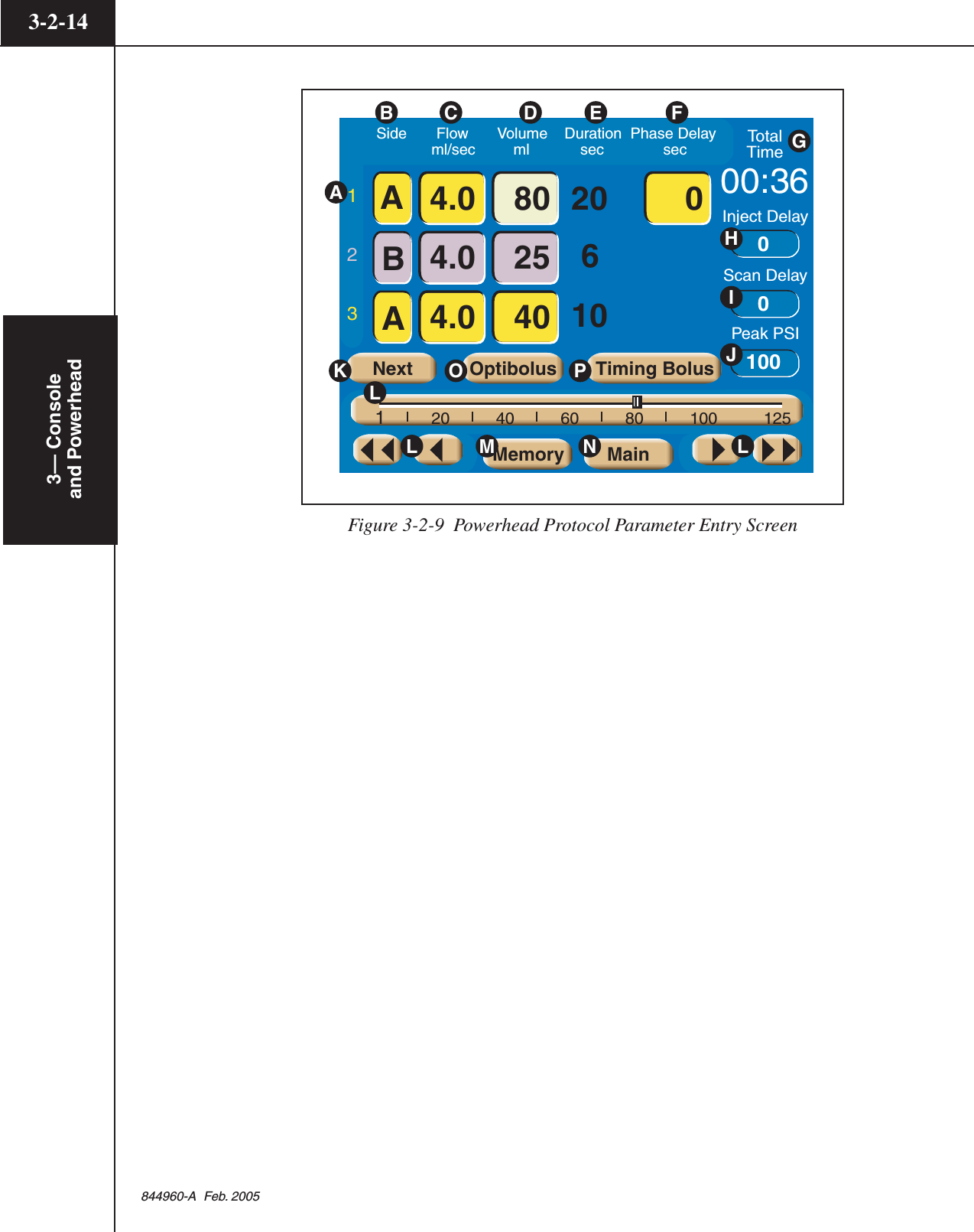
![3— Consoleand Powerhead3-2-12844960-A Feb. 20053.2.7 POWERHEAD PROTOCOL PARAMETER ENTRY SCREENRefer to Figure 3-2-9.All protocol information needed by the injector is contained within the expandedProtocol Parameter Entry screen. The Protocol Parameter Entry screen allows theparameters to be modified via the slide bar. To access this screen, press anyparameter key located on the Main Screen as shown in Figure 3-2-5.Phase A — Within a protocol, up to six phases can be input. Press the [Next]key K to view the next 3 phases.Side B — These keys toggle among the following symbols: [A], [B], [-].Pressing an [A] key will toggle the key to a [B] key, thus indicating injecting fromthe B-side. Pressing a [B] key will toggle the key to a white [-], indicating noinjecting for and past that phase. Pressing a white [-] key will toggle the key to a[A] key, thus indicating injecting from the A-side.Flow C — The values entered in this column indicate rate of delivery duringeach respective phase. Flow is expressed in milliliters/second.Volume D — The values entered in this column indicate the volume to be deliv-ered during each respective phase. Volume is expressed in milliliters.Duration E — The value in this column indicates the duration of an injection(i.e., time to complete injection in seconds) based on the previously enteredvolume and flow rate values. Duration is displayed in the nearest whole second.Phase Delay F — Phase Delay is a count down timer that delays the start of thenext phase. The next phase will start when the phase delay counter reaches0 (zero). Phase Delay is expressed in seconds. Phase Delay can also be set topause the injection. Access the Pause feature by scrolling past either the 0 (zero)lower limit or the 600 (six-hundred) upper limit.Total Time G — The Total Time field is an accumulation of all the calculatedDuration and input Phase Delay fields for all phases. After the [Start] key ispressed, the total time field starts counting from 0 and continues to count after theinjection is completed as long as the Results screen is displayed or up to 21minutes. Total time is expressed in minutes:seconds.Inject Delay H — Inject Delay is a count down timer that begins counting whenthe [Start] key is pressed. When Inject Delay reaches 0 (zero), the injection isstarted. If Inject Delay is set with a value greater than 0 (zero), Scan Delay isautomatically set to 0 (zero). Inject Delay is expressed in seconds.Scan Delay I — Scan Delay is a count down timer that begins counting whenthe [Start] key is pressed. The scan start signal will initiate once the timer reaches0 (zero). If Scan Delay is set with a value greater than 0 (zero), Inject Delay isautomatically set to 0 (zero). Scan Delay is expressed in seconds.](https://usermanual.wiki/Tyco-Healthcare-Mallkrodt/844003/User-Guide-698150-Page-78.png)
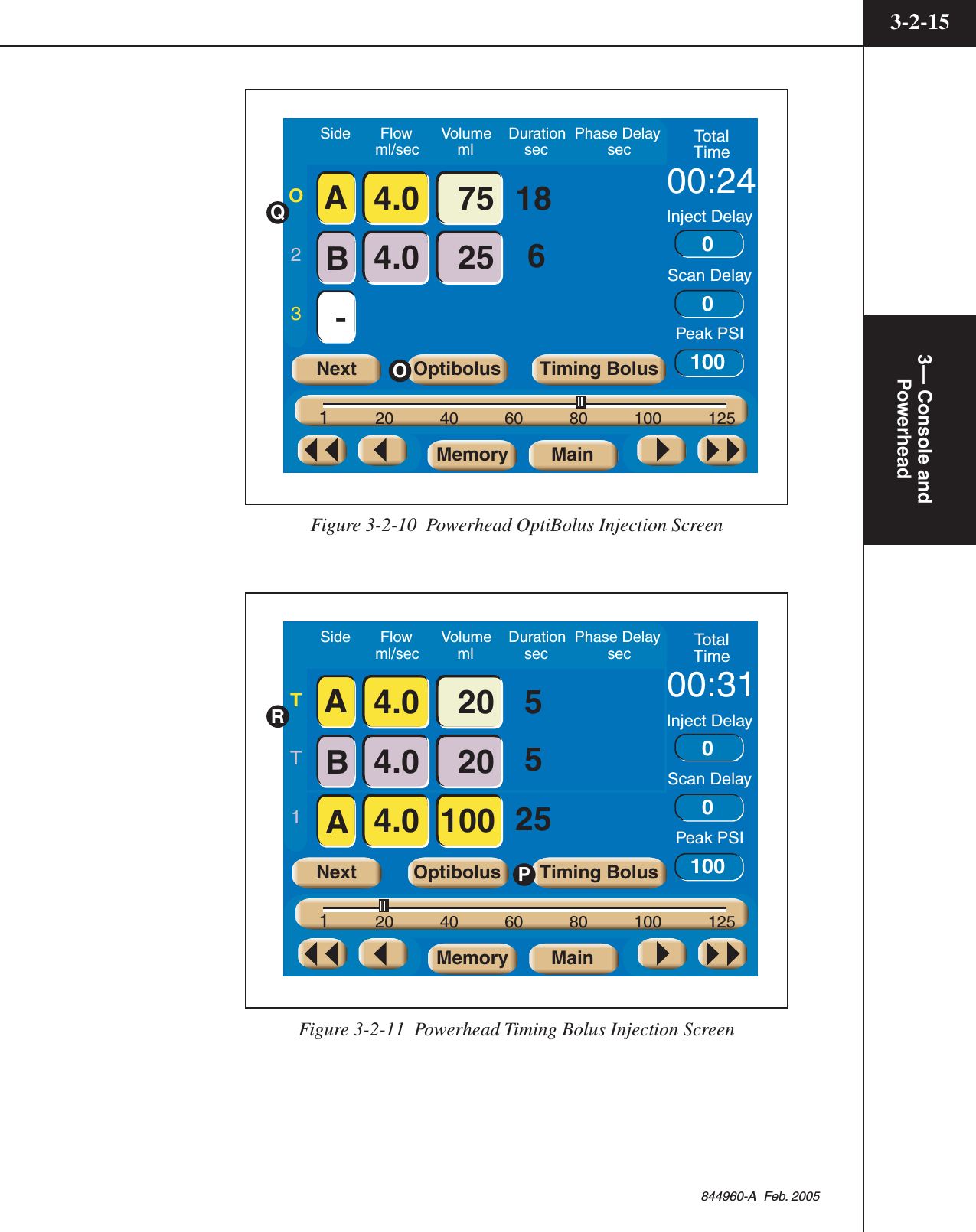
![3— Console andPowerhead3-2-13844960-A Feb. 2005Peak PSI J — The value set in this key indicates the maximum allowablepressure that can occur during an injection. Pressure is expressed in either PSI orkPa. Refer to section 3.1.5 Setup Screen Parameters and Symbols for moreinformation about changing the unit of measure.Next K — This key is only active when more than 3 phases exist on the ProtocolParameter Entry screen. Pressing this key displays the next 3 phases of the proto-col. The key will then toggle to a [Previous] key to allow access to the first 3phases of the protocol.Change Parameter Values via the Slide Bar L — To change the value of aparameter, select the desired parameter by touching its key. The key will highlightto indicate it is active and the slide bar will appear at the bottom of the screen.Touch the slide bar at the value required, then use the left and right double arrowsto decrease or increase the value. Use the left and right single arrows to decreaseor increase the value in smaller increments.Memory M — All stored protocol information is located within the Memoryscreen. Accessing this screen allows the operator to recall protocols. To access theMemory screen, press the [Memory] key located on the lower portion of thescreen. For more information, refer to the section Powerhead Memory Screen inthis chapter.Main N — Pressing this key displays the Powerhead Main Screen.OptiBolus (optional) O — This key is only active if a port-key is present at theOptiBolus port located on the rear of the power supply. Pressing this key allowsthe operator to program an OptiBolus injection. The OptiBolus Mode delivers anexponentially decaying flow rate injection that optimizes the contrast usage andprovides an extended period of uniform enhancement of the area of interest. Oncethe [Optibolus] key O is pressed, the screen shown in Figure 3-2-10 is displayed.Note the addition of “O” (OptiBolus) Q to the left of the first phase. End FlowRate is a function of the Optibolus mode and is automatically calculated by theOptiVantage for the entered parameters and is displayed only on the console Mainscreen.Timing Bolus P — This key is only active if turned ON at the Setup Screen andwhen 4 or less phases are programmed in a protocol. Pressing this key allows theoperator to program a Timing Bolus injection. A Timing Bolus injection--aninjection of a small volume of contrast, followed by a small volume of saline--canbe delivered to the patient to determine the optimal scan delay needed to capturethe contrast agent in the are of interest. Once the [Timing Bolus] key P ispressed, the screen shown in Figure 3-2-11 is displayed. Note the addition of “T”(Timing Bolus) R to the left of the first and second phase.](https://usermanual.wiki/Tyco-Healthcare-Mallkrodt/844003/User-Guide-698150-Page-79.png)
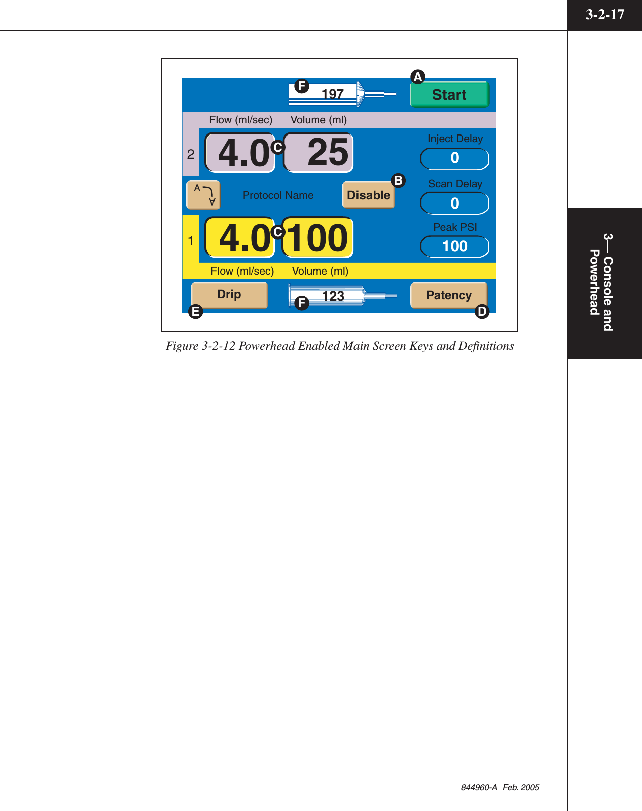
![3— Consoleand Powerhead3-2-16844960-A Feb. 20053.2.8 ENABLED POWERHEAD MAIN SCREENRefer to Figure 3-2-12.Once the [Enable] key is pressed, the Powerhead Main screen displays anEnabled screen as shown in Figure 3-2-12.Start A — Pressing the [Start] key begins the delivery of the protocol. This key isfunctionally interchangeable with both the [Stop] key and the [Start] key on theconsole and the optional Handswitch.Disable B —The [Disable] key disables the enabled injector.Protocol Parameters C — The protocol parameter entry keys are active and canbe changed as needed without disabling the injector.Patency D — This key is only active if turned ON at the Setup Screen. The[Patency] key is available to deliver a Patency Check--an injection of a smallvolume of saline--to determine the integrity of the I.V. site. Refer toFigure 3-2-11.Drip E — This key is only active if turned ON at the Setup Screen. The [Drip]key is available to deliver a Drip Mode Injection--a low flow rate injection of asmall volume of saline--to keep the fluid pathway open. Refer to Figure 3-2-14.A-Side Syringe (mL) and B-Side Syringe (mL) F — These symbols indicate therelative position of the plunger in the syringe thus indicating how much fluid maybe in the syringes. Once the injector is enabled, the fill/expel arrows will notappear when the A-side Syringe symbol or the B-side Syringe symbol is pressed.](https://usermanual.wiki/Tyco-Healthcare-Mallkrodt/844003/User-Guide-698150-Page-82.png)
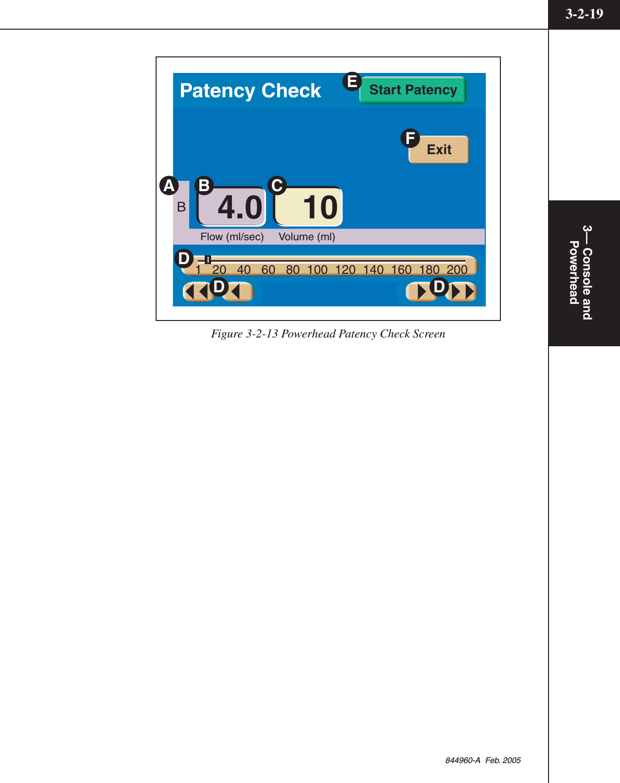
![3— Consoleand Powerhead3-2-18844960-A Feb. 2005Patency Check ScreenRefer to Figure 3-2-13.Prior to the delivery of the main injection, a Patency Check--an injection of asmall volume of saline--can be performed to determine the integrity of the I.V.site. The Patency Check feature is only accessible from the Powerhead EnabledMain Screen.To access the Patency Check screen as shown in Figure 3-2-13, press the[Patency] key D located on the Powerhead Enabled Main screen as shown inFigure 3-2-12.B (side) A — Patency check can only be delivered from the saline side. (InFigure 3-2-13, the B-side is set up as the saline side.)Patency Check Flow B — This value indicates rate of delivery of the saline.Patency check flow rate, expressed in milliliters/second, will automatically be setto the greatest value occurring in the enabled protocol. The value can be modifiedby the operator.Patency Check Volume C — This value indicates the volume of saline to bedelivered. Patency check volume, expressed in milliliters, is initially set to thedefault value as defined in the Set Up screen. The value can be modified by theoperator. If the value is set for an amount that compromises the enabled protocol,the [Patency Check Volume] key background wiil flash a magenta color and the[Start Patency] key will be removed from the screen.Change Parameter Values via the Slide Bar D — To change the value of aparameter, select the desired parameter by touching its key. The key will highlightto indicate it is active and the slide bar will display at the bottom of the screen.Touch the slide bar at the value required, then use the left and right double arrowsto decrease or increase the value. Use the left and right single arrows to decreaseor increase the value in smaller increments.Start Patency E — This key starts the patency check injection. For more infor-mation about delivering a patency check injection, refer to Chapter 5.Exit F — This key disables the patency check screen and displays the EnabledMain screen.](https://usermanual.wiki/Tyco-Healthcare-Mallkrodt/844003/User-Guide-698150-Page-84.png)
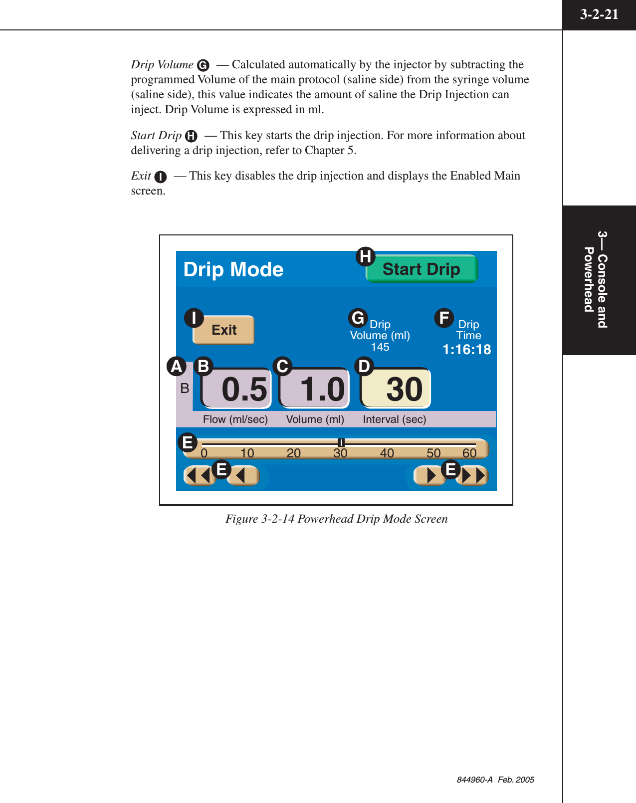
![3— Consoleand Powerhead3-2-20844960-A Feb. 2005Powerhead Drip Mode ScreenRefer to Figure 3-2-14.The Drip Mode allows the injector to deliver a “drip” injection to keep the fluidpath open during patient set up and between injections of contrast. The Drip Modeis accessible from either the Console Enabled Main Screen or the PowerheadEnabled Main Screen.To access the Drip Mode screen as shown in Figure 3-2-14, press the[Drip] key E located on the Enabled Main screen as shown in Figure 3-2-12.Side A — The Drip injection can only be delivered from the saline side. (InFigure 3-2-14, the B-side is set up as the saline side.)Drip Mode Flow B — This value indicates rate of delivery of the saline. DripMode flow is expressed in milliliters/second. The value can be modified by theoperator.Drip Mode Volume C — This value indicates the volume of saline to be deliv-ered during each drip injection. Drip Mode volume is expressed in milliliters. Thevalue can be modified by the operator. If the value is set for an amount that com-promises the enabled protocol, the [Drip Mode Volume] key background wiil flasha magenta color and the [Start Drip] key will be removed from the screen.Interval D — This value indicates the amount of time the injector pauses be-tween each delivery of drip injections. Drip Mode interval is expressed in seconds.Change Parameter Values via the Slide Bar E — To change the value of aparameter, select the desired parameter by touching its key. The key will highlightto indicate it is active and the slide bar will display at the bottom of the screen.Touch the slide bar at the value required, then use the left and right double arrowsto decrease or increase the value. Use the left and right single arrows to decreaseor increase the value in smaller increments.Drip Time F — Calculated automatically by the injector by using the pro-grammed Flow, Volume and Interval values and the Drip Volume, this valueindicates the amount of time the Drip Injection will require. Once the [Start Drip]key is pressed, the value counts down until it reaches zero. Once Drip Timereaches zero, an audible signal will indicate to the operator that the Drip Injectionis complete.](https://usermanual.wiki/Tyco-Healthcare-Mallkrodt/844003/User-Guide-698150-Page-86.png)
![3— Consoleand Powerhead3-2-22844960-A Feb. 20053.2.9 POWERHEAD MEMORY SCREENRefer to Figure 3-2-15.Memory Location A — Eight protocols are listed per page. Each protocol canhave a name consisting of up to 20 alpha-numeric characters. OptiBolus protocolsare indicated by the “OptiBolus” logo located on the key.Protocol Parameters B — Each protocol can contain up to six phases. Once aprotocol key is highlighted, the protocol parameters are displayed in this area.Memory Page Number C — The memory screen contains five pages with eightprotocols listed per page.Main D — Pressing this key displays the Powerhead Main screen.Recalling a Protocol1. Access the Protocol Memory menu by pressing the [Memory] key located onthe bottom of the powerhead Main screen.2. Press the appropriate page (1, 2, 3, 4 or 5) on which the Protocol is stored.3. Press the Protocol’s corresponding key to highlight E, then press the [Select]key F. The protocol will be immediately displayed on both the powerheaddisplay and the console display.4321 5Phase Side ml/sec ml sec Phase Side ml/sec ml sec 135246251004.0A-6254.0B-proto1proto2proto3AEBCMainDSelectFFigure 3-2-15 Powerhead Memory Screen Keys and Definitions](https://usermanual.wiki/Tyco-Healthcare-Mallkrodt/844003/User-Guide-698150-Page-88.png)
![3— Console andPowerhead3-2-23844960-A Feb. 20053.2.10 POWERHEAD RESULTS SCREENRefer to Figure 3-2-16.The Results Screen as shown in Figure 3-2-16 is automatically displayed after thedelivery of an injection and only shows the achieved results of that injection. TheResults screen is displayed for either 21 minutes or until the [Main] key ispressed.TotalTimeScan DelayPeak PSI05:44 Side Flow Volume Phase Delay12345604.0 1004.0 25AB-3 500ResultsInjection CompleteFeb 3 2005 9:4820MainFigure 3-2-16 Results Screen displayed after delivery of an Injection](https://usermanual.wiki/Tyco-Healthcare-Mallkrodt/844003/User-Guide-698150-Page-89.png)

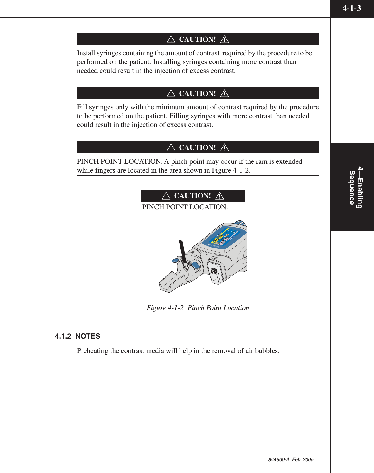
![4-1-14—EnablingSequence844960-A Feb. 20054ENABLINGSEQUENCEThis chapter discusses the proper techniques for loading syringes, filling sy-ringes, purging air from both the syringe and tubing, and priming the tubing.4.1 ENABLING SEQUENCERefer to Figure 4-1-1.The [Enable] key is only active when:1. a new syringe(s) is loaded2. the syringe is filled (200 ml only)3. the powerhead is tilted up and air is purged from both syringes (plunger mustmove forward to expel a minimum of 1 (one) ml of contrast/saline)4. the powerhead is rotated at least 30° below horizontal5. there is sufficient volume in the syringes to perform the programmed injection.Inject DelayLiver ExaminationABFlow (ml/sec) Volume (ml)Flow (ml/sec) Volume (ml)73AA1584.04.0 83Scan DelayPeak PSI1580020Enable1-0.11--Inject DelayScan DelayName12Flow (ml/sec) Volume (ml) Flow (ml/sec) Volume (ml) PSI000AAEnableCheck for air50502BFill Volume (ml)200Auto FillStart Auto Fill43Inject DelayScan DelayName1Flow (ml/sec) Volume (ml) Peak PSI0000.1 10.1-10.1125AAEnable2Flow (ml/sec) Volume (ml) 120Figure 4-1-1 Enabling Sequence](https://usermanual.wiki/Tyco-Healthcare-Mallkrodt/844003/User-Guide-698150-Page-91.png)

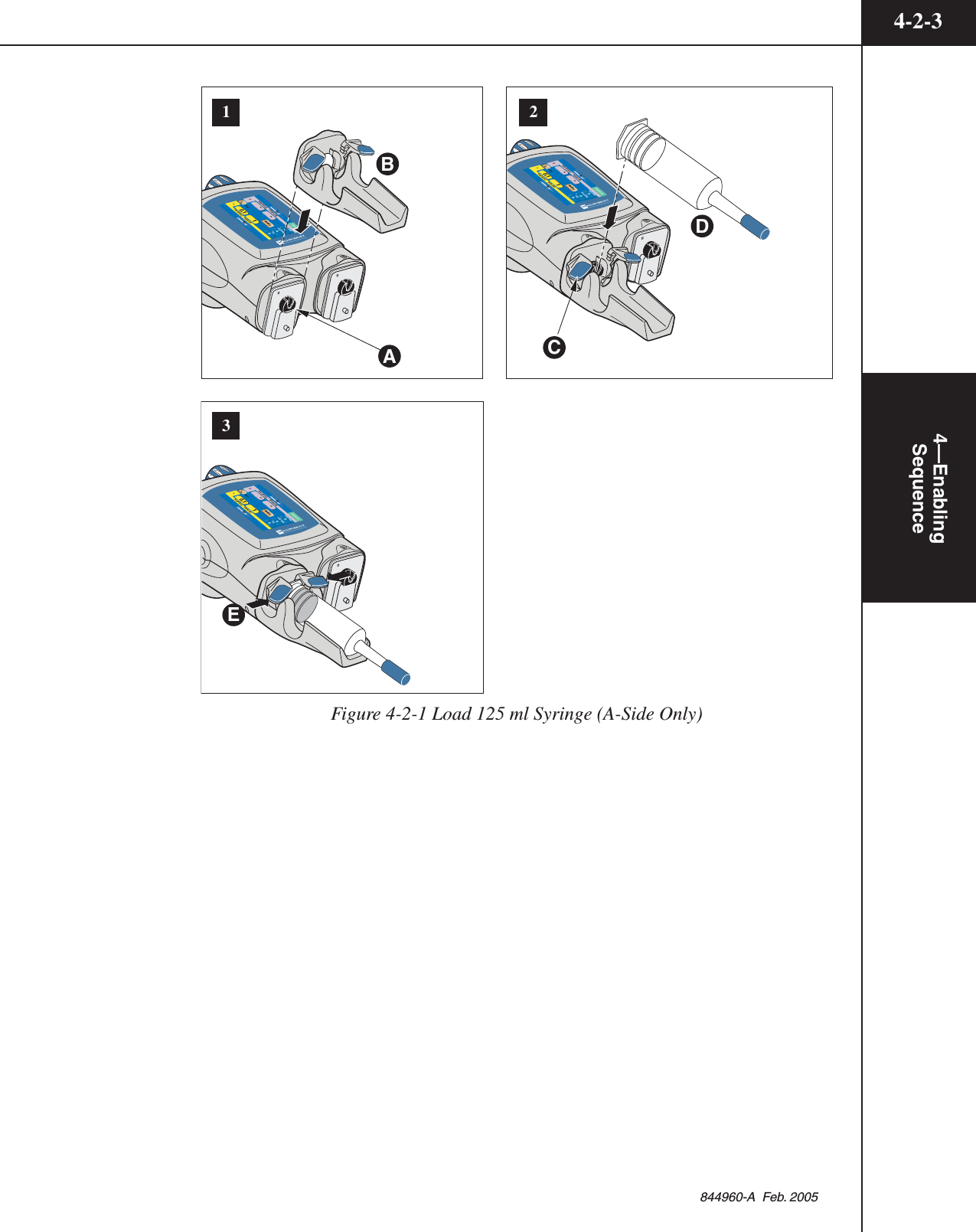
![4—EnablingSequence4-2-2844960-A Feb. 2005Load 125 ml Syringe (Contrast side Only)Refer to Figure 4-2-1.1. If the ram is not home, move to the fully retracted position A. Slide the 125ml cradle B onto the desired front plate mount of the powerhead (A-side isshown in Figure 4-2-1). Press the [Continue] key on the powerhead display toallow the ram to move forward to lock the faceplate in place and home theram.2. Inspect syringe and its contents for irregularities prior to loading. Open the125 ml syringe clamps C. Install the 125 ml syringe into the cradle D.3. Securely close syringe clamps E.4. Proceed to Section 4.1.4 Attach Tubing to Syringe(s).](https://usermanual.wiki/Tyco-Healthcare-Mallkrodt/844003/User-Guide-698150-Page-96.png)
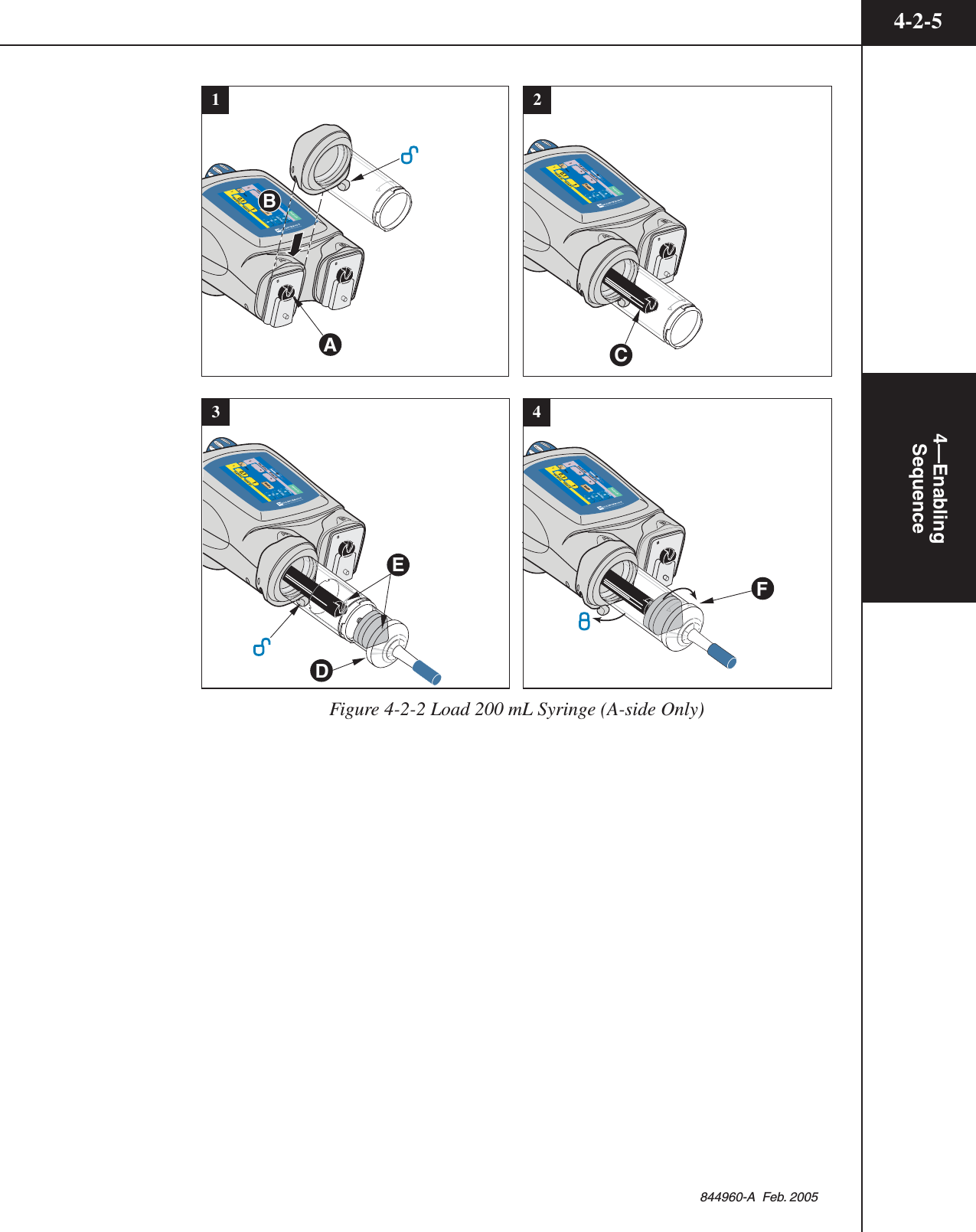
![4—EnablingSequence4-2-4844960-A Feb. 2005Load 200 ml Syringe (Contrast side Only)Refer to Figure 4-2-2.1. Move the desired ram to the fully retracted position A (A-side is shown inFigure 4-2-2). Rotate the pressure sleeve lever to the unlock position .Slide the 200 ml pressure sleeve onto the front plate mount of thepowerhead B. Press the [Continue] key on the powerhead display to allow theram to move forward to lock the faceplate in place and home the ram.2. Extend the ram fully C.3. Using aseptic technique, remove the 200 ml syringe from its sterile packagingby grasping the umbrella cap D. Inspect the syringe for irregularities prior toloading. Make sure the pressure sleeve lever is rotated to the unlockposition . Insert the 200 ml syringe into the pressure sleeve by matching theload arrow on the syringe to the load arrow on the pressure sleeve E.4. Lock the syringe into place by either turning the pressure sleeve lever to thelock position or by rotating the umbrella cap clockwise until the load arrowaligns as shown F. If the lever cannot be moved to the lock position, makesure the load arrow is aligned as shown E , then gently push down on theumbrella cap. The lever should now lock easily. Leave the ram/plunger in the"fully expelled" or extended position in preparation to fill with contrast.5. Proceed to section 4.3 Fill Syringe (200 mL Only).](https://usermanual.wiki/Tyco-Healthcare-Mallkrodt/844003/User-Guide-698150-Page-98.png)
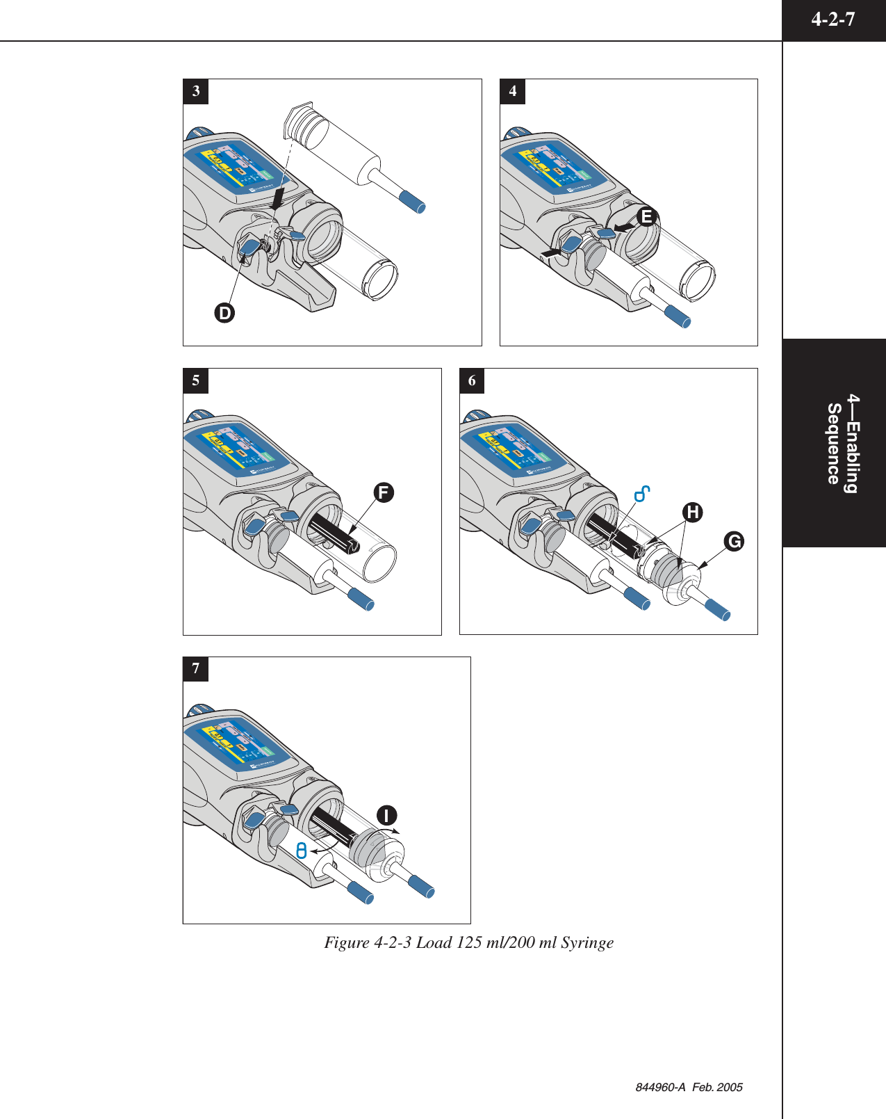
![4—EnablingSequence4-2-6844960-A Feb. 2005Load 125 ml/200 ml SyringeRefer to Figure 4-2-3.1. Move the A-side and B-side ram to the fully retracted position A. Slide the125 ml cradle onto the A-side front plate mount of the powerhead B. Pressthe [Continue] key on the powerhead display to allow the ram to move for-ward to lock the faceplate in place and home the ram.2. Rotate the pressure sleeve lever to the unlock position . Slide the 200 mlpressure sleeve onto the front plate mount of the powerhead C. Press the[Continue] key on the powerhead display to allow the ram to move forward tolock the faceplate in place and home the ram.3. Inspect 125 ml syringe and its contents for irregularities prior to loading.Open the tabs D and install the 125 ml syringe into the cradle4. Close tabs to secure the 125 ml syringe E.5. Extend the B-side ram fully F.6. Using aseptic technique, remove the 200 ml syringe from its sterile packagingby grasping the umbrella cap G. Inspect the syringe for irregularities prior toloading. Insert the 200 ml syringe into the 200 ml pressure sleeve by matchingthe load arrow H on the syringe to the load arrow on the pressure sleeve.7. Lock the syringe into place by either turning the pressure sleeve lever to the"lock" position or by rotating the umbrella cap clockwise until the loadarrow aligns as shown I. If the lever cannot be moved to the lock position,make sure the load arrow is aligned as shown H, then gently push down onthe umbrella cap. The lever should now lock easily. Leave the ram/plunger inthe "fully expelled" or extended position in preparation to fill with contrast.8. Proceed to section 4.3 Fill Syringe (200 ml Only).21-0.11--Inject DelayScan DelayName12Flow (ml/sec) Volume (ml) Flow (ml/sec) Volume (ml) PSI000AAEnableCheck for air5050-0.11--Inject DelayScan DelayName12Flow (ml/sec) Volume (ml) Flow (ml/sec) Volume (ml) PSI000AAEnableCheck for air5050ABC](https://usermanual.wiki/Tyco-Healthcare-Mallkrodt/844003/User-Guide-698150-Page-100.png)
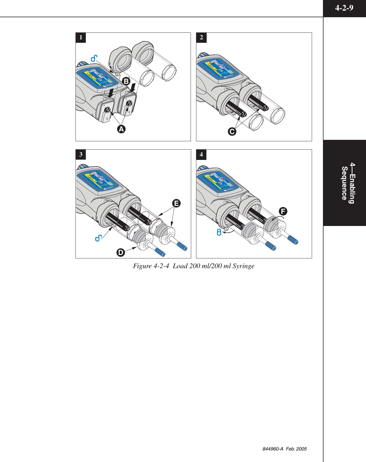
![4—EnablingSequence4-2-8844960-A Feb. 2005Load 200 ml/200 ml SyringeRefer to Figure 4-2-4.1. Move the A-side and B-side ram to the fully retracted position A. Rotate thepressure sleeve lever to the unlock position . Slide one of the 200 ml pres-sure sleeves onto the front plate mount of the powerhead B. Press the[Continue] key on the powerhead display to allow the ram to move forward tolock the faceplate in place and home the ram. Slide the other 200 ml pressuresleeves onto the front plate mount of the powerhead B. Press the [Continue]key on the powerhead display to allow the ram to move forward to lock thefaceplate in place and home the ram.2. Extend both rams fully C.3. Using aseptic technique, remove the 200 ml syringes from their sterile packag-ing by grasping their umbrella caps D. Inspect the syringes for irregularitiesprior to loading. Insert a 200 ml syringe into each pressure sleeve by matchingthe load arrow on the syringe to the load arrow on the pressure sleeve E.4. Lock the syringes into place by either turning the pressure sleeve levers to the"lock" position or by rotating the umbrella caps clockwise until the loadarrows align as shown. If the lever cannot be moved to the lock position, makesure the load arrows are aligned as shown, then gently push down on theumbrella cap. The lever should now lock easily. Leave the ram/plungers in the"fully expelled" or extended position in preparation to fill with contrast.5. Proceed to section 4.3 Fill Syringe (200 ml Only).](https://usermanual.wiki/Tyco-Healthcare-Mallkrodt/844003/User-Guide-698150-Page-102.png)

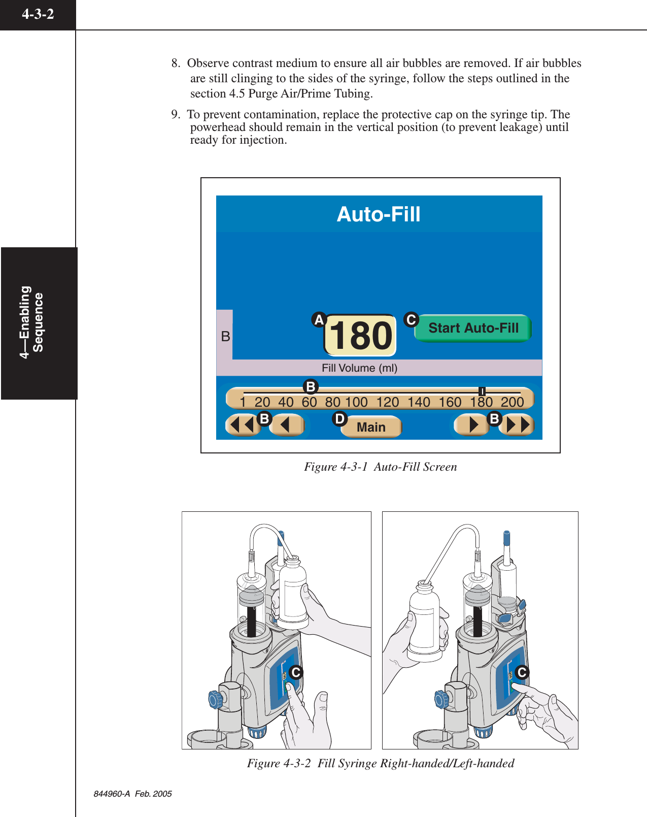
![4-3-14—EnablingSequence844960-A Feb. 20054.3 FILL SYRINGE (200 ML ONLY)4.3.1 AUTO-FILL TECHNIQUERefer to Figure 4-3-1 and 4-3-2.NOTE: This feature is only available if turned ON in the Setup screen.The Auto-Fill feature has been designed to automatically fill the syringe whileminimizing the introduction of air. To use the Auto-Fill feature:1. Place the ram(s) in the “home” position (i.e. fully expelled), then load a 200 mlsyringe into the pressure sleeve(s). If the powerhead is not in the verticalposition, the following message will appear: Rotate the Powerhead to thevertical position to activate Auto-Fill sequence.2. Rotate the powerhead to the vertical position. The screen shown inFigure 4-3-1 is displayed. NOTE: If the powerhead is utilizing a 200 mlsyringe on both the A-side and the B-side, the Auto-Fill sequence will first fillthe last installed syringe, then allow for filling the remaining empty syringe.3. Set the desired Fill Volume (ml) by pressing the [Fill Volume] key A for eitherthe A-side or the B-side (B-side is shown in Figure 4-3-1), then change thevalue via the slide bar keys B.4. Remove the protective cap from the syringe tip and store in a safe place forreuse in step 9.5. Using aseptic technique, slide the end of the shorter section of the fill tube overthe syringe tip. DO NOT TOUCH THE TIP. Place the end of the longersection of the fill tube into the container of contrast media. To keep aeration toa minimum, verify that this end of the tube is in the media and is NOT draw-ing air.6. Press and release the respective [Start Auto-Fill] key C. The injector willautomatically retract the ram 25 ml at 4 ml/s, purge 25 ml at 10 ml/s, thenretract to the Fill Volume at 15 ml/s. NOTE: Pressing the [Stop] key on thescreen will disable the Auto-Fill feature.7. Carefully remove the fill tube from the syringe tip by twisting while pullingoff. NOTE: In order to prevent the contrast medium from spilling onto thesyringe and pressure sleeve, make sure the curved portion of the fill tube iseither completely empty or contains enough contrast medium so that the levelin the longer end is slightly lower than the tip of the syringe. This will causethe fluid in the tube to return to the container.](https://usermanual.wiki/Tyco-Healthcare-Mallkrodt/844003/User-Guide-698150-Page-105.png)
![4-3-34—EnablingSequence844960-A Feb. 20054.3.2 MANUAL FILL TECHNIQUEUpon loading a 200 ml syringe, the screen shown in Figure 4-3-1 is displayed (ifAuto-Fill feature is turned ON in the Setup screen) to allow for automatic fillingof the syringe. The Auto-Fill feature has been designed to automatically fill thesyringe while minimizing the introduction of air. However, to manually fill thesyringe:1. Disable the Auto-Fill feature by pressing the [Main] key ( D in Figure 4-3-1) todisplay the Main screen.2. Rotate the powerhead to the vertical position.3. Remove the protective cap from the syringe tip and store in a safe place for reusein step 9.4. Slide the end of the shorter section of the fill tube over the syringe tip. DO NOTTOUCH THE TIP. Place the end of the longer section of the fill tube into thecontainer of contrast media. To keep aeration to a minimum, verify that this endof the tube is in the media and is NOT drawing air.5. Press the respective syringe key to display the fill/expel arrows. Retract theplunger to draw the desired volume of contrast medium into the syringe.NOTE: A retract flow of 10 ml/s or less is optimum to minimize the introduc-tion of air.6. Move the plunger in the “expel” direction, to expel all air from the syringe.7. Carefully remove the fill tube from the syringe tip by twisting while pullingoff. NOTE: In order to prevent the contrast medium from spilling downaround the syringe and pressure sleeve, make sure the curved portion of thefill tube is either completely empty or contains enough contrast medium sothat the level in the longer end is slightly lower than the tip of the syringe.This will cause the fluid in the tube to return to the container.8. Observe contrast medium to ensure all air bubbles are removed. If air bubblesare still clinging to the sides of the syringe, follow the steps outlined in thesection 4.5 Purge Air/Prime Tubing.9. To prevent contamination, replace the protective cap on the syringe tip. Thepowerhead should remain in the vertical position (to prevent leakage) untilready for injection.](https://usermanual.wiki/Tyco-Healthcare-Mallkrodt/844003/User-Guide-698150-Page-107.png)


![4-7-14—EnablingSequence844960-A Feb. 20054.7 POWERHEAD IN VERTICAL POSITIONWith all air removed and the tubing primed, the powerhead should remain in thevertical position A (to prevent leakage) until ready to inject. The [Enable] keywill activate once the powerhead is rotated 30° below horizontal B.Inject DelayScan DelayName1Flow (ml/sec) Volume (ml) Peak PSI0000.1 10.1-10.1AAEnable2Flow (ml/sec) Volume (ml) 120120Inject DelayLiver ExaminationABFlow (ml/sec) Volume (ml)Flow (ml/sec) Volume (ml)73AA1584.04.0 83Scan DelayPeak PSI1580020EnableBA](https://usermanual.wiki/Tyco-Healthcare-Mallkrodt/844003/User-Guide-698150-Page-115.png)


![5—Delivering anInjection5-4-1844960-A Feb. 20055.4 ENABLE INJECTORRefer to Figure 5-4-1.1. The operator is responsible for ensuring that all air has been completelyevacuated from the syringe and tubing prior to delivering the injection.Prior to enabling an injection, review all parameters thoroughly to ensure thatthey are correct and appropriate for the procedure. Also, ensure that the con-trast fluid is installed on the correct side of the powerhead.2. Follow the Enabling Sequence stated in Chapter 4 to properly load and fillsyringes, purge air and prime the tubing.3. Rotate the Powerhead at least 30° below horizontal. This safety precautionreduces the possibility of an air emboli. Any small remaining air bubbles willtend to float away from the tip and will not be injected into the patient.4. Press the [Enable] key located on either the powerhead or console screen. A[Start] key A will appear in the upper right-hand corner of both the consolescreen and the powerhead screen. The [Enable] key will change to a [Disable]key B. The indicator lights on the powerhead will illuminate to signify theunit is now enabled for delivery of an injection.PH1:PH2:PH3:PH4:PH5:PH6:To t a lTimeInject DelayScan DelayPeak PSI00:316254.0 100 04.0 25AB-A:125B:200120 ml10000Start180 mlProtocol NamePhase Side Flow Volume Duration Phase Delay ml/sec ml sec sec OptiBolus Timing BolusDisableDripBDAInject DelayProtocol Name21Flow (ml/sec) Volume (ml)Flow (ml/sec) Volume (ml)254.04.0 100Scan DelayPeak PSI00100120180AADisableStartPatencyDripABConsole Enabled ScreenPowerhead Enabled ScreenCDFigure 5-4-1 Enabled Screen](https://usermanual.wiki/Tyco-Healthcare-Mallkrodt/844003/User-Guide-698150-Page-123.png)

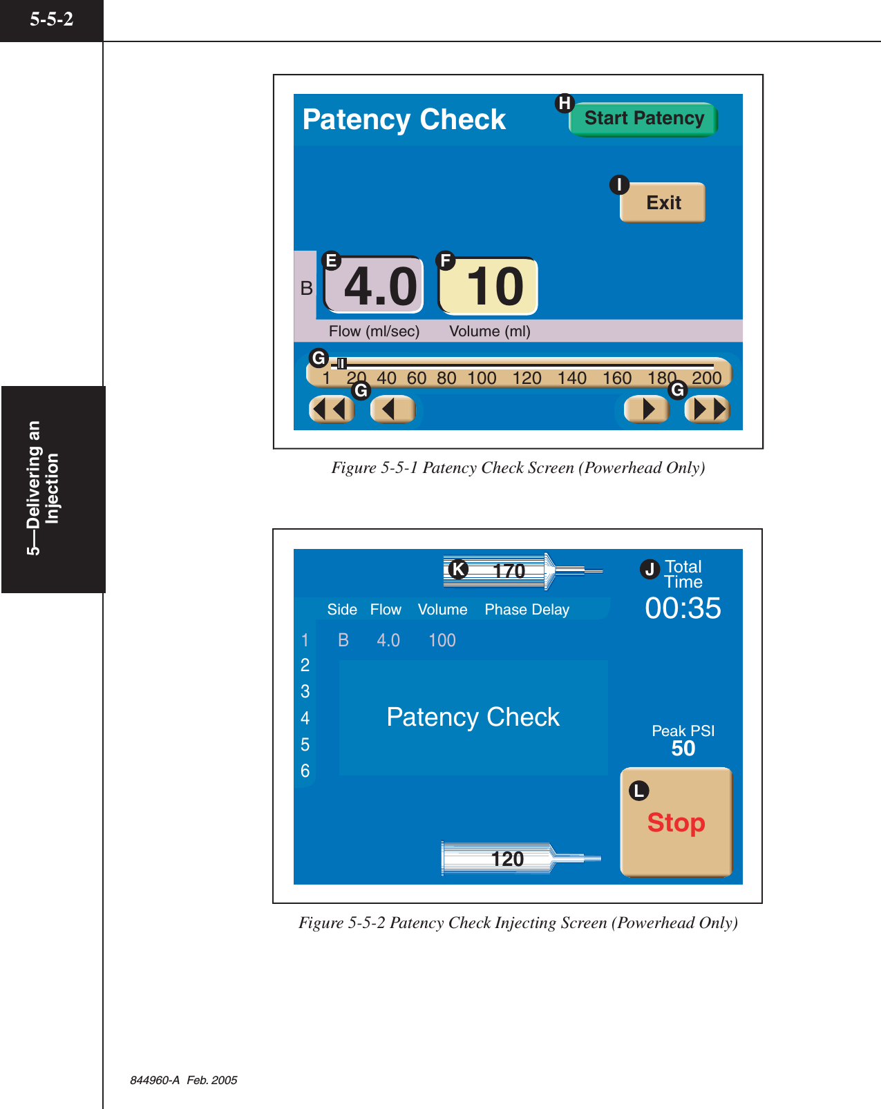
![5—Delivering anInjection5-5-1844960-A Feb. 20055.5 CHECK PATENCY OF I.V. SITEWARNING!Extravasation can be minimized through the following precautions: • When choosing an I.V. site, use the largest vein possible. • Use lowest flow rate practical to achieve enhancement. • Use largest gauge teflon type catheter possible. • Insure good backflow from catheter. • Continue to monitor from remote location. • Instruct patient to notify operator of any abnormal pain, pressure or swelling.NOTE: The injector does not have the capability to prevent or detect anextravasation. Patency Check is only available when turned On in the Setupscreen.Two different techniques exist to check the patency of the I.V. site. Once a proto-col is enabled, the [Patency] key is available on the powerhead display to inject asmall volume of saline at the same flow rate as the enabled protocol. Also, themanual knob is available to manually check patency. Instructions for both tech-niques follow:Check Patency Using the [Patency] keyRefer to Figure 5-5-1 and 5-5-2.1. Press the [Patency] key (C on Figure 5-4-1) located on the powerhead'senabled screen. The screen as shown in Figure 5-5-1 appears.2. Adjust Patency Check flow E and Patency Check volume F as desired usingthe slide bar G. Patency Check Volume can only be set to an amount that willnot compromise the enabled protocol.3. Press the [Start Patency] key H to start the injection and the screen as shownin Figure 5-5-3 will display. Monitor the site and instruct patient to notifyoperator of any abnormal pain, pressure or swelling.4. Total Time J increments and syringe volume K decrements while injecting.The [Stop] key L is available to immediately stop the Patency Check injec-tion at any time.5. Once the Patency Check injection is delivered, the Enabled screen is displayedand the injector is ready to deliver the protocol or deliver another PatencyCheck.](https://usermanual.wiki/Tyco-Healthcare-Mallkrodt/844003/User-Guide-698150-Page-125.png)

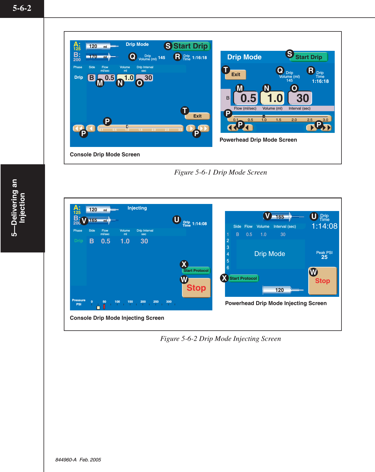
![5—Delivering anInjection5-6-1844960-A Feb. 20055.6 DELIVERING A DRIP MODE INJECTIONRefer to Figure 5-6-1 and 5-6-2.CAUTION!REVIEW PARAMETERSThe enabled protocol can be delivered via the Drip Mode injecting screen bypressing the [Start Protocol] key X. If this feature will be utilized, prior to press-ing the [Drip] key on the enabled main screen, review all protocol parametersthoroughly to ensure that they are correct and appropriate for the procedure. Also,ensure that contrast fluid is installed on the correct side of the powerhead.1. Press the [Drip] key (D on Figure 5-4-1) located on the powerhead's enabledscreen. The screen as shown in Figure 5-6-1 appears.2. Adjust Drip flow M, Drip volume N and Drip interval O as desired using theslide bar P. Drip volume can only be set to an amount that will not compro-mise the enabled protocol. Drip (injectable) Volume Q displays the amount ofsaline available for the Drip Mode injection. Drip Time R displays theamount of time the Drip Mode injection will require.3. Press the [Start Drip] key S to start the injection and the screen as shown inFigure 5-6-2 will display. The [Exit] key T is available to exit the Drip Modeand return to the Enabled protocol screen.4. While injecting, Drip Time U and syringe volume V decrement. The[Stop] key W is available to stop the injection at any time. Pressing the[Start Protocol] key X immediately starts delivery of the main protocol.5. Once the Drip injection is delivered, the following message is displayed:WARNING!The Drip Mode Injection is complete.Start the Enabled Protocol.Press Close to return to the Start screen.Press the [Close] key and the Enabled protocol screen (Start screen) is dis-played. The injector is now ready to deliver the main protocol. Adjustments tothe protocol parameters can be made prior to starting delivery of the mainprotocol.](https://usermanual.wiki/Tyco-Healthcare-Mallkrodt/844003/User-Guide-698150-Page-129.png)
![5—Delivering anInjection5-7-1844960-A Feb. 20055.7 DELIVERING THE MAIN PROTOCOL5.7.1 DANGERS, WARNINGS AND CAUTIONSDANGER!OPERATOR DUE DILIGENCE REQUIRED!Delivering an injection to a patient requires due diligence on the part of theoperator. Air entrapped in the syringe and tubing can cause patient injury ordeath. Always verify that both the syringe and tubing have been properly clearedof air just prior to starting the injection! The OptiVantage Injection System doesnot have the capability to check for air in the syringe and tubing. The operator isresponsible for removing all air from the system.CAUTION!REVIEW PARAMETERSPrior to delivering an injection, review all parameters thoroughly to ensure thatthey are correct and appropriate for the procedure. Also, ensure that the contrastfluid is installed on the correct side of the powerhead.5.7.2 STARTING DELIVERY OF THE MAIN PROTOCOLRefer to Figure 5-7-1.The protocol can be delivered by pressing the [Start] key (A on Figure 5-4-1)either on the powerhead or the console or by pressing the remote handswitch.Once the injection is initiated, the Injecting screen, shown in Figure 5-7-1, isdisplayed, Total Time increments and syringe volume decrements. Note that thePeak PSI (pressure limit) parameter is indicated by the red line a. The currentinjecting pressure is indicated by the white bar b.](https://usermanual.wiki/Tyco-Healthcare-Mallkrodt/844003/User-Guide-698150-Page-131.png)
![5—Delivering anInjection5-7-2844960-A Feb. 2005PH1:PH2:PH3:PH4:PH5:PH6:To t a lTimeInject DelayScan Delay00:024.04.025 0610025AB-A:125B:200115 ml00 25 mlProtocol NameInjectingPhase Side Flow Volume Duration Phase Delay ml/sec ml sec sec Powerhead Injecting ScreenConsole Injecting Screen123456A 4.0 100 0B 4.0 25 Side Flow Volume Phase DelayStopTo t a lTime00:02Inject Delay0Scan Delay0Peak PSI50PressurePSI 0 50 100 150 200 250 300StopVabV25115Figure 5-7-1 Injecting Screen5.7.3 PAUSING AN INJECTIONRefer to Figure 5-7-1 and Figure 5-7-2.An injection may be immediately paused by pressing the [Stop] key ( V on Figure5-7-1) on the console display or the powerhead display and also by depressingonce on the handswitch. When the injector is paused, the screen shown in Figure5-7-2 is displayed and the status lights on the console and powerhead will flashtheir respective color every 1/2 second.While the injection is paused, the values for the flow rate, volume and phase delaycan be changed on either the console screen or the powerhead screen. However,phases cannot be added or deleted when the injector is paused.](https://usermanual.wiki/Tyco-Healthcare-Mallkrodt/844003/User-Guide-698150-Page-132.png)
![5—Delivering anInjection5-7-3844960-A Feb. 2005PH1:PH2:PH3:PH4:PH5:PH6:To t a lTimeInject DelayScan DelayPeak PSI00:106234.0 95 04.0 25AB-A:125B:200110 ml5000StartInjection PausedInjection Paused 45 mlProtocol NamePhase Side Flow Volume Duration Phase Delay ml/sec ml sec sec DisableXWConsole Paused ScreenPowerhead Paused ScreenTo t a lTime00:10Inject Delay0Scan Delay0Peak PSI50Start0A4.04.0952523 6 Side Flow Volume Duration Phase Delay ml/sec ml sec sec123B-DisableWXFigure 5-7-2 Injection Paused Screens5.7.4 RESTARTING A PAUSED INJECTIONRefer to Figure 5-7-2.The injection can be restarted by pressing the [Start] key W on the console or thepowerhead paused screens. The achieved values displayed on the Results screenafter completion of the restarted injection represent the total volume deliveredfrom the start of the injection and the average flow rate achieved since the restart.5.7.5 TERMINATING AN INJECTIONRefer to Figure 5-7-1 and Figure 5-7-2.Press the [Stop] key (V on Figure 5-7-1) then the [Disable] key (X onFigure 5-7-2) on the powerhead screen or console screen to terminate an injection.](https://usermanual.wiki/Tyco-Healthcare-Mallkrodt/844003/User-Guide-698150-Page-133.png)

![5—Delivering anInjection5-8-1844960-A Feb. 20055.8 DISPLAYING RESULTS SCREENRefer to Figure 5-8-1.Average flow rate, delivered volume and achieved pressure are displayed on boththe console and the powerhead Results screen at the completion of the injection.Press the [Main] key A to display the Main screen.Powerhead Results ScreenConsole Results ScreenPhase Side Flow Volume Duration ml/sec ml sec Phase DelaysecPH1:PH2:PH4:PH5:PH6:TotalTimeInject DelayScan Delay03:26624 04.0 974.0 25AB-PressurePSI0 50 100 150 200 250 300A:125B:125 15 ml00Injection Completed onFEB 3 2005 9:50Protocol NameResultsMain 20 ml Side Flow Volume Phase Delay12345604.0 974.0 25AB- 15 ResultsInjection CompleteFeb 3 2005 9:5020MainA ATo t a lTime03:26Inject Delay0Scan Delay0Peak PSI50Figure 5-8-1 Results Screens](https://usermanual.wiki/Tyco-Healthcare-Mallkrodt/844003/User-Guide-698150-Page-135.png)


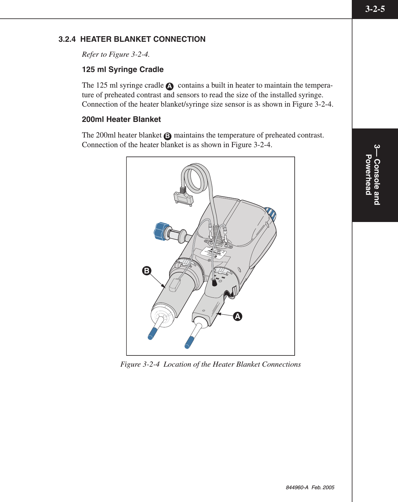
![6—System Messages6-1-3844960-A Feb. 2005Changing Fluid ConfigurationMessage: The syringe fluid configuration has changed. This will prevent access tothe stored protocols. Do you want to continue with these settings?Occurs when: This message occurs when the operator updates the settings in theSetup screen changing the fluid configuration (i.e. A-side:contrast, B-side: salinechanged to A-side:saline, B-side:contrast).Operator action: This message is for informational purposes only in order toadvise the operator that changing the fluid configurations will prevent access tostored protocols. Press the [Yes] key to continue with these settings. Press the[No] key to leave the fluid configuration unchanged.Heater BlanketPowerhead Message: Heater Blanket on this side of the injector has becomedisconnected or has failed. Check connection or call service. To continue withoutheater blanket, close window.Console Message: The heater blanket on the A-side of the injector has becomedisconnected or has failed. Check connection or call service. To continue withoutheater blanket, close window.Console Message: The heater blanket on the B-side of the injector has becomedisconnected or has failed. Check connection or call service. To continue withoutheater blanket, close window.Occurs when: One of the 200 ml heater blanket connectors is unplugged or mal-functioning.Operator action: Plug the heater blanket in or to use the injector without the heaterblanket, press the [Close] key on the screen and continue. Contact your ServiceDepartment for corrective action regarding this message.](https://usermanual.wiki/Tyco-Healthcare-Mallkrodt/844003/User-Guide-698150-Page-141.png)
![6—System Messages6-1-5844960-A Feb. 2005OptiBolus Key is not InstalledMessage: OptiBolus Key is not installed. Insert OptiBolus Key and press Close tocontinue.Occurs when: This message appears when the operator attempts to recall anOptiBolus protocol when the OptiBolus Key has been removed from the injector.Operator action: To recall an OptiBolus protocol, the OptiBolus key must beinstalled at the rear of the power control. Install the OptiBolus Key, press the[Close] key on the screen and continue.Patency Check in ProgressMessage: Patency Check in progress. Please wait...Occurs when: This message appears on the console screen when the powerhead isdelivering a Patency Check injection.Operator action: None.Programmed to Deliver Contrast from both Side A and Side BMessage: Attention, the current protocol is programmed to deliver contrast onSide A and Side B. Press Close to continue.Occurs when: The injector is set up for Contrast (A-side)/Contrast (B-side)delivery.Operator action: This message is for informational purposes only in order toadvise the operator to use caution when delivering more than 125 ml of contrastinto a patient. Delivering more than 125 ml of contrast into one patient is notadvised.](https://usermanual.wiki/Tyco-Healthcare-Mallkrodt/844003/User-Guide-698150-Page-143.png)
![6—System Messages6-1-6844960-A Feb. 2005Protocol Modification in Progress at ConsoleMessage: Protocol modification in progress at console. Please wait...Occurs when: This message appears on the Powerhead display to inform theoperator that Protocol modification is taking place at the Console display.Operator action: The Powerhead display will refresh upon pressing the [Main] keyon the Console.Protocol Name Already ExistsMessage: Protocol name already exists. Please change or cancel.Occurs when: The operator enters an existing protocol name on the keyboardwhen trying to store a new protocol.Operator action: Enter a new protocol name or press the [Cancel] key.Protocol Name Not ValidMessage: Protocol name not valid. Please change or cancel.Occurs when: The operator enters a protocol name that is blank or begins with aspace.Operator action: Enter a new, valid protocol name or press the [Cancel] key.Setup to Deliver Contrast from A-side and B-sideMessage: Settings on the Setup Screen will allow contrast to be injected from bothsides of the injector. Contrast injections in excess of a single full syringe arepossible. Do you want to continue with these settings? Yes/NoOccurs when: This message occurs when the operator updates the settings in theSetup screen for Syringe Fluid A: Contrast (A-side)/Syringe Fluid B: Contrast (B-side) delivery.Operator action: This message is for informational purposes only in order toadvise the operator to use caution when injecting more than one syringe of con-trast into a patient. Injecting more than one syringe of contrast into one patient isnot advised. Press the [Yes] key to continue with Contrast (A-side)/Contrast (B-side) delivery. Press the [No] key to change the setting for either Syringe Fluid Aor Syringe Fluid B.](https://usermanual.wiki/Tyco-Healthcare-Mallkrodt/844003/User-Guide-698150-Page-144.png)
![6—System Messages6-1-7844960-A Feb. 2005Unreadable Data on Powerhead or Console DisplayMessage: NO MESSAGE ASSOCIATED WITH THIS CONDITION.Occurs when: Any single user display contains unreadable data.Operator action: The injector can be used, with caution, if any single user displaycontains unreadable data. Cycle power to reset injector. If this condition persists,contact your Service Department for corrective action. If this issue persists,contact your Service Department for corrective action.Volume Key Flashing a Magenta ColorMessage: NO MESSAGE ASSOCIATED WITH THIS CONDITION.Occurs when 1: The volume key(s) on the main screen will flash a magenta colorto indicate that its value(s) is greater than the volume contained in its respectivesyringe.Operator action: Lower the value of the applicable volume key(s) or fill thesyringe(s) with an adequate amount of fluid.Occurs when 2: The volume key on the Drip Mode screen or Patency Checkscreen will flash a magenta color to indicate that delivering this amount willcompromise the volume available for the main protocol. Note that if the Volumekey is flashing a Magenta Color, the [Start Drip] key or the [Start Patency] keywill not appear.Operator action: Lower the value of the volume key or fill the syringe with morefluid.](https://usermanual.wiki/Tyco-Healthcare-Mallkrodt/844003/User-Guide-698150-Page-145.png)
![6—System Messages6-1-8844960-A Feb. 20056.1.3 FACEPLATE MESSAGESNew Faceplate InstalledMessage: A new Faceplate Adapter has been detected. Make sure the new Adapteris properly installed. Press Continue and the ram will automatically move forwardto lock the faceplate.Occurs when: A new faceplate is installed on the injector.Operator action: Press the [Continue} key to allow the injector to automaticallymove the ram in order to lock the faceplate into place.6.1.4 AUTO-FILL MESSAGESRotate the Powerhead to Activate Auto-FillMessage: Rotate the Powerhead to the vertical position to activate Auto-Fillsequence.Occurs when: This message occurs when a 200 ml syringe is installed [with theram in the “home’ (fully expelled) position] but the powerhead is not oriented inthe vertical position. The Auto-Fill screen is automatically displayed when 1) theram is in the “home” position 2) a 200 ml syringe is installed and then 3) thepowerhead is rotated to the vertical position.Operator action: This message is for informational purposes only in order toadvise the operator to rotate the powerhead to the vertical position in order toaccess the Auto-Fill feature.6.1.5 SCANNER CONNECTIVITYScanner Interface Connection not AvailableMessage: The Scanner Interface connection is not available. To continue withoutthe interface, close window.Occurs when: When the OEM Interface on the Setup screen in set to On, but theOEM interface is not communicating with the injector properly, this messageoccurs.Operator action: To continue without the OEM interace, press the [Close] key.Contact your Service Department for corrective action regarding this message.](https://usermanual.wiki/Tyco-Healthcare-Mallkrodt/844003/User-Guide-698150-Page-146.png)
![6—System Messages6-1-9844960-A Feb. 20056.1.6 ENABLE PROCESS MESSAGESEnable sequence not completedConsole Message: The Enable sequence has not been completed at the Power-head.Powerhead Messages: for 125 ml syringe/faceplate for 200 ml syringe/faceplateThe Enable sequence is not complete. The Enable sequence is not complete.Install a new syringe. Install a new syringe.Tilt Powerhead up. Tilt Powerhead up.Purge syringe. Fill syringe.Tilt powerhead down. Purge syringe.Tilt powerhead down.Occurs when: As an additional precaution against the injection of an air embo-lism, the injector’s software checks for a “Purge sequence” (125 ml syringe) and a“Fill/Purge sequence” (200 ml syringe) before allowing the injector to be enabled.If the Purge Sequence or Fill/Purge Sequence has not occurred and the [Enable]key is pressed, the console message will appear and the appropriate powerheadmessage [missed step(s)] will appear. If correct steps have been taken on either theA-side or the B-side, the message “This side ready.” will appear.Operator action: Follow the step indicated on the powerhead to allow the injectorto be enabled. Note that it is the operator’s responsibility to ensure the syringeand tubing does not contain air.Hand switch is closed.Message: The hand switch is closed. Please check hand switch and press Close tocontinue.Occurs when: As a safety precaution to prevent unintentional injections, theinjector cannot be enabled if its hand switch is closed. If the hand switch is closedand the injector’s enable key is pressed, this message appears.Operator action: Check the appropriate switch to ensure that it is open. Oncechecked, press the [Close] key and continue the enable process. If you are unableto open the switch (as indicated by the return of this message), unplug the handswitch and continue. Contact your Service Department for corrective actionregarding the hand switch.](https://usermanual.wiki/Tyco-Healthcare-Mallkrodt/844003/User-Guide-698150-Page-147.png)
![6—System Messages6-1-10844960-A Feb. 2005Insufficient volumeMessage: Insufficient volume to run this injection.Occurs when: The [Enable] key is pressed when a volume key is flashing a ma-genta color. The volume key(s) on the main screen flash a magenta color toindicate that its value(s) is greater than the volume contained in its respectivesyringe.Operator action: Lower the value of the applicable volume key(s) or fill the sy-ringe with more fluid. Note that it is the operator’s responsibility to ensure thesyringe and tubing does not contain air.6.1.7 INJECTION STOPPED MESSAGESDrip ExpiredMessage: WARNING! The Drip Mode injection is complete. Start the EnabledProtocol. Press Close to return to the Start screen.Occurs when: This message appears when the Drip Mode injection is complete.Operator action: Press the [Close] key to return to the Start screen to allow fordelivery of the main protocol.Injector StalledMessage: Injector Disabled! Injector stalled. Check fluid path for obstructions.Press Close to continue.Occurs when: This message appears if the injector has started an injection butcannot move the ram.Operator action: Press the [Close] key and check the fluid path for any obstruc-tions and remove them. Restart the Enable process.](https://usermanual.wiki/Tyco-Healthcare-Mallkrodt/844003/User-Guide-698150-Page-148.png)
![6—System Messages6-1-11844960-A Feb. 2005Pressure LimitingMessage: Injection is pressure limiting! Do you want to continue or stop?Occurs when: This message appears when the injector is injecting under maxi-mum pressure limit conditions and cannot achieve the set flow rate.Operator action: Press the [Continue] key to perform the injection under maxi-mum pressure limit conditions. Press the [Stop] key to review the Flow Rateparameter to ensure it is not set too high for the procedure and also review thePressure Limit parameter to ensure it is not set too low. Check the delivery systemfor closed stopcocks or kinked tubing. Under normal circumstances, the injectionpressure should not reach the pressure limit. Reaching the pressure limit defeatsthe purpose of a flow rate injector.Syringe Latch OpenMessage: The injection has stopped. A syringe latch is open. Press Close tocontinue.Occurs when: While the injector is enabled or injecting, the injector softwarechecks to ensure the 125 ml syringe clamps and/or the 200 ml syringe levers arein the loaded (closed) position. If either are opened, the injector will immediatelydisable and display this message.Operator action: Close the syringe clamps and/or levers. Press the [Close] key andre-enable the injector.](https://usermanual.wiki/Tyco-Healthcare-Mallkrodt/844003/User-Guide-698150-Page-149.png)
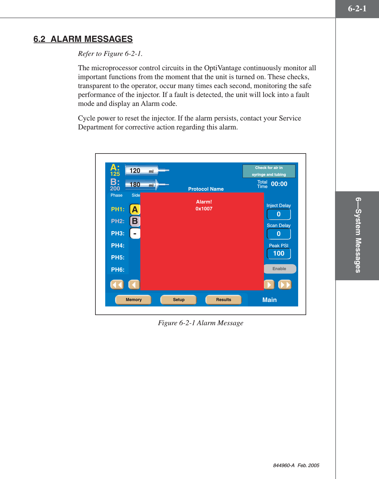


![I—IndexI-1-1844960-A Feb. 2005IndexAAccessories 1-7-1Alarm Messages 6-2-1Alarms Screen 3-1-24Attach Tubing to Syringe(s) 4-4-1Auto-Fill Feature 1-4-2Auto-Fill Technique (200 ml Only) 4-3-1CCare of Unit 7-1-1Cleaning 7-2-1Daily Inspection 7-1-1Catheters, Connectors and Tubing 1-6-2Check Patency of I.V. Site 5-5-1Check Patency Using the [Patency] key 5-5-1Check Patency Using the Manual Knob 5-5-3Cleaning 7-2-1125 ML Cradle Assembly 7-2-1200 ml Pressure Sleeve and Base 7-2-1Console and Powerhead 7-2-1Power supply 7-2-1Connect to Patient 5-3-1Console 3-1-2Console Display Modes of Operation 3-1-3Console Drip Mode Screen 3-1-10Console Main Screen 3-1-5Console Power Button 3-1-2Consumables 1-6-1DDaily Inspection 7-1-1Delete a Protocol 3-1-16Delivering a Drip Mode Injection 5-6-1Delivering an Injection 5-1-1Dangers/Warnings/Cautions 5-1-1Delivering the Main Protocol 5-7-1Dangers, Warnings and Cautions 5-7-1Pausing an Injection 5-7-2Restarting a Paused Injection 5-7-3Starting Delivery of the Main Protocol 5-7-1Terminating an Injection 5-7-3Dimensions 1-5-1Displaying Results Screen 5-8-1, 5-9-1Drip Mode Feature 1-4-1EElectrical Leakage 1-5-2Electrically Isolated Syringe 1-4-2Enable Injector 5-4-1Enabled Console Main Screen 3-1-9Enabled Powerhead Main Screen 3-2-16Enabling Sequence 4-1-1Dangers, Warnings, and Cautions 4-1-2Environmental 1-5-2FFill Syringe (200 ml Only) 4-3-1Flow Rate 1-5-3HHeater Blanket Connection 3-2-5Homing the Rams 2-2-1IIndications for Use 1-1-2Inject Delay 1-5-3LLanguage 3-1-23Load 125 ml Syringe (A-side Only) 4-2-2Load 125 ml/200 ml Syringe 4-2-6Load 200 ml Syringe (A-side Only) 4-2-4Load 200 ml/200 ml Syringe 4-2-8Low Pressure Tubing 1-6-2MManual Fill Technique (200 ml Only) 4-3-3Manual Knobs 3-2-2Memory Screen 3-1-12Move a Protocol 3-1-15](https://usermanual.wiki/Tyco-Healthcare-Mallkrodt/844003/User-Guide-698150-Page-157.png)