UTC Fire and Security Americas HD915FFH Wireless Heat Detector User Manual
UTC Fire & Security Americas Corporation Wireless Heat Detector
UserManual.wiki
>
UTC Fire and Security Americas
>
HD915FFH User Manual
User Manual
Navigation menu
Upload a User Manual
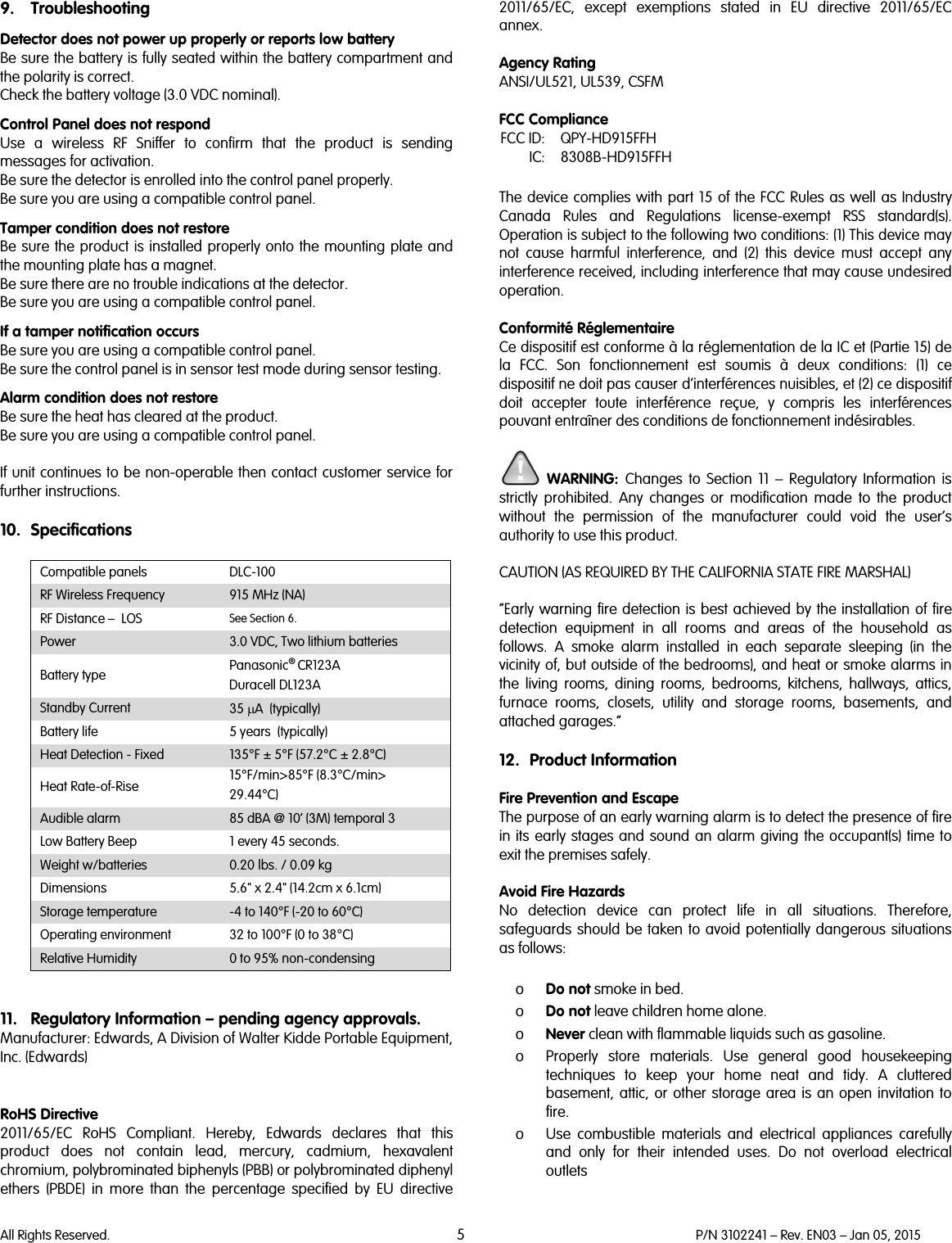
Namespaces
Wiki Guide
HTML
PDF
Info
Views
User Manual
Discussion / Help
Navigation