UTStarcom Korea Technologies UTS-600FSU Local loop desk phone User Manual CERTIFICATE OF COMPLIANCE
UTStarcom Korea Technologies Ltd. Local loop desk phone CERTIFICATE OF COMPLIANCE
UserManual.wiki
>
UTStarcom Korea Technologies
>
UTS-600FSU User Manual
>
Manaul
Contents
1.
Manaul
2.
Updated manual
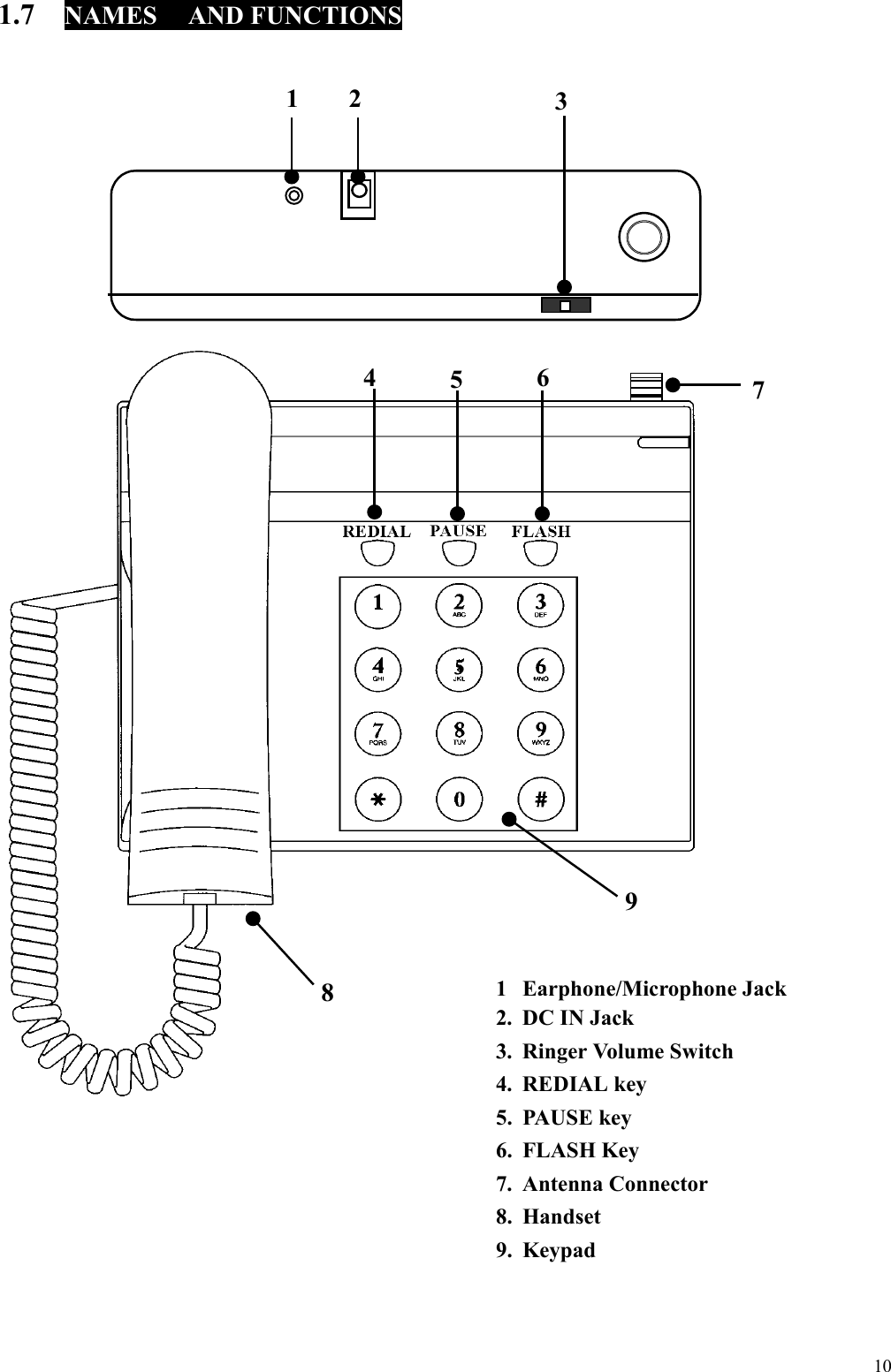
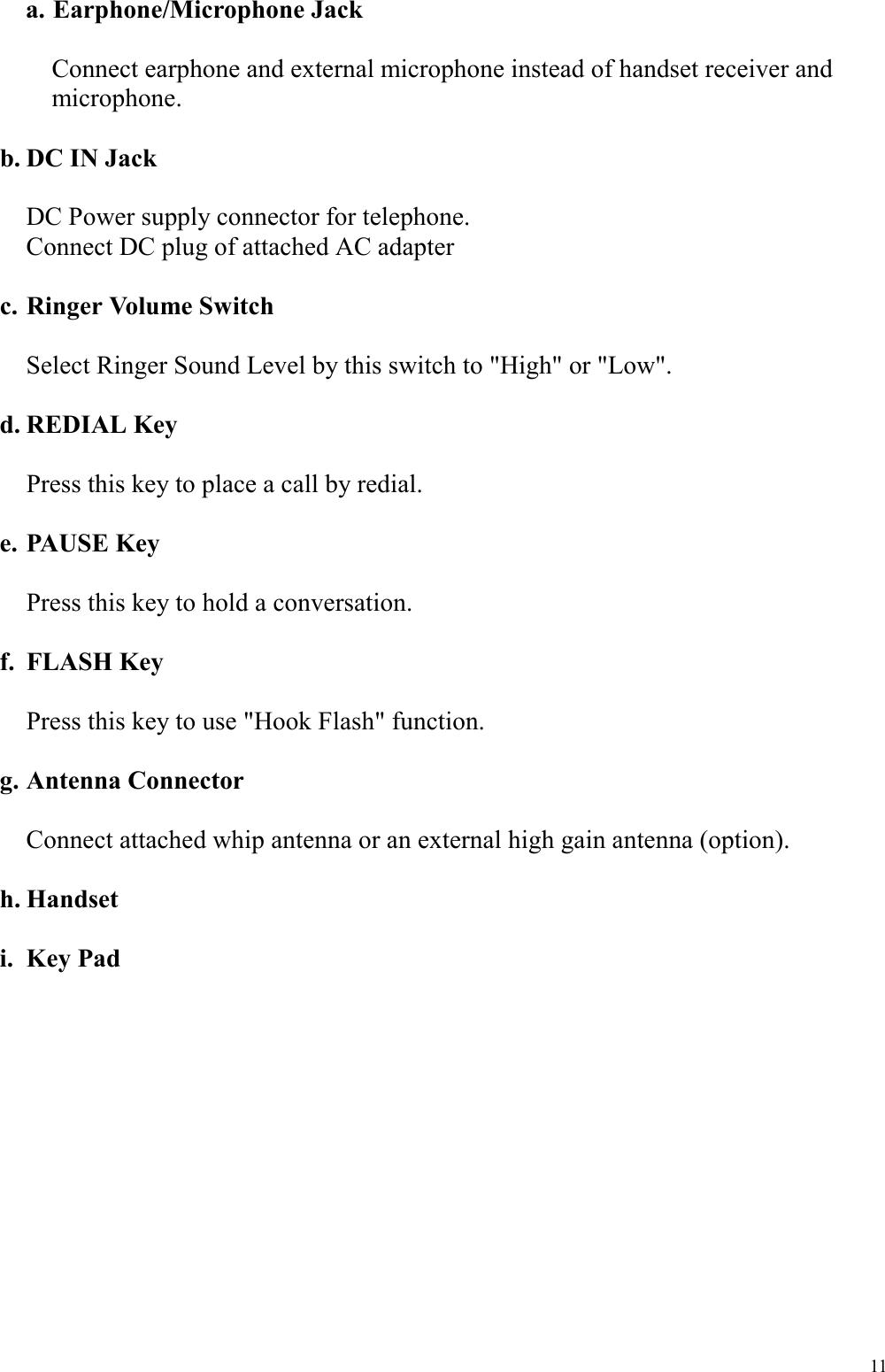
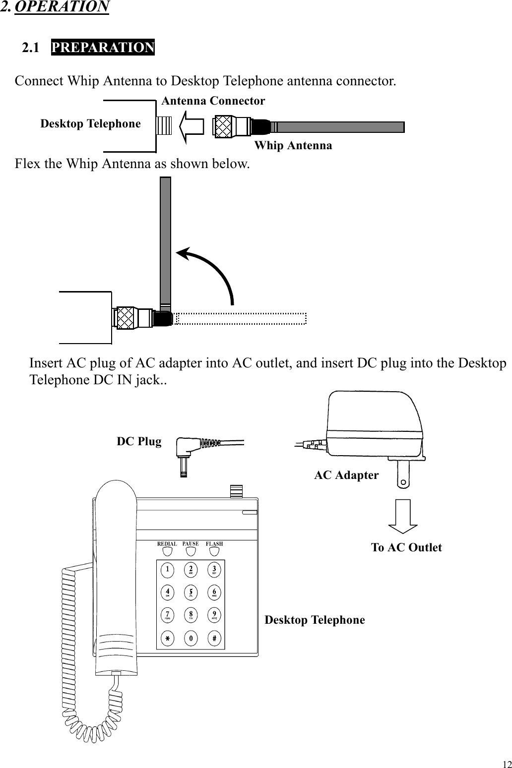
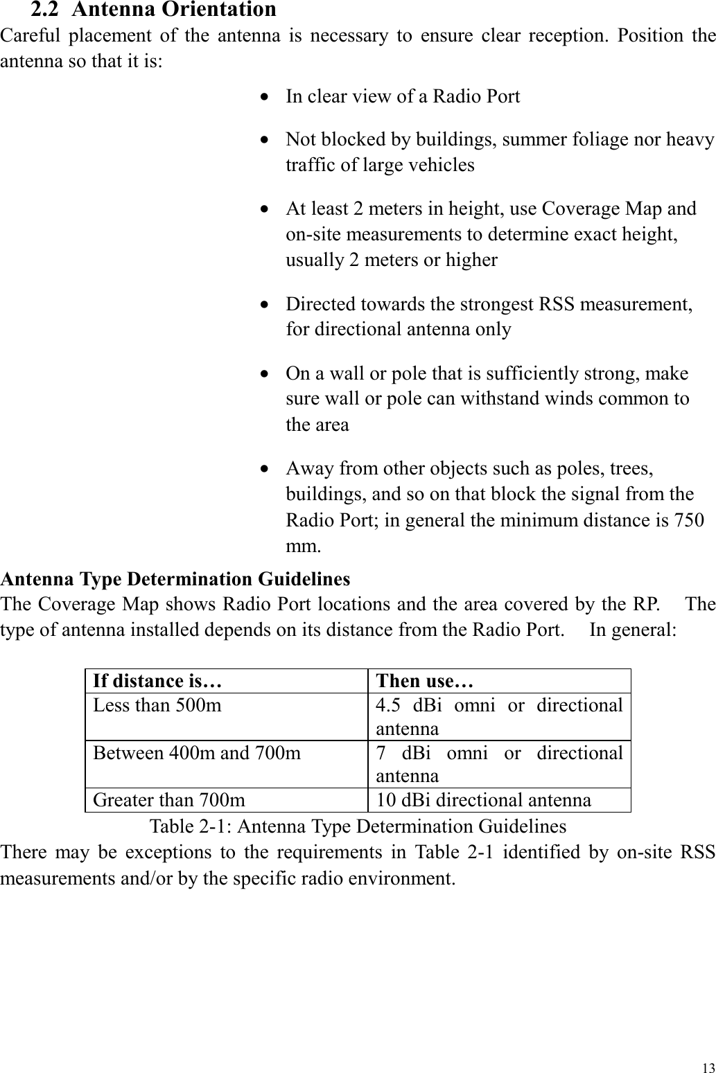
Manaul
Navigation menu
Upload a User Manual
Namespaces
Wiki Guide
HTML
PDF
Info
Views
User Manual
Discussion / Help
Navigation