UTStarcom MSG2000 Multi-Service Gateway User Manual
UTStarcom Inc. Multi-Service Gateway Users Manual
UserManual.wiki
>
UTStarcom
>
MSG2000 User Manual
Users Manual
Navigation menu
Upload a User Manual
Namespaces
Wiki Guide
HTML
PDF
Info
Views
User Manual
Discussion / Help
Navigation
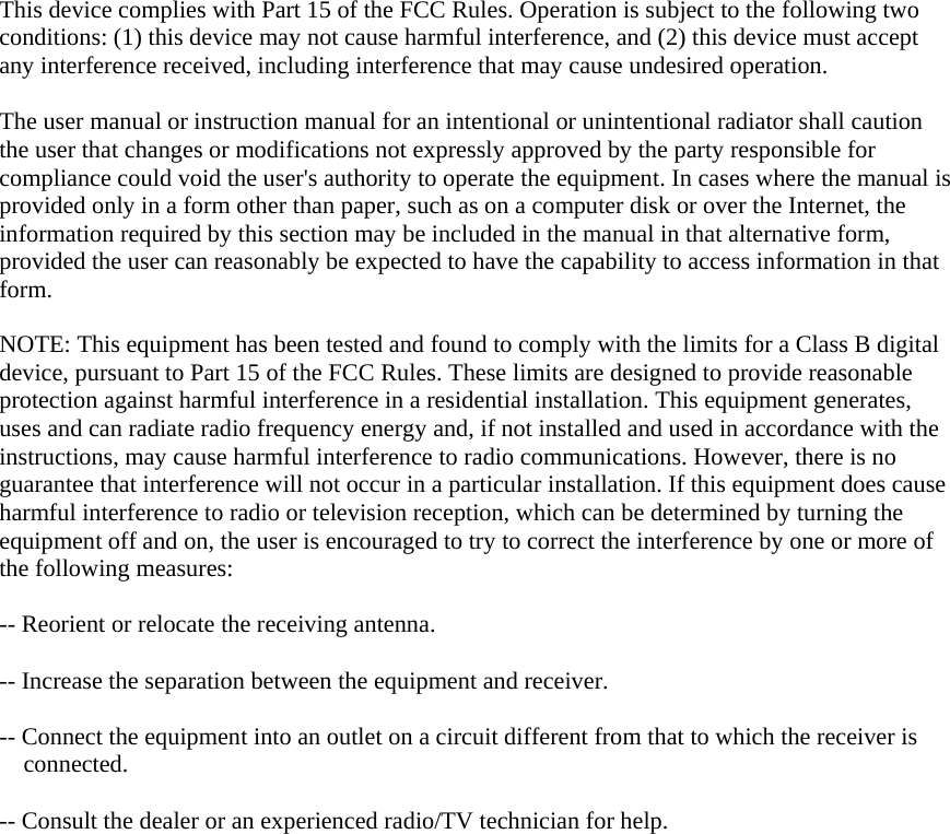
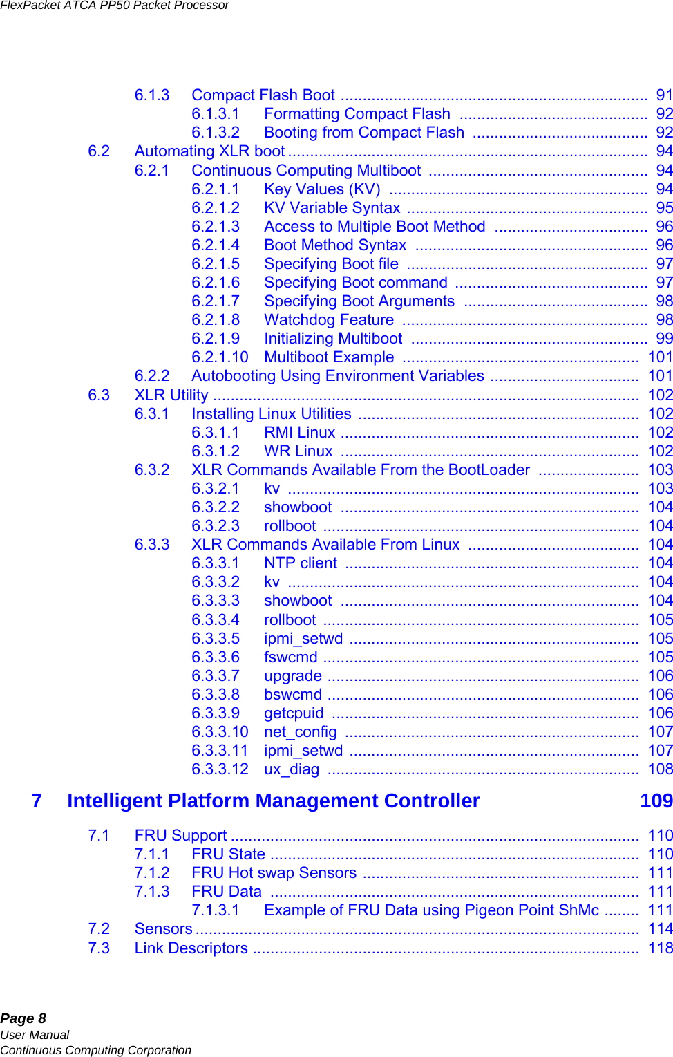
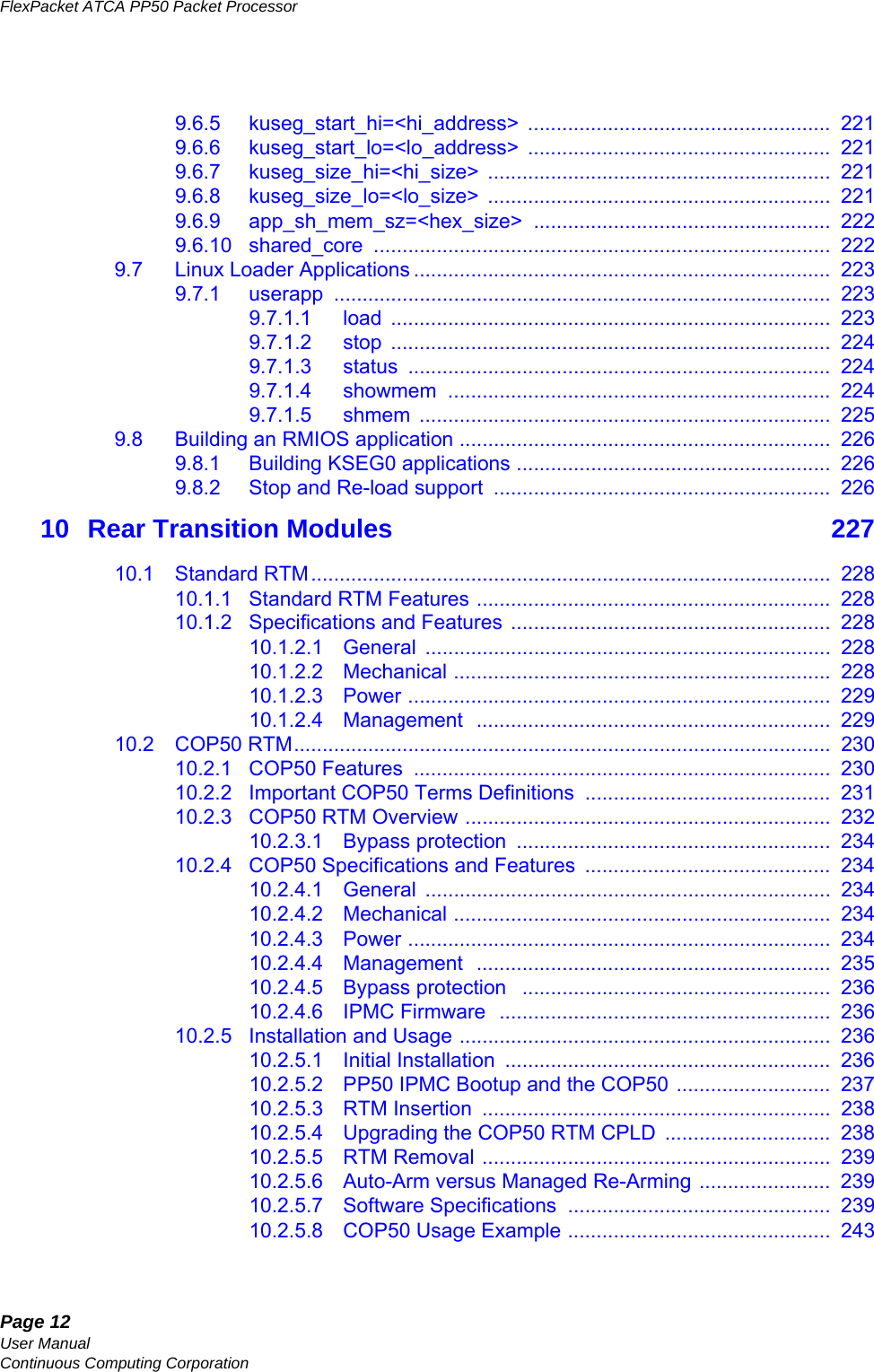
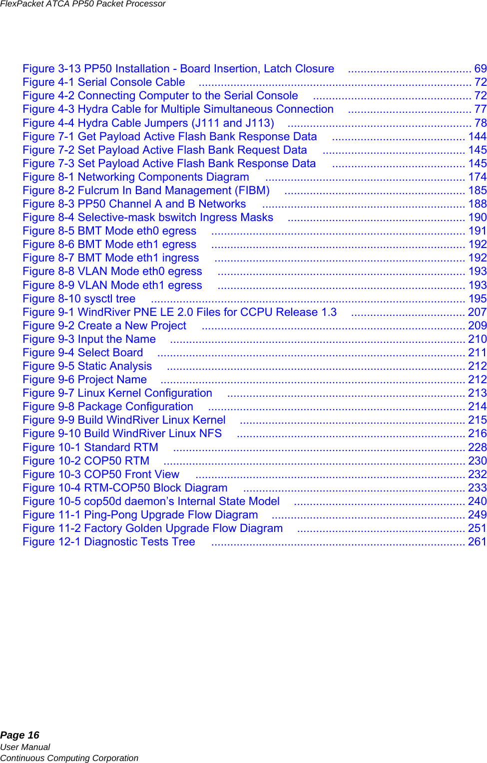
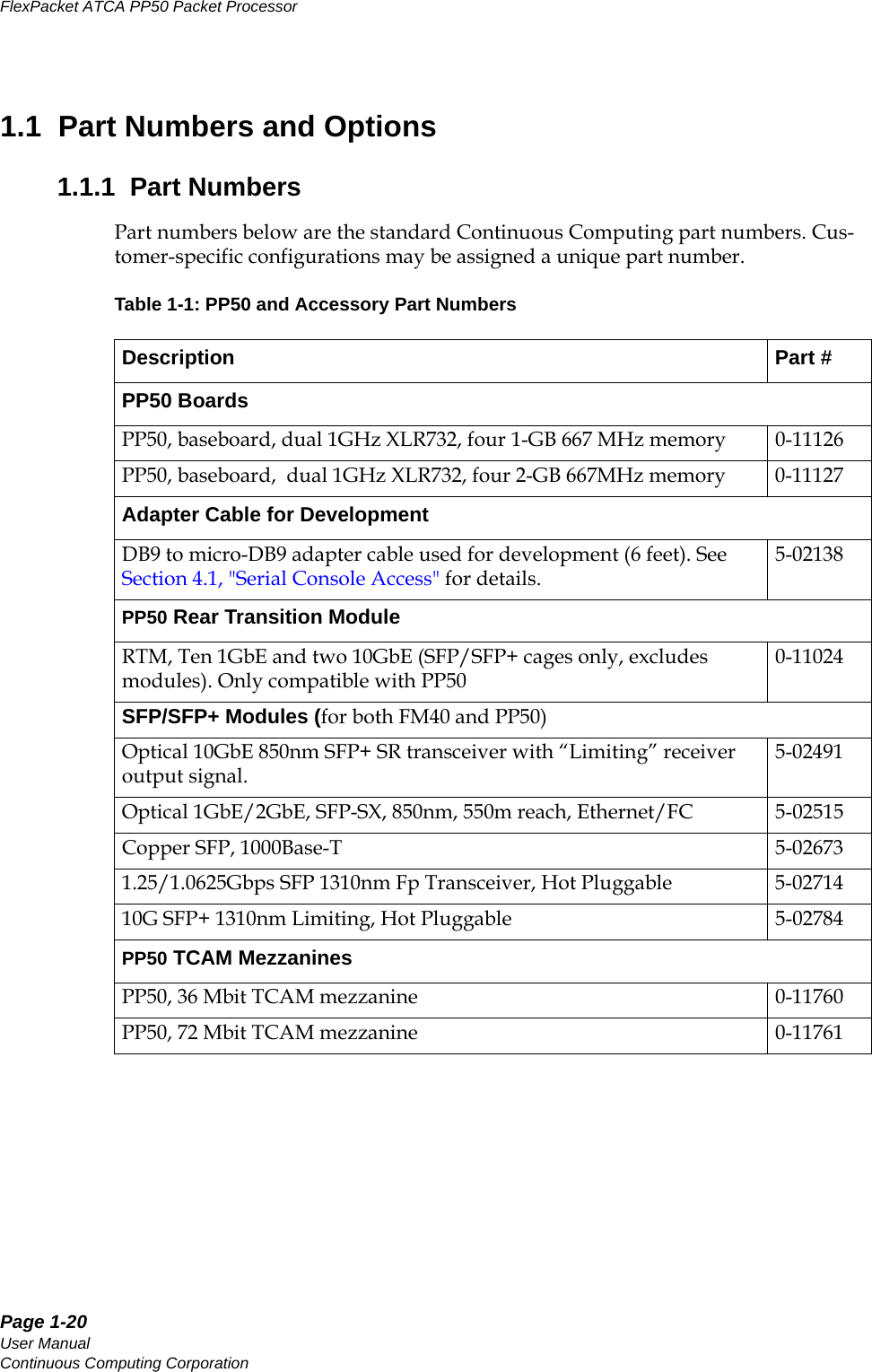
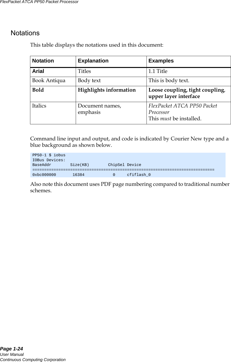

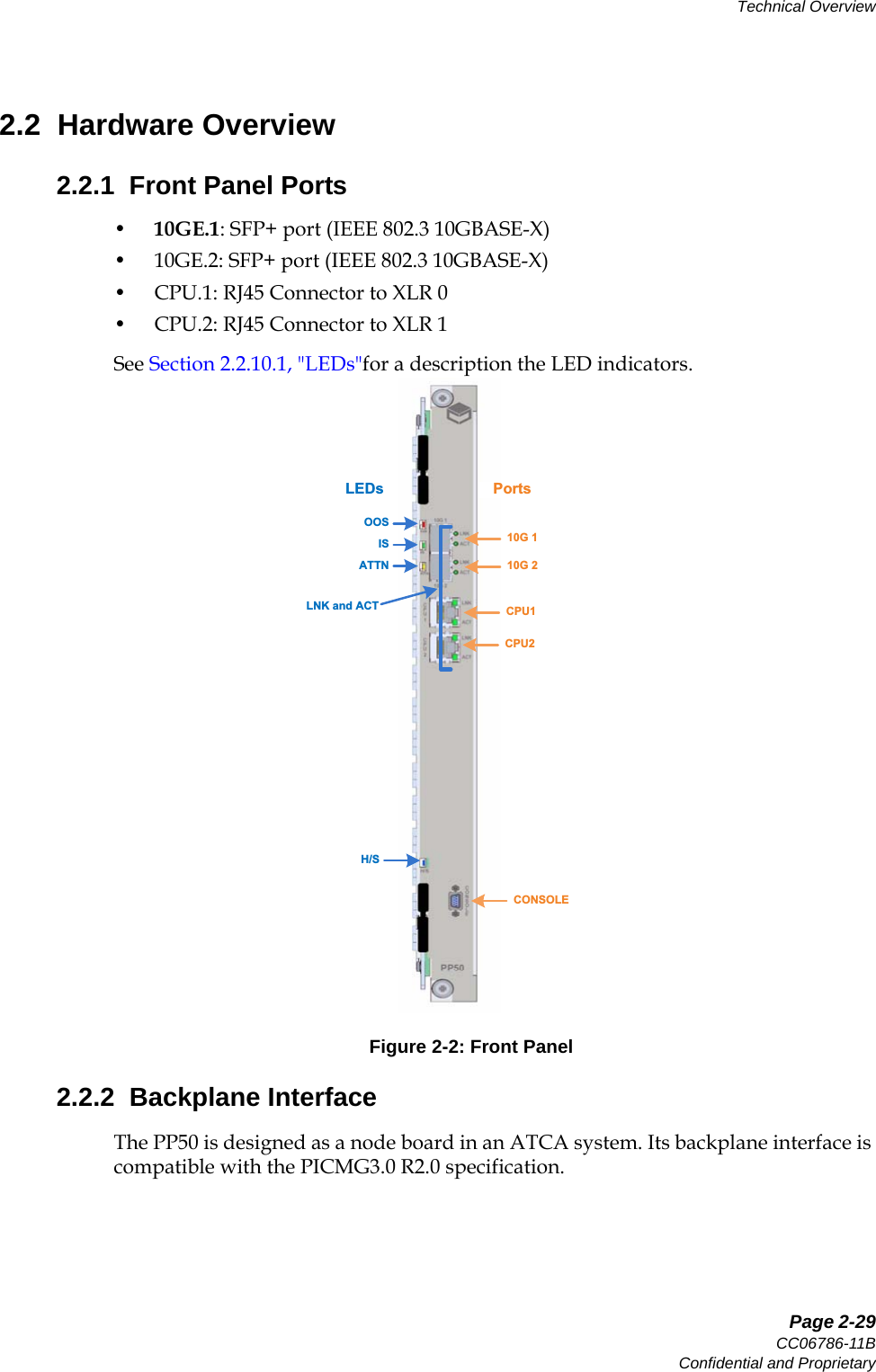
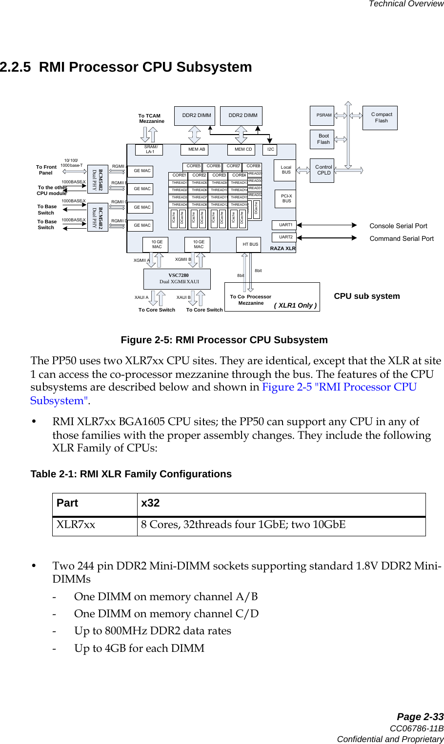
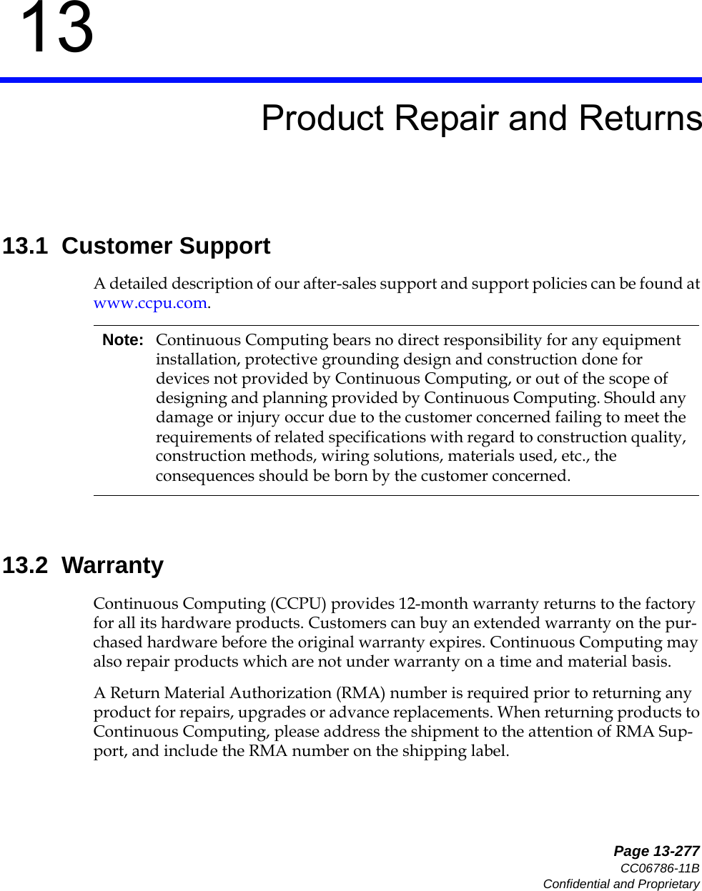
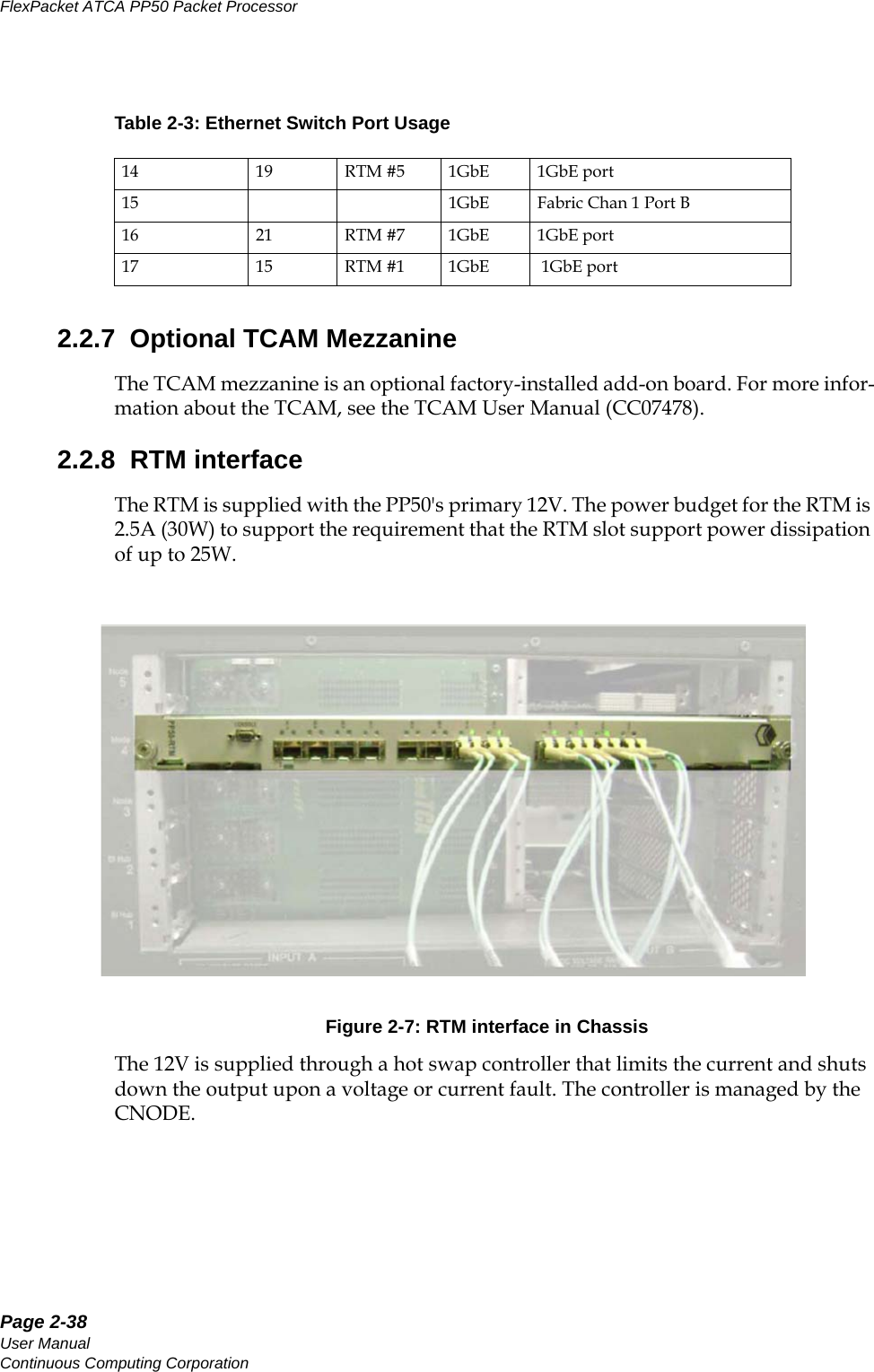
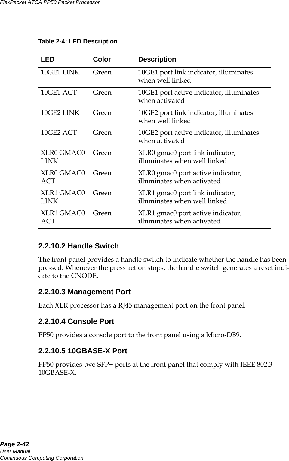
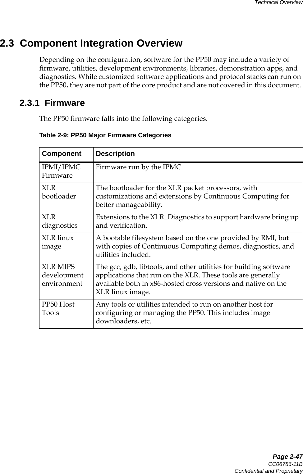
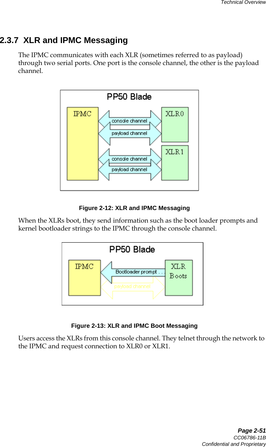
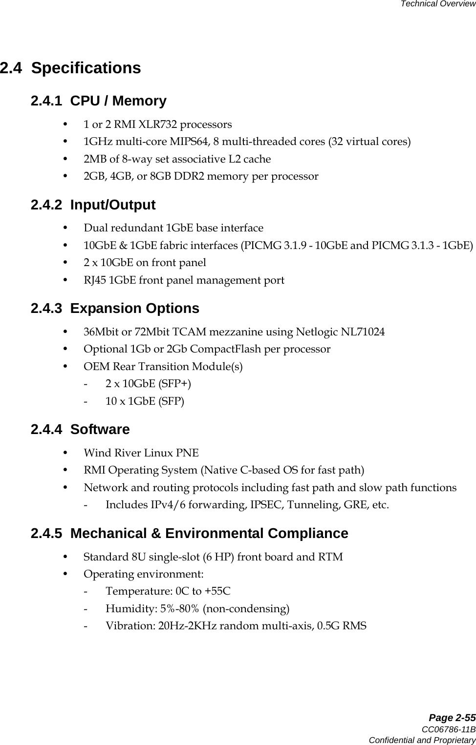
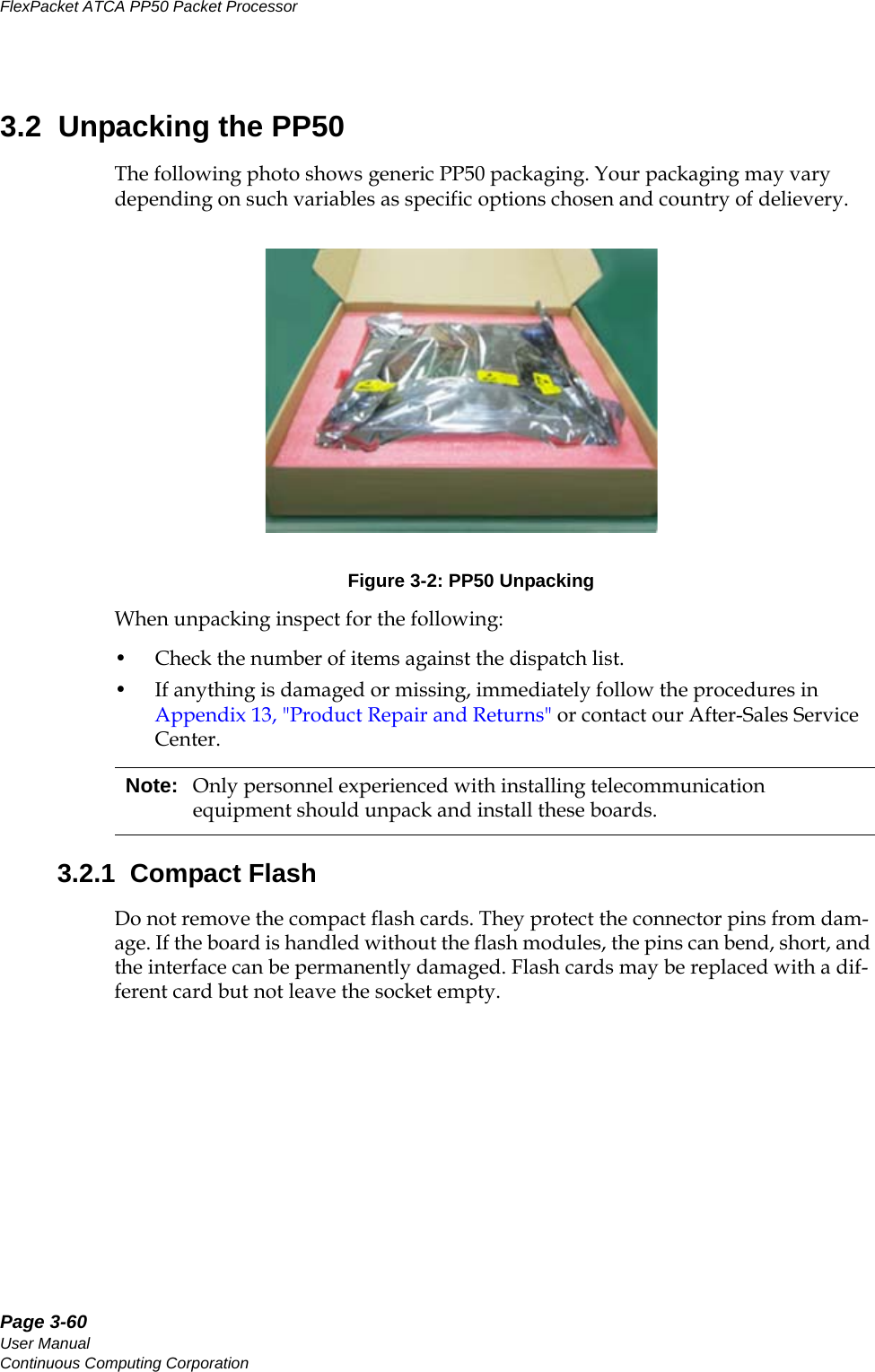
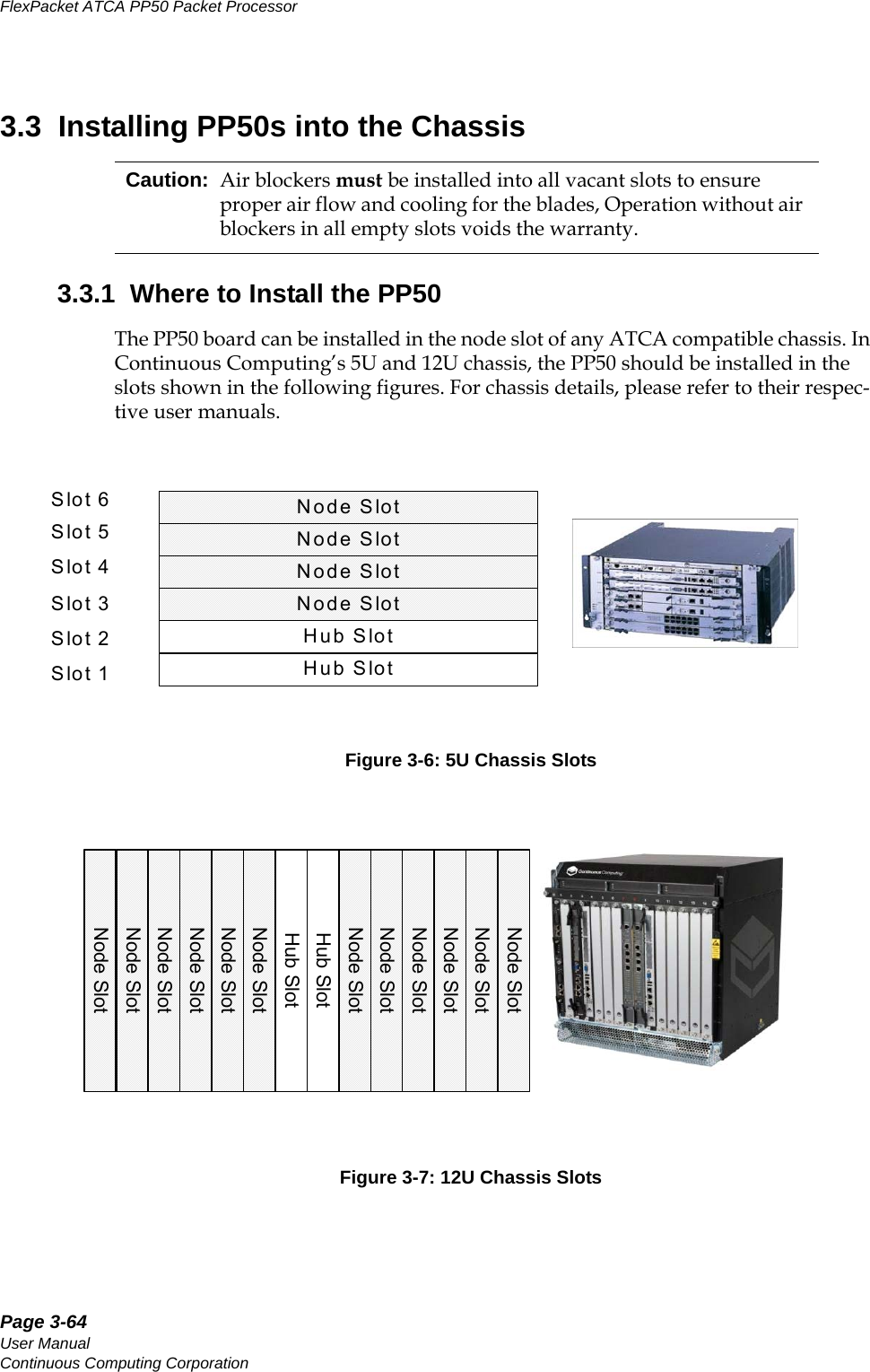
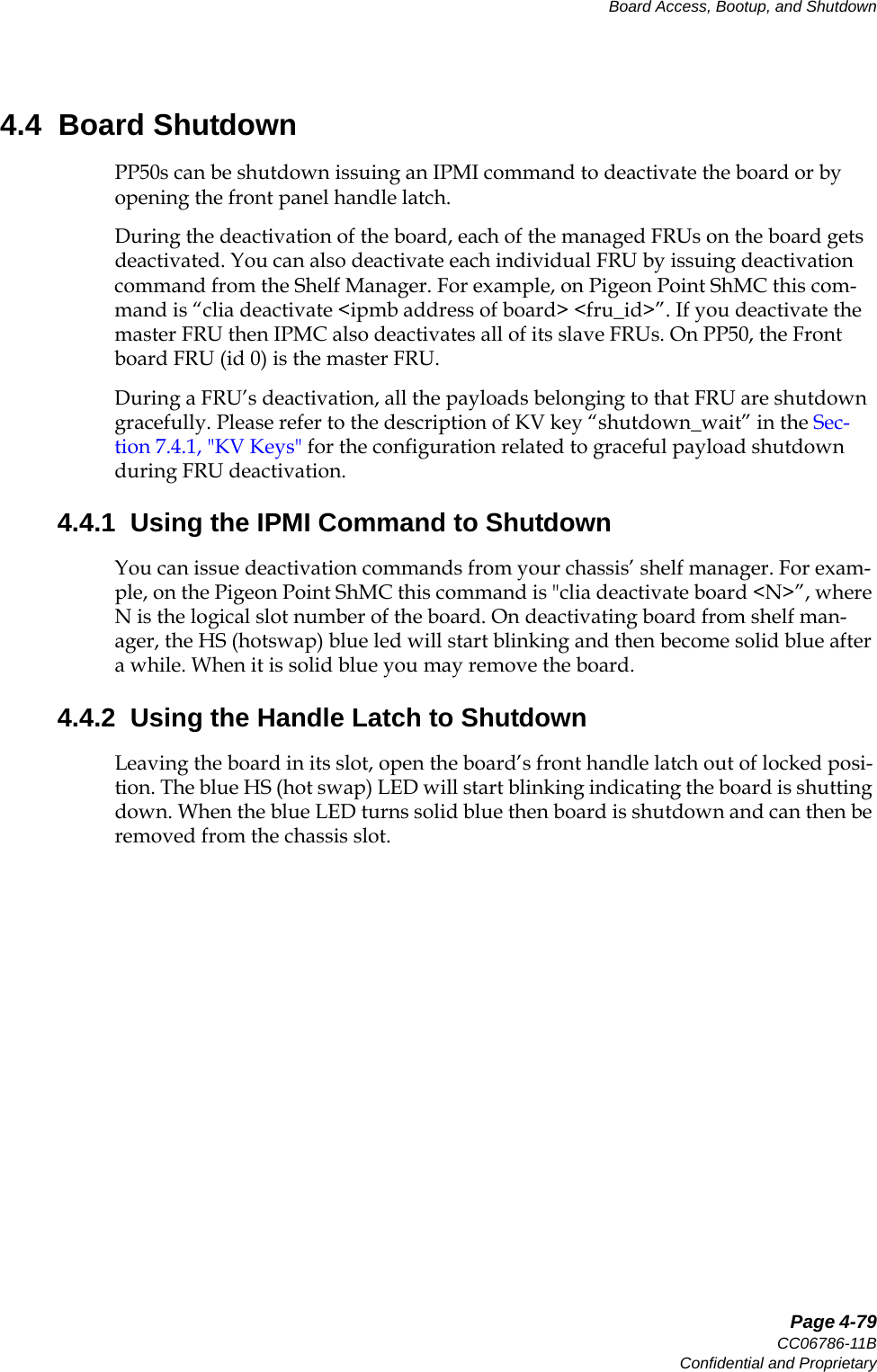
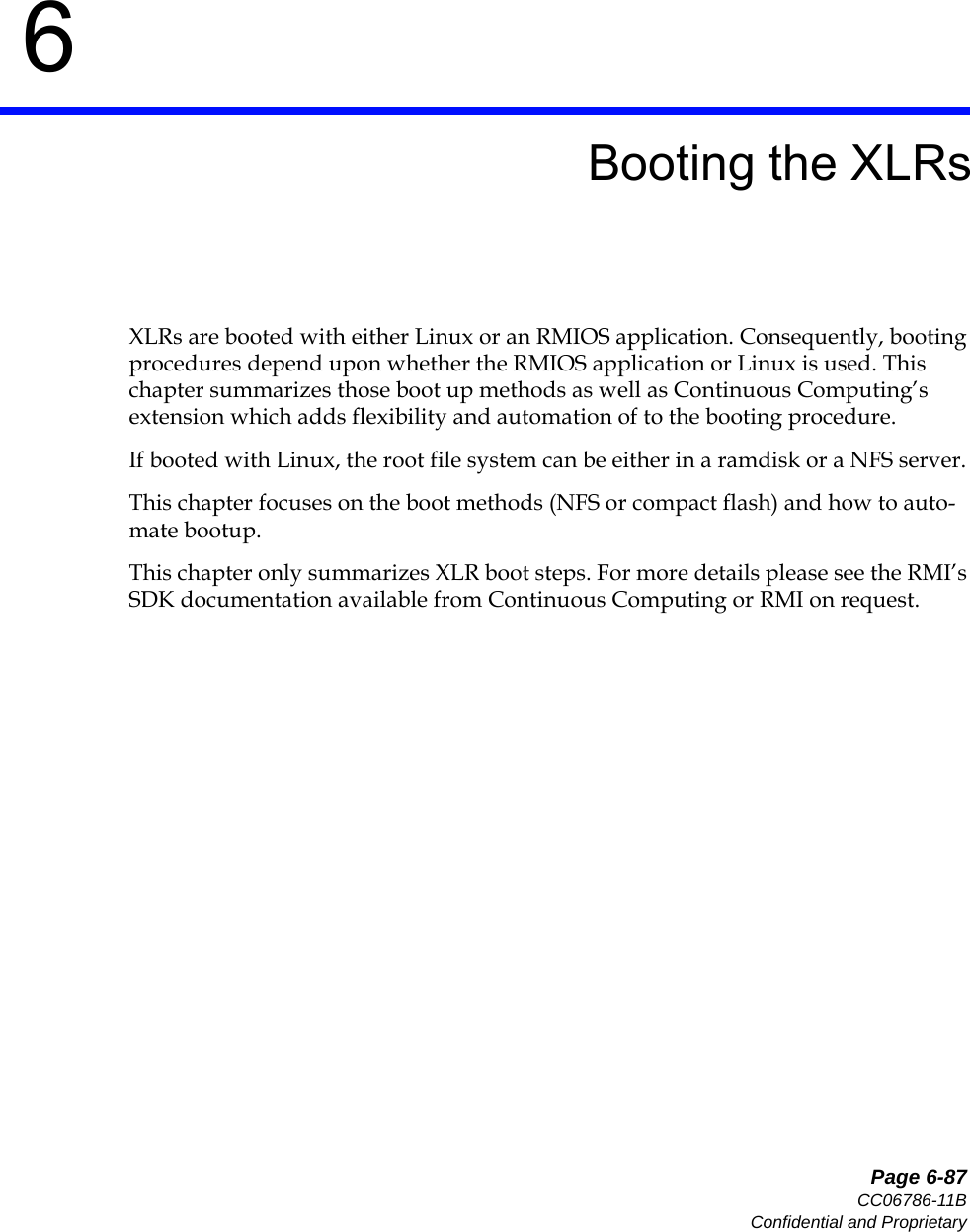
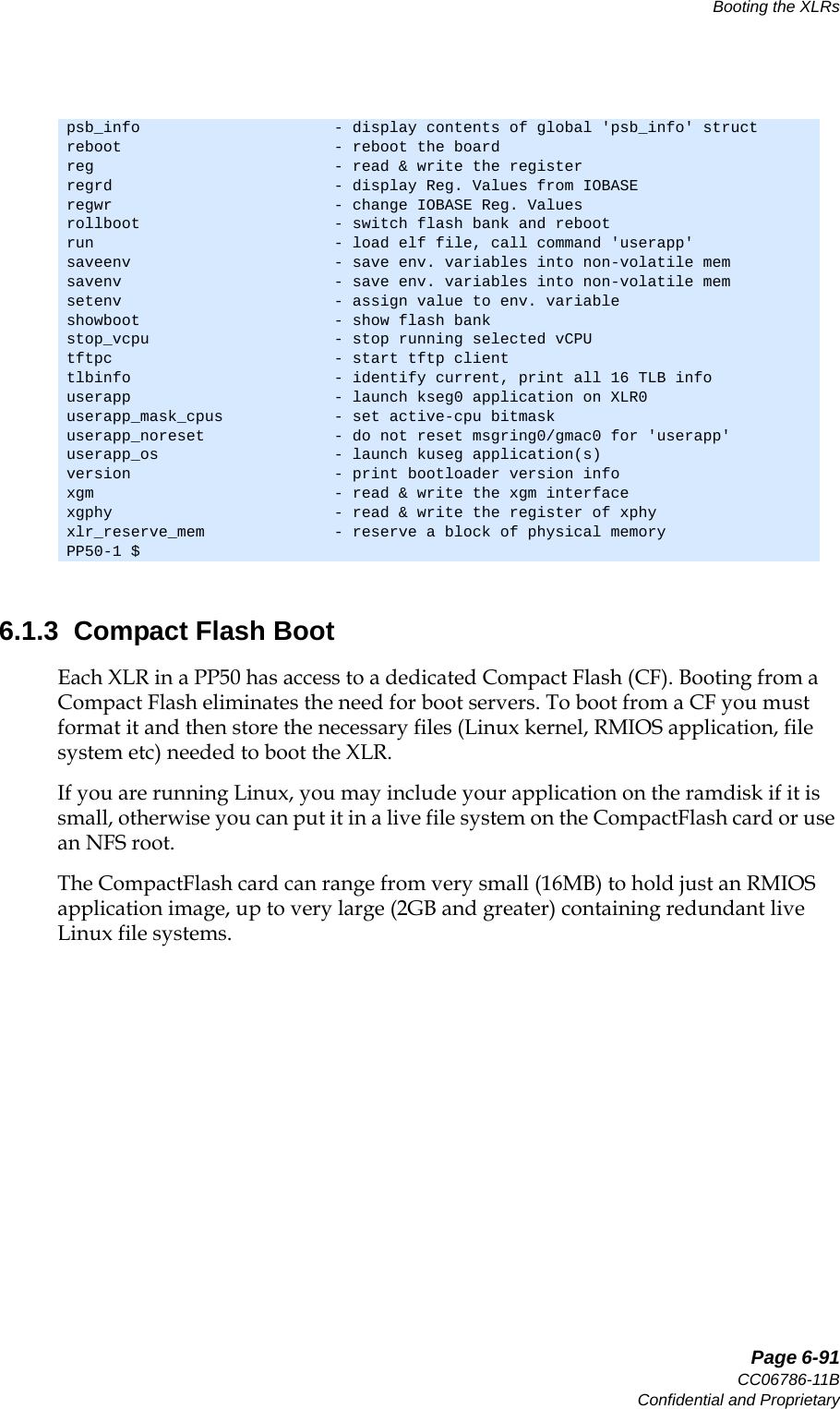
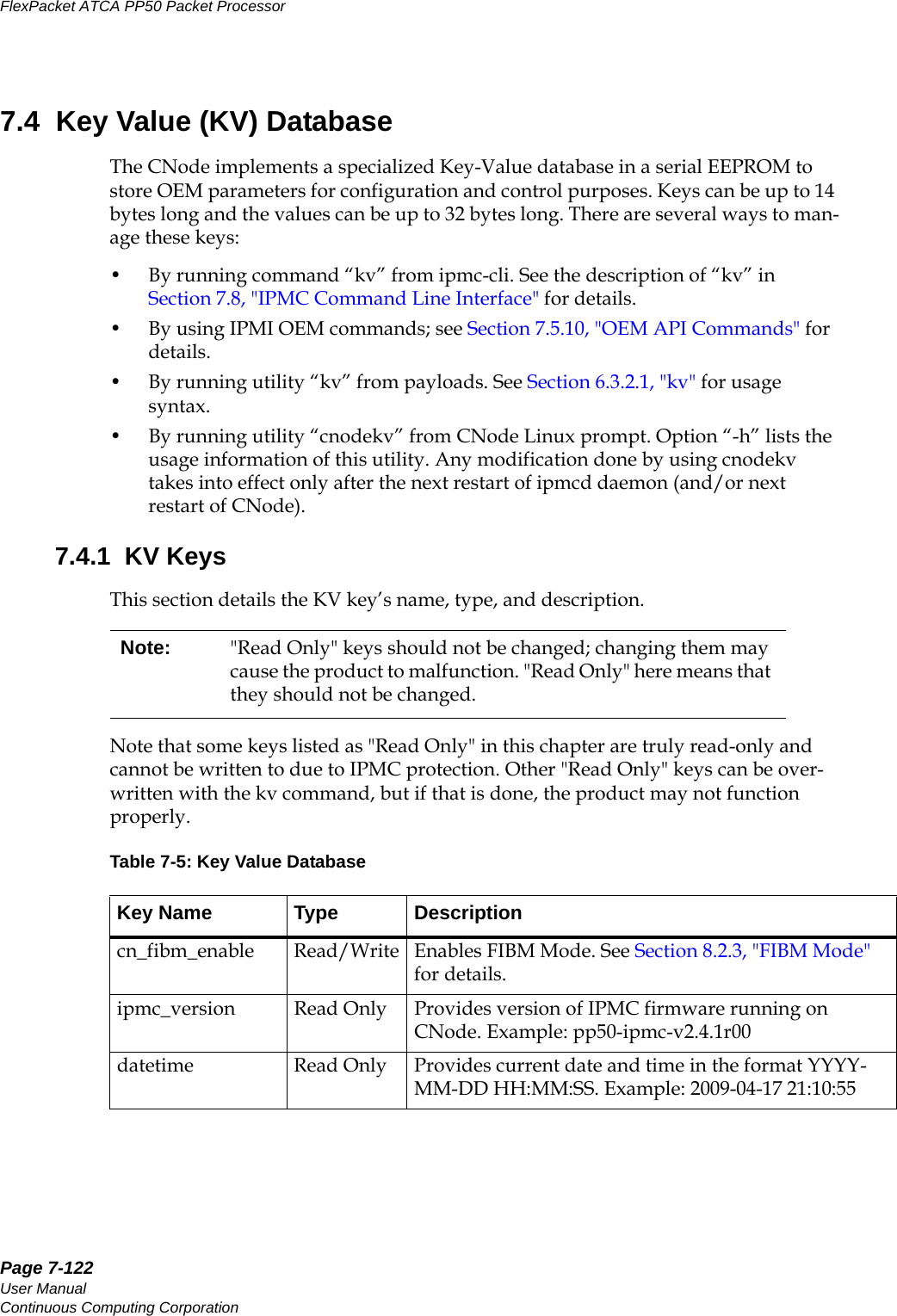
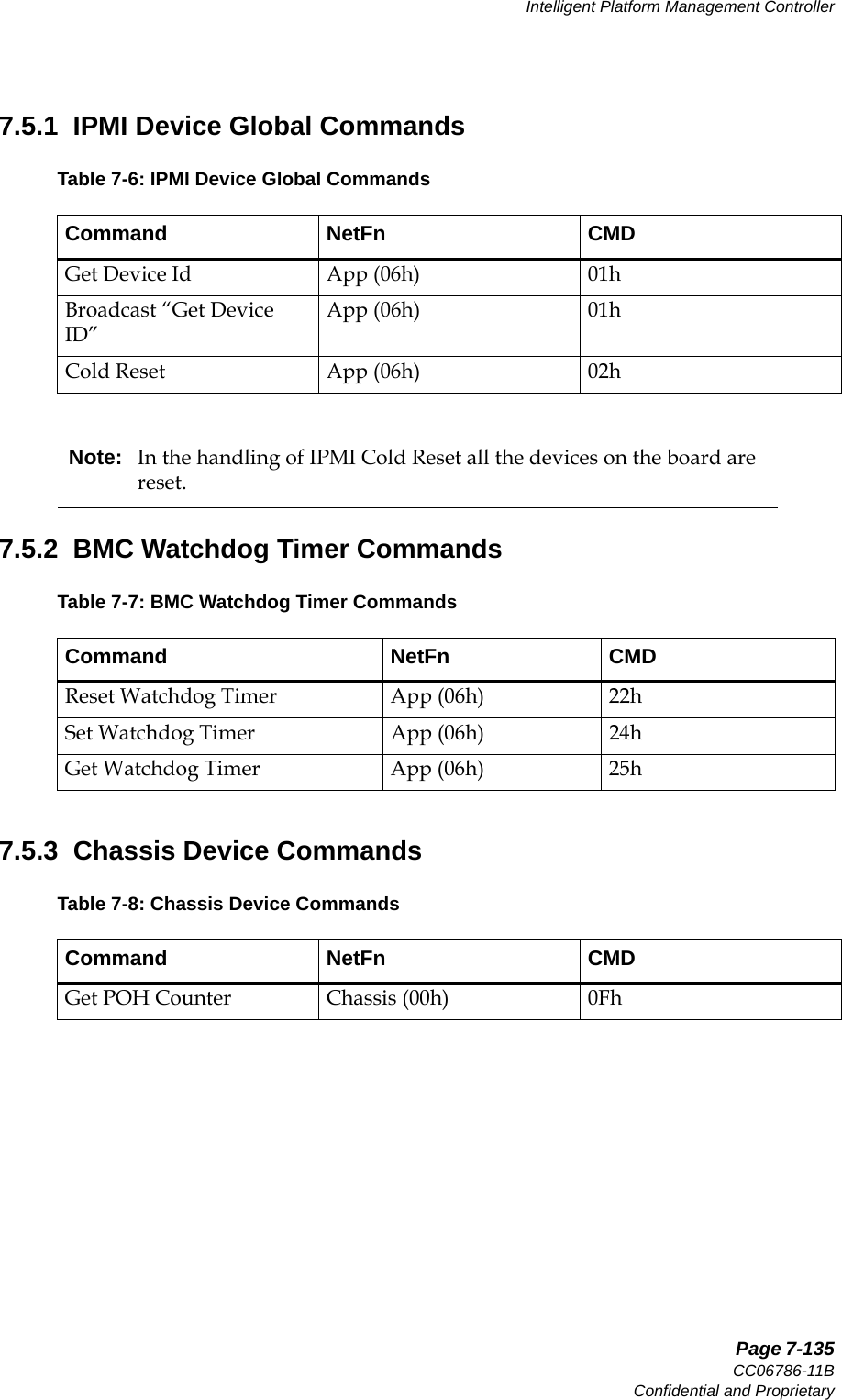
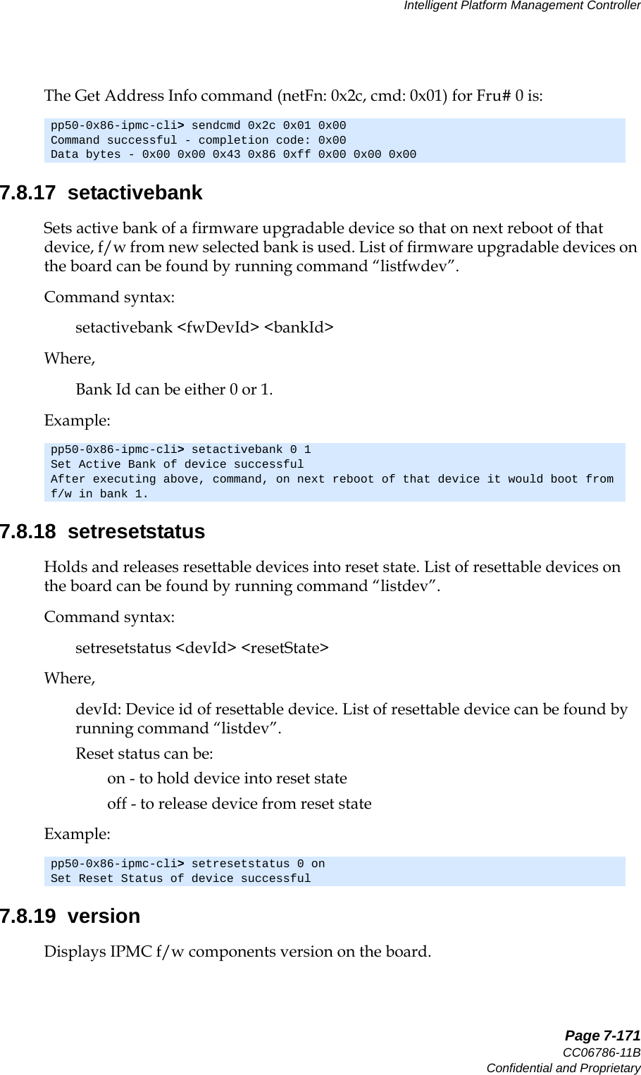
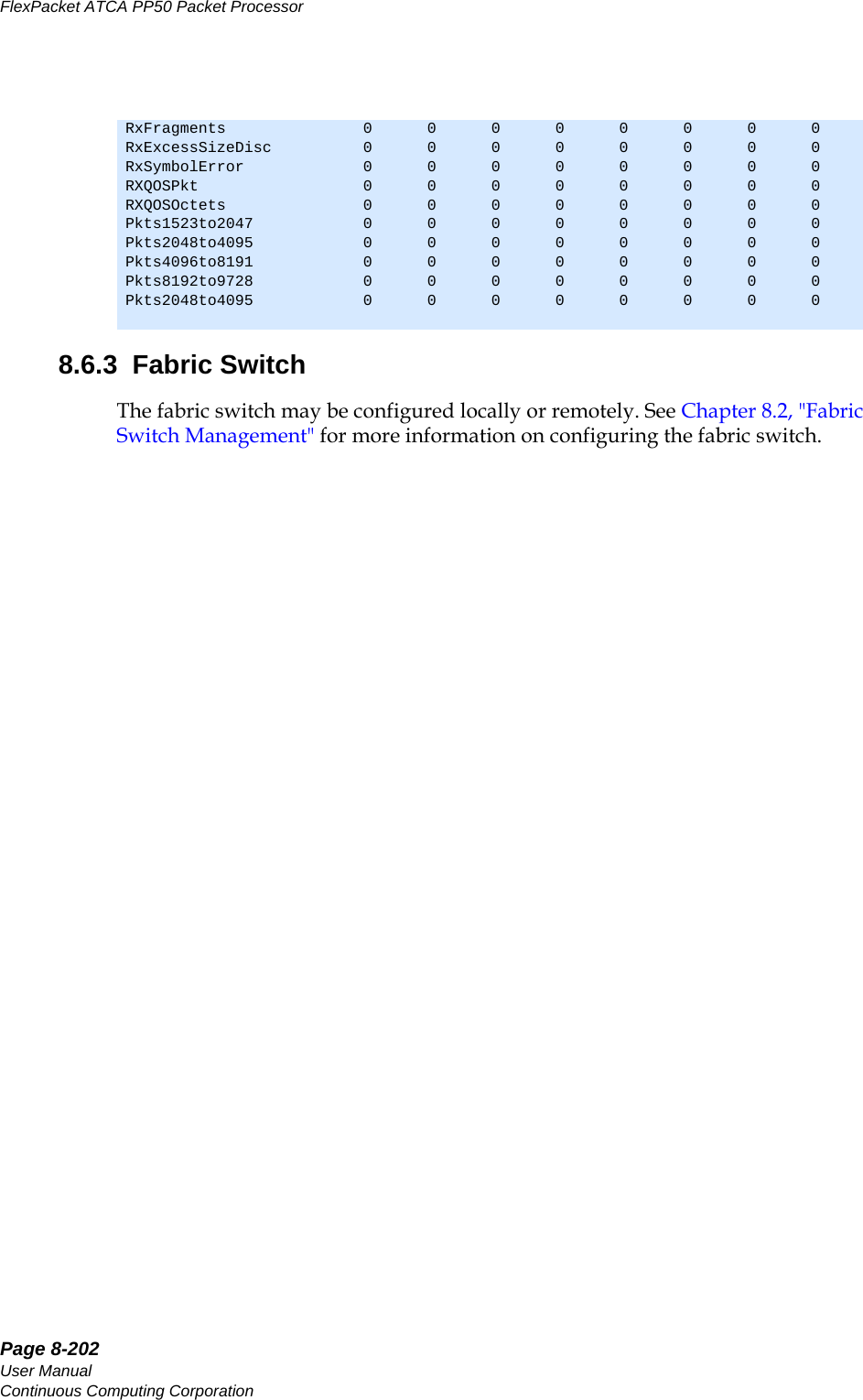
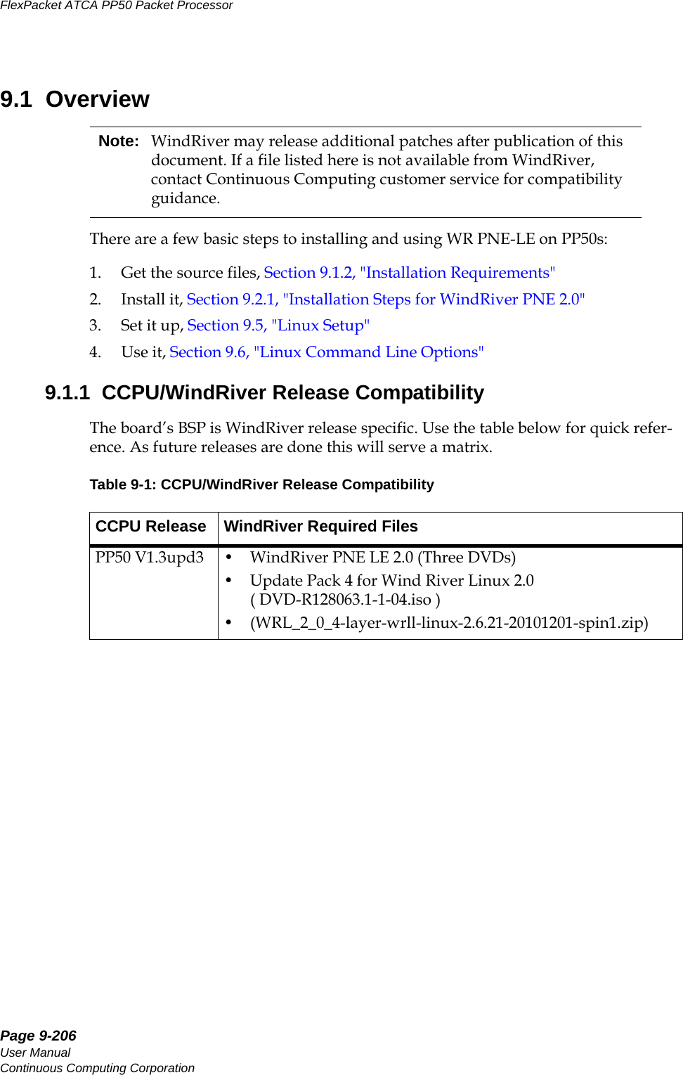
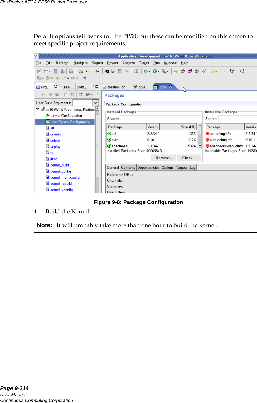
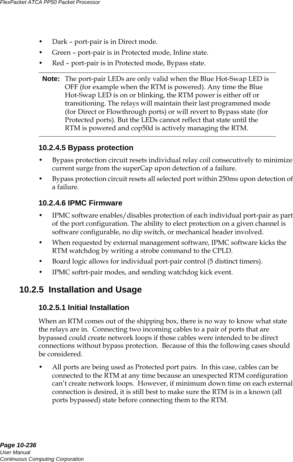
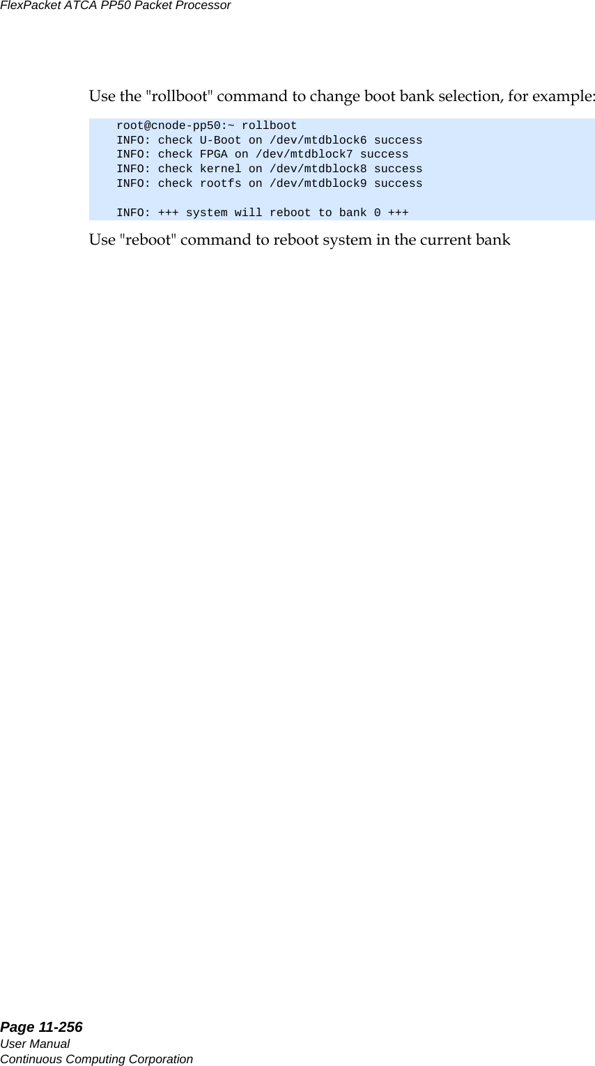
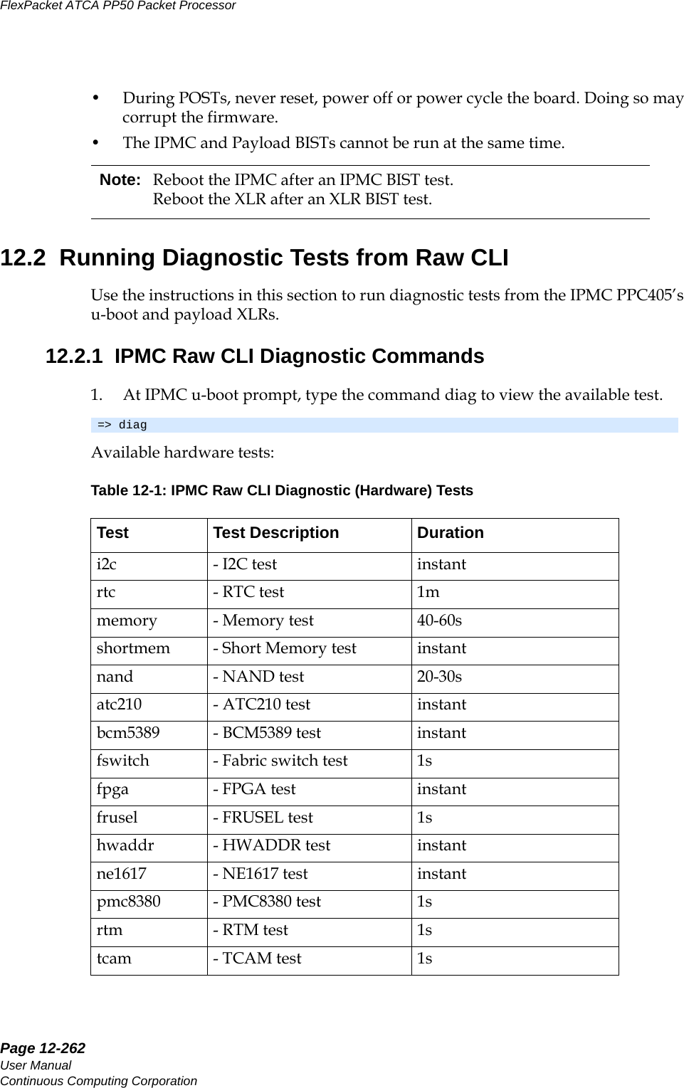
![Page 2-37CC06786-11BConfidential and ProprietaryTechnical Overview14ABABPreliminaryPossible operating modes for the switch are listed in Table 2-2 "Ethernet Switch Operating Modes". The fabric interface to the AdvancedTCA backplane can be configured for 10GbE or four 1GbE operation. In 10GbE operation, Ports 7 and 5 are wired to all 4 ports in channels 1 and 2. In four 1GbE operation, Ports 7 and 5 are put in 1GbE mode and make up port [a] of the fabric interface. Switch ports [15 19 13] make up ports [b c d] for channel 1, and likewise switch ports [21 11 9] make up ports [b c d] for Fabric channel 2. The current allocation of the Fabric Ethernet ports are listed inTable 2-3 "Ethernet Switch Port Usage".Table 2-2: Ethernet Switch Operating ModesPort Lanes Speed Mode1 – 8 4 3.125GHz 10GbE1 – 8 1 3.125GHz 2.5GbE1 – 8 1 1.25GHz 1GbE9 – 24 1 1.25GHz 1GbETable 2-3: Ethernet Switch Port UsageInternal Switch Port Number-ingPort Number-ingPort Label-ing Speed Description1 10GbE RAZA12FP-XG1/RTM-XG110GbE Through a mux to RTM #1 or Front panel #13 10GbE RAZA1 10G-B 4FP-XG2/RTM-XG210GbE Through a mux to RTM #2 or Front panel #25 10GbE Fabric Chan 26 10GbE RAZA2 10G-A7 10GbE Fabric Chan 18 10GbE RAZA2 10G-B 9 1GbE Fabric Chan 2 Port D10 17 RTM #3 1GbE 1GbE port11 1GbE Fabric Chan 2 Port C12 18 RTM #4 1GbE 1GbE port13 1GbE Fabric Chan 1 Port D](https://usermanual.wiki/UTStarcom/MSG2000/User-Guide-2403206-Page-35.png)
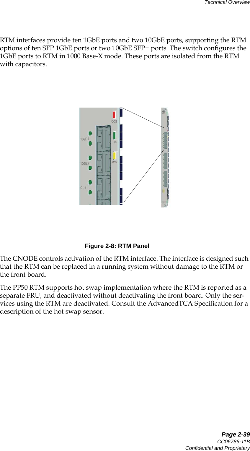
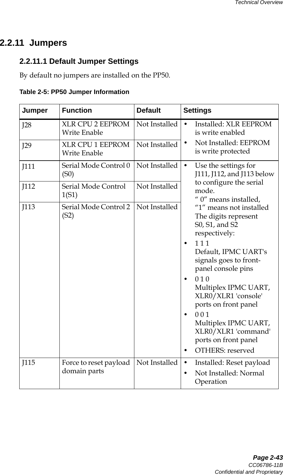
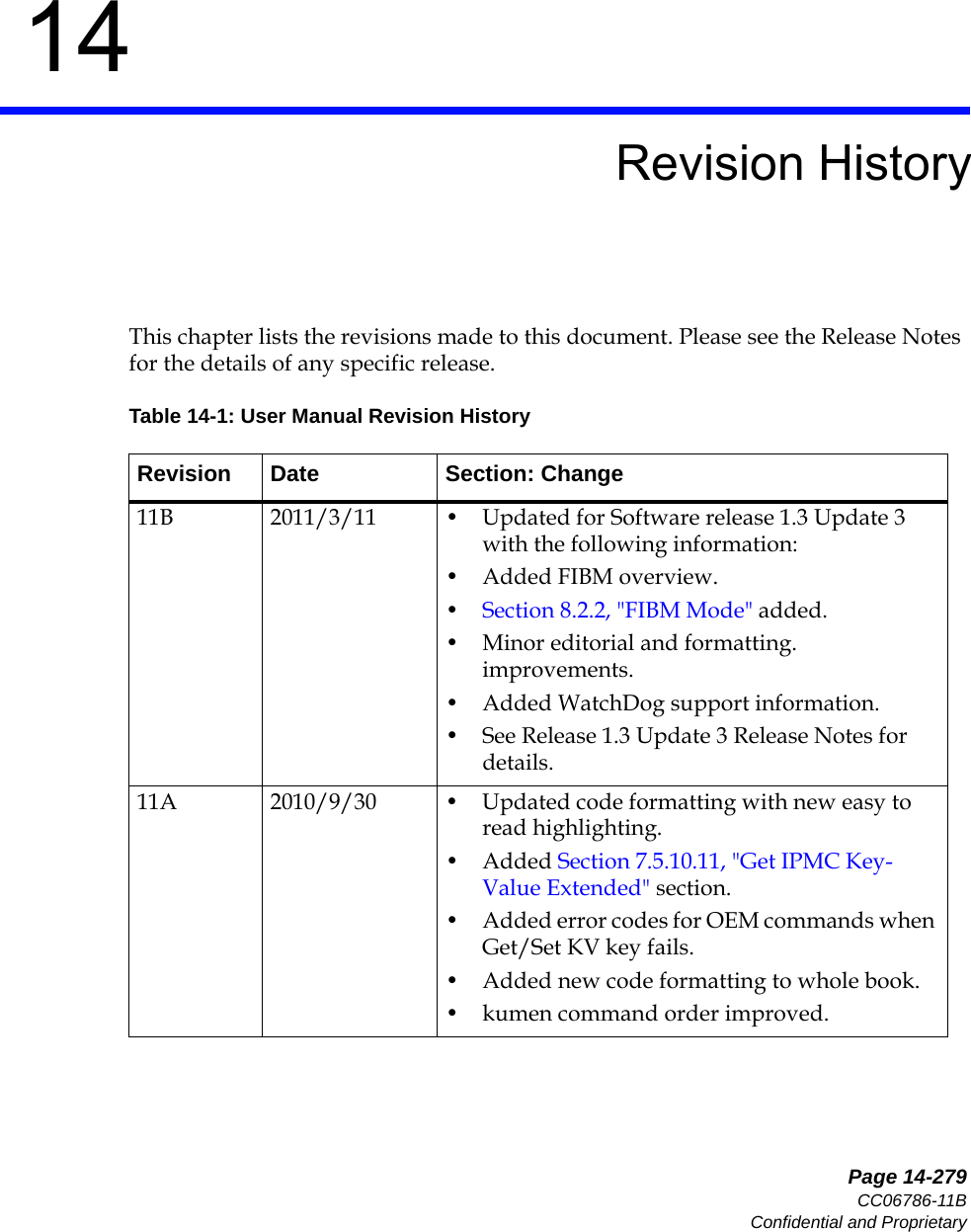
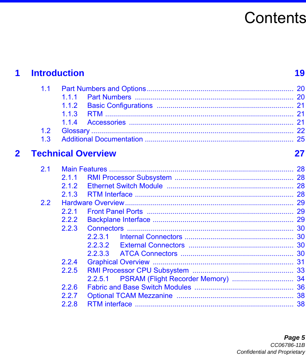
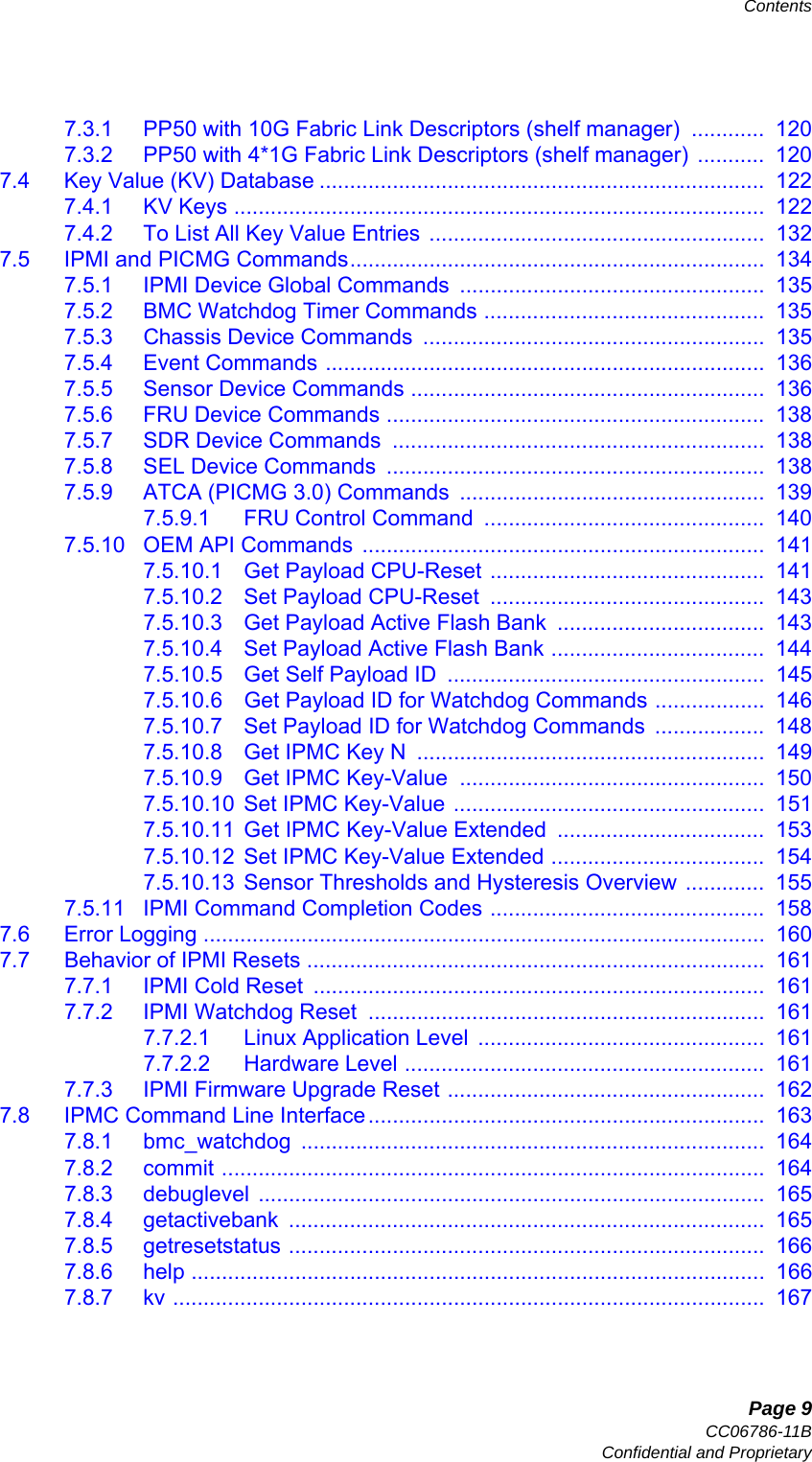
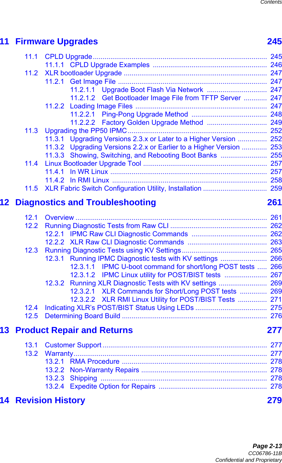
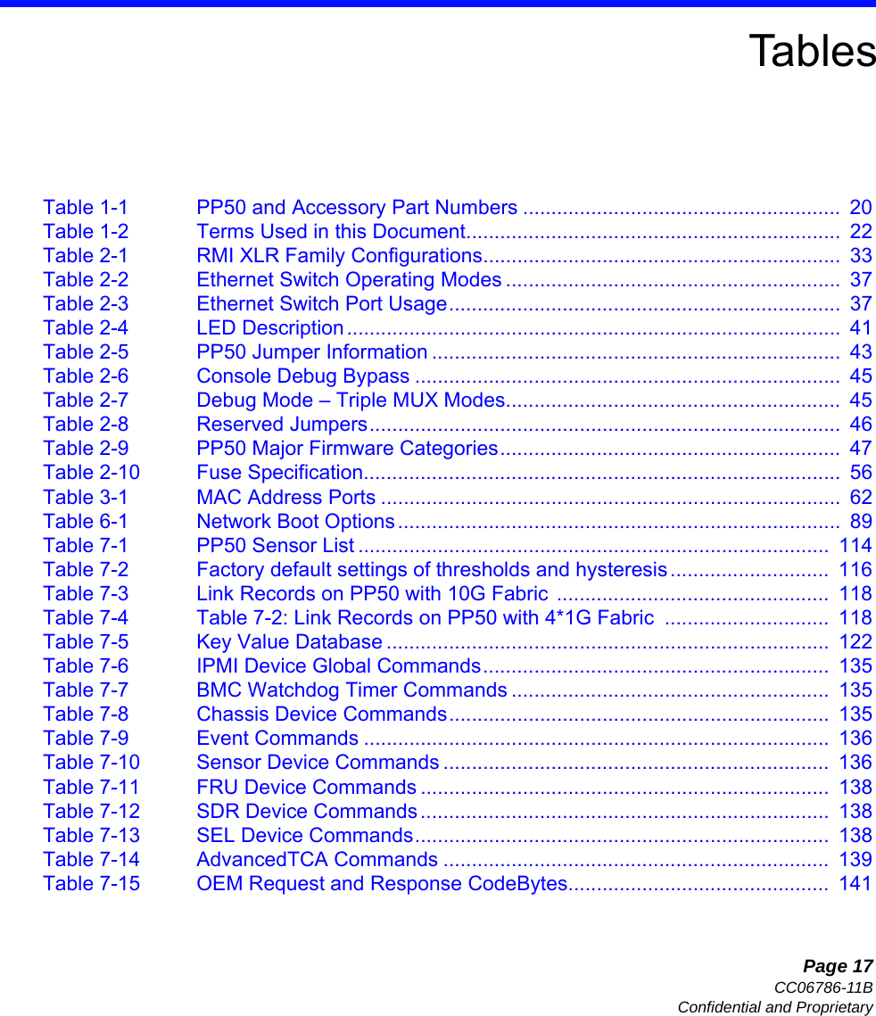
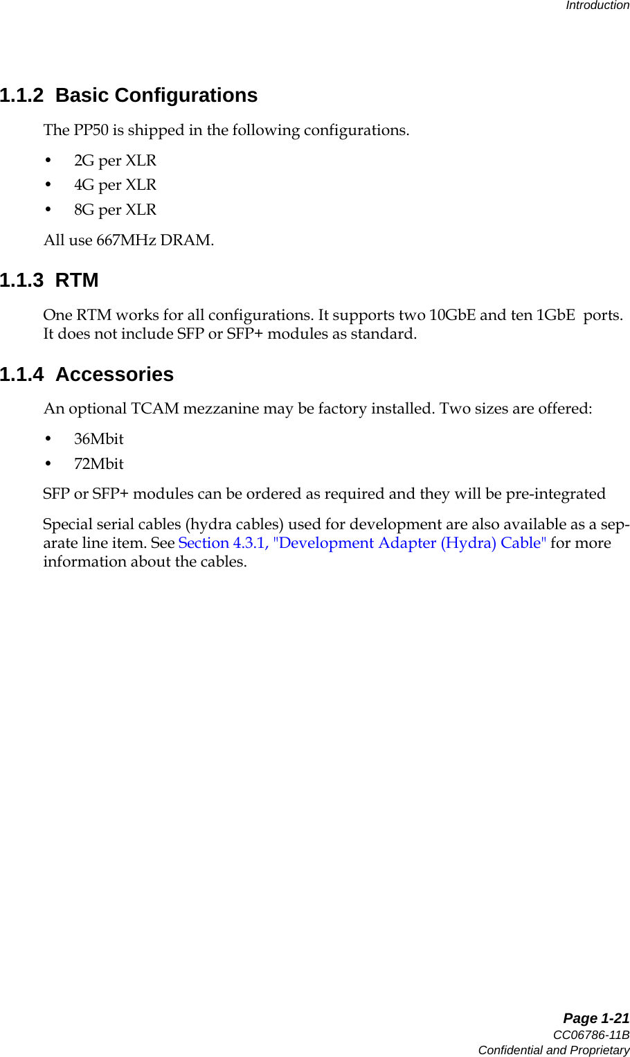
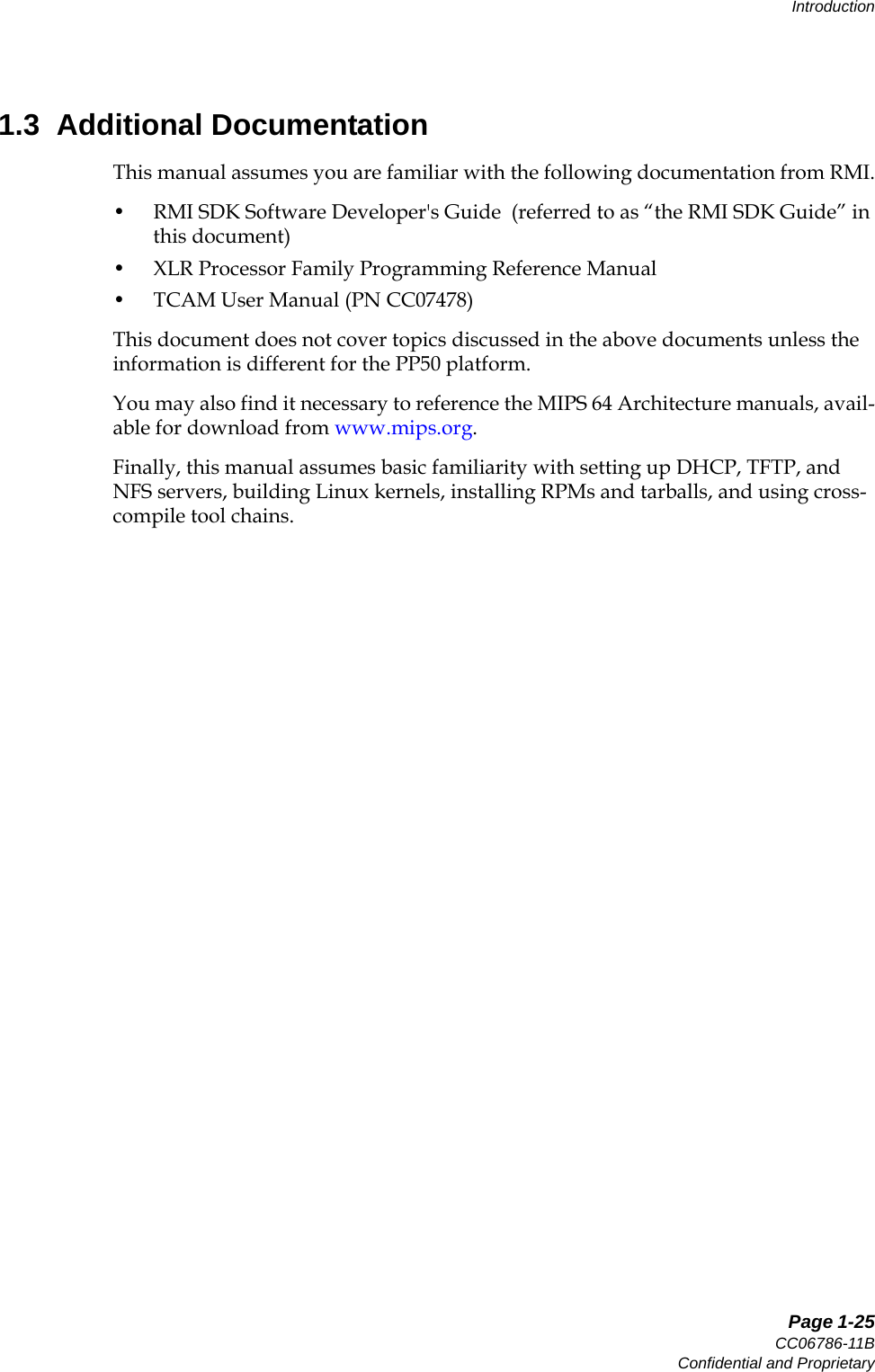
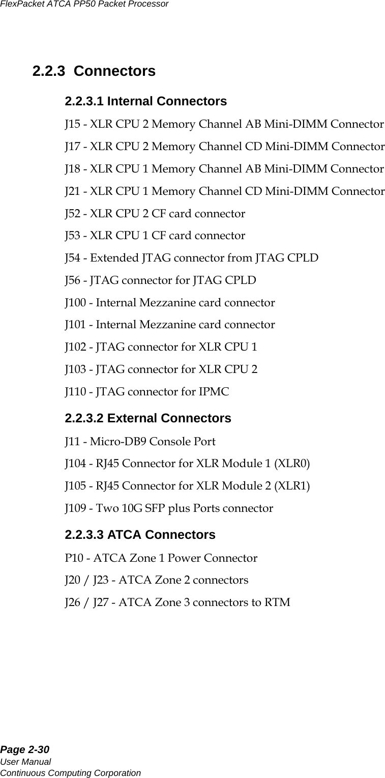
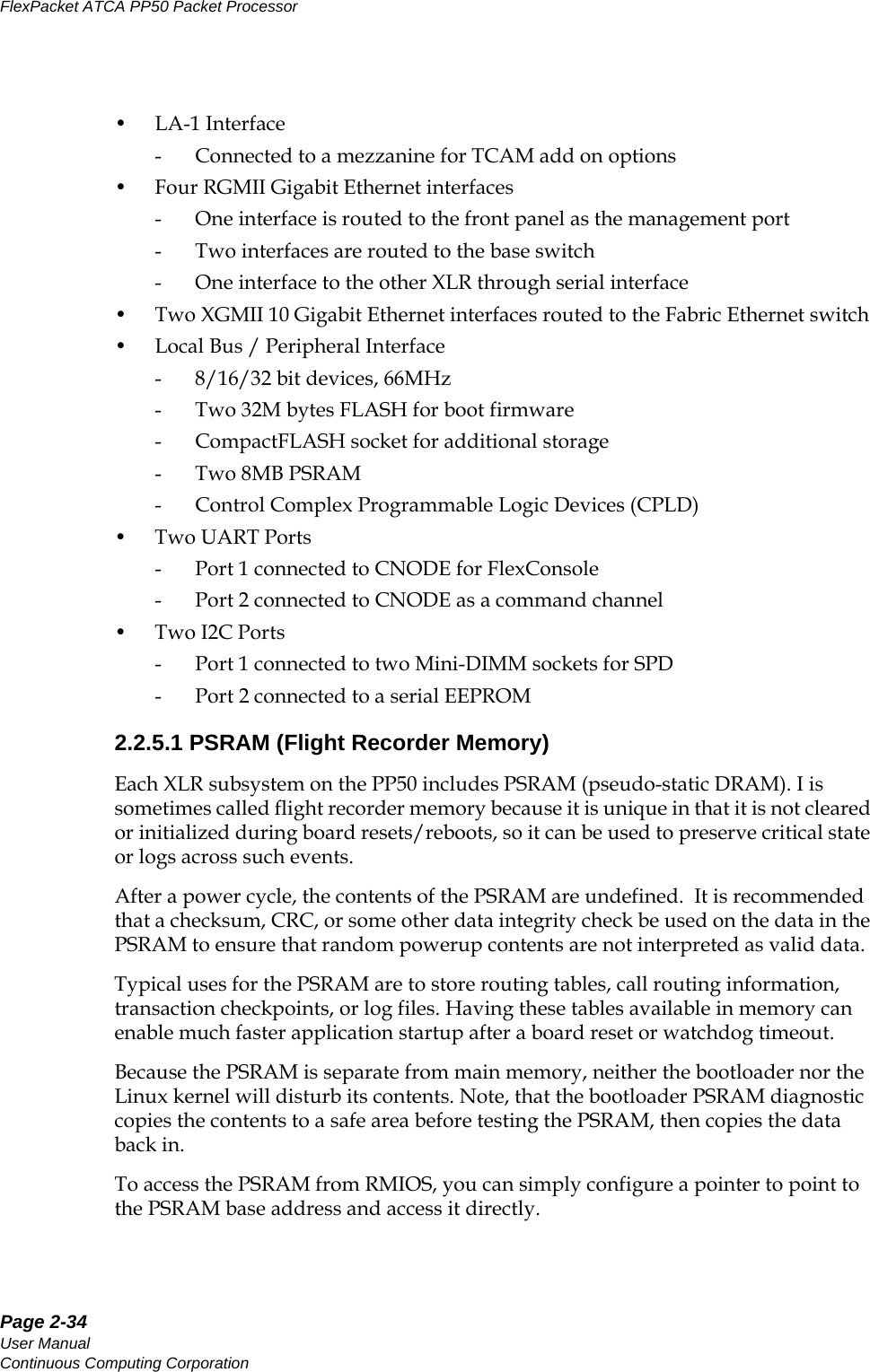
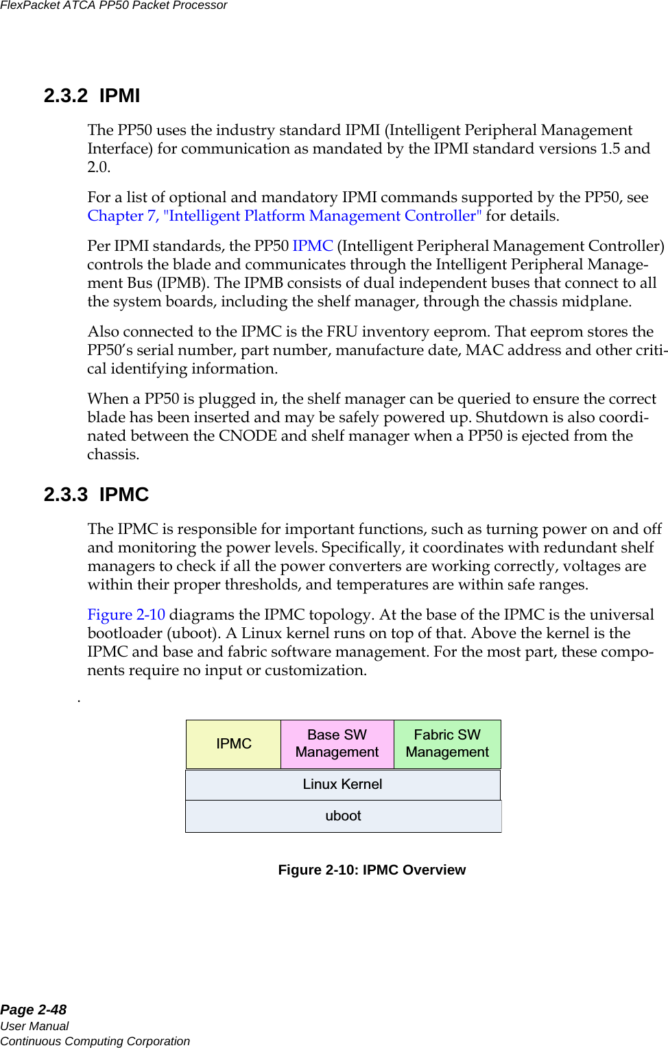
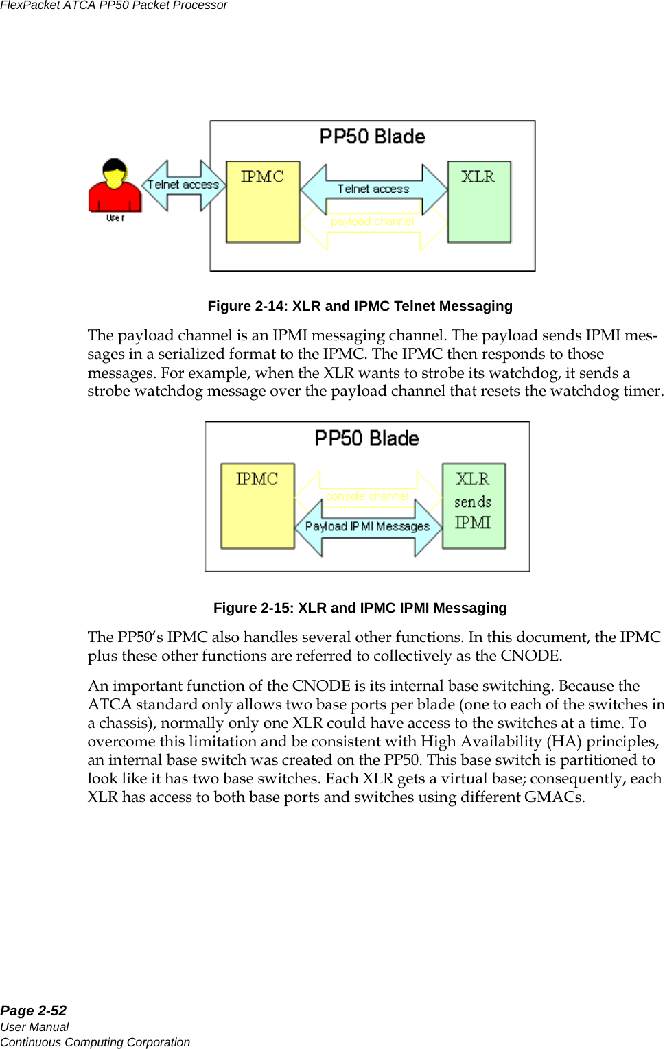
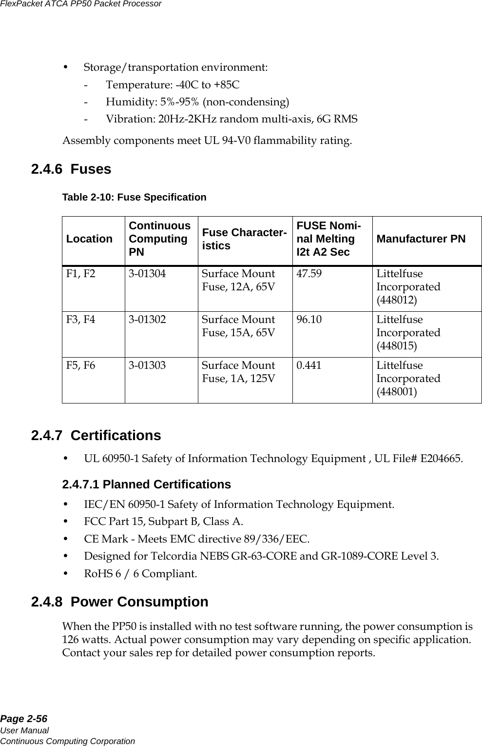
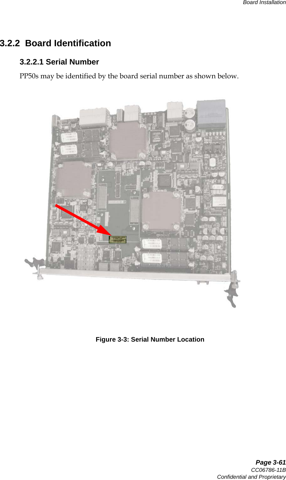
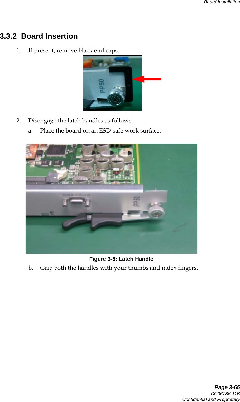
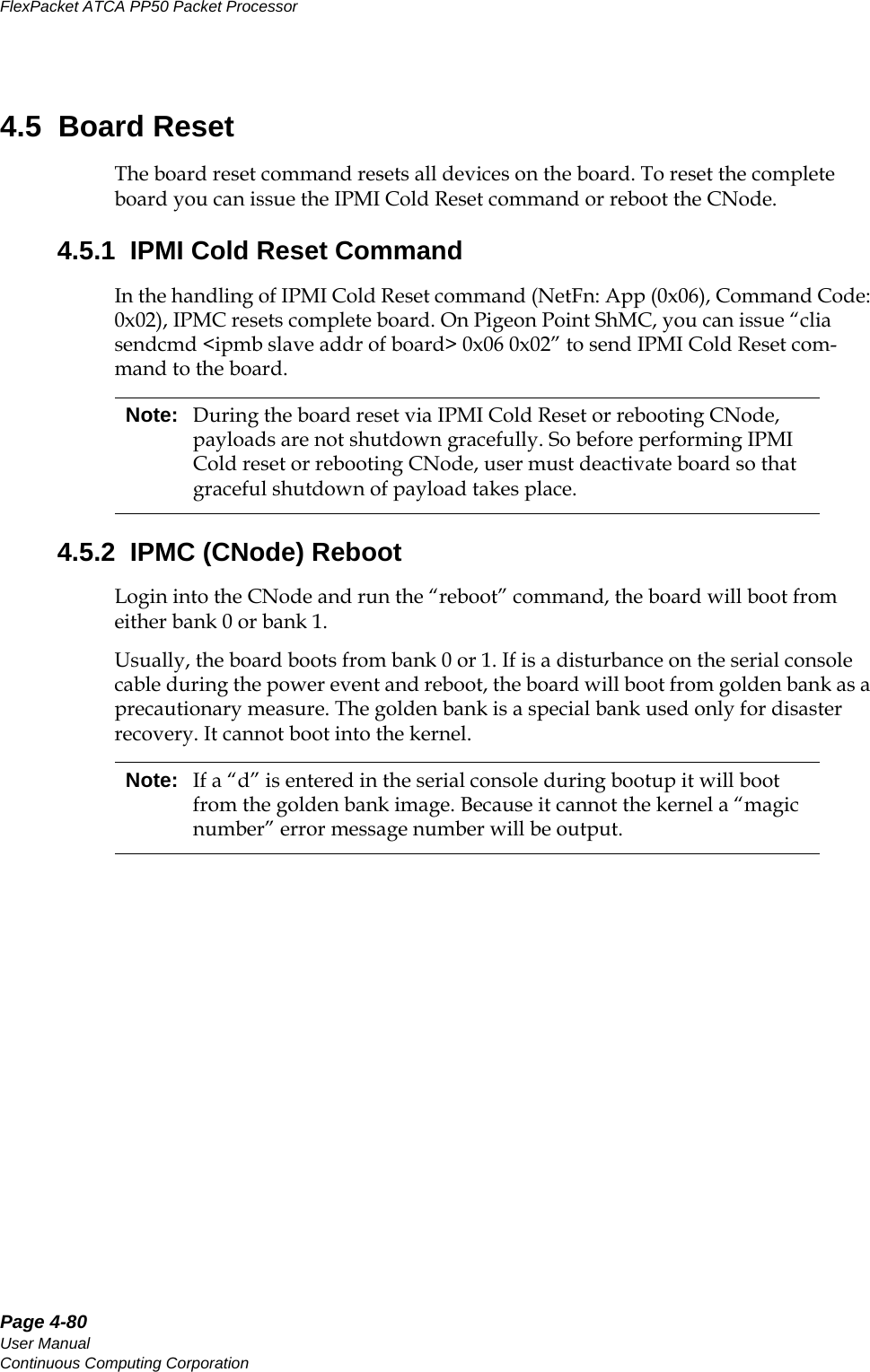
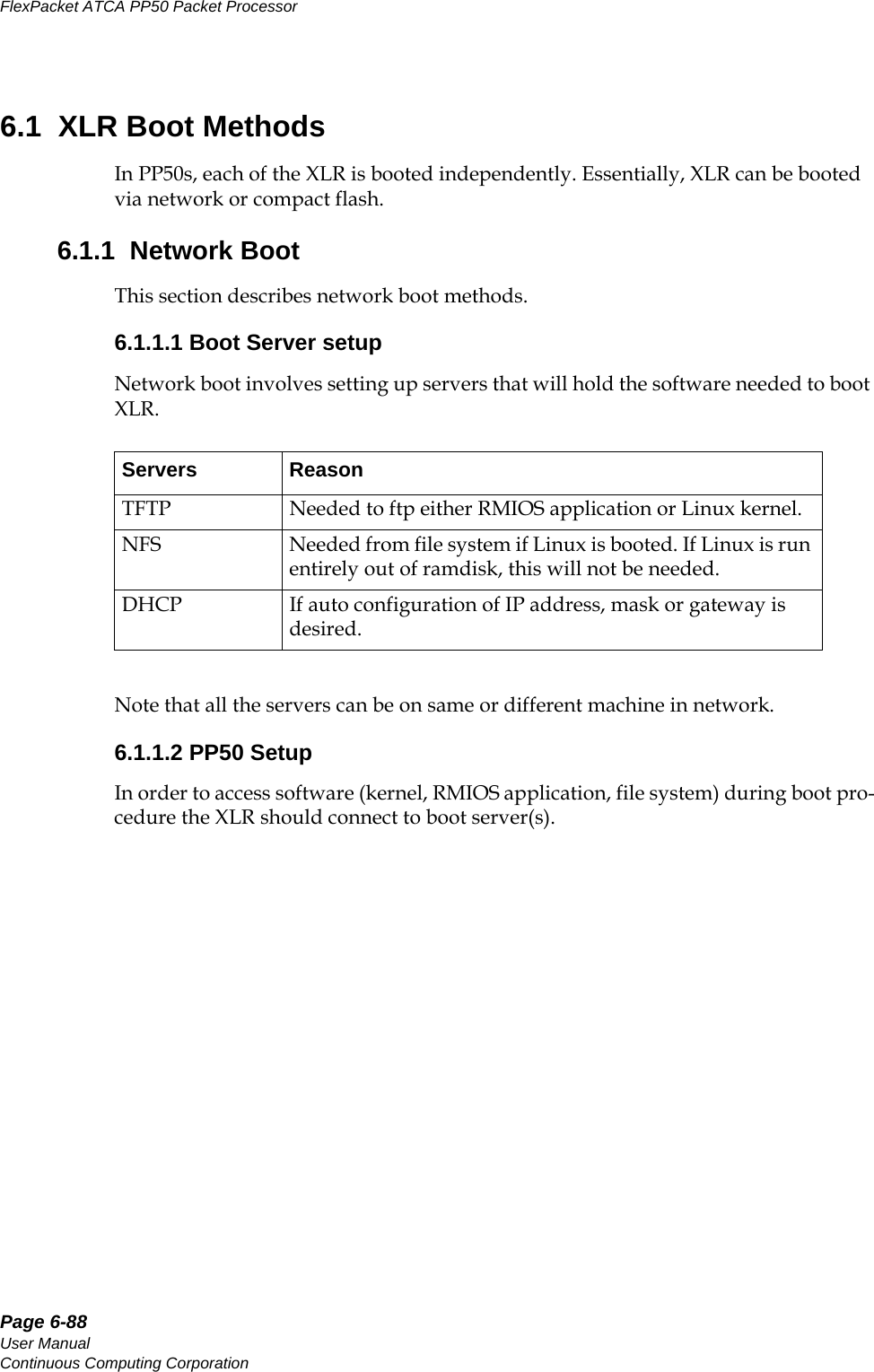
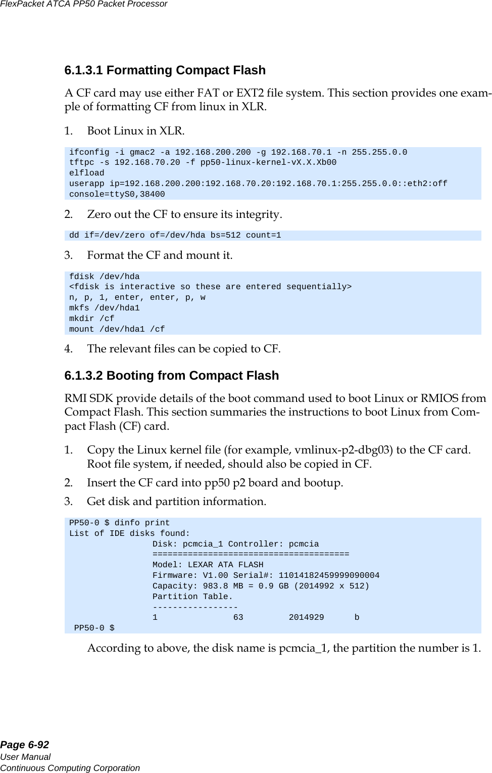
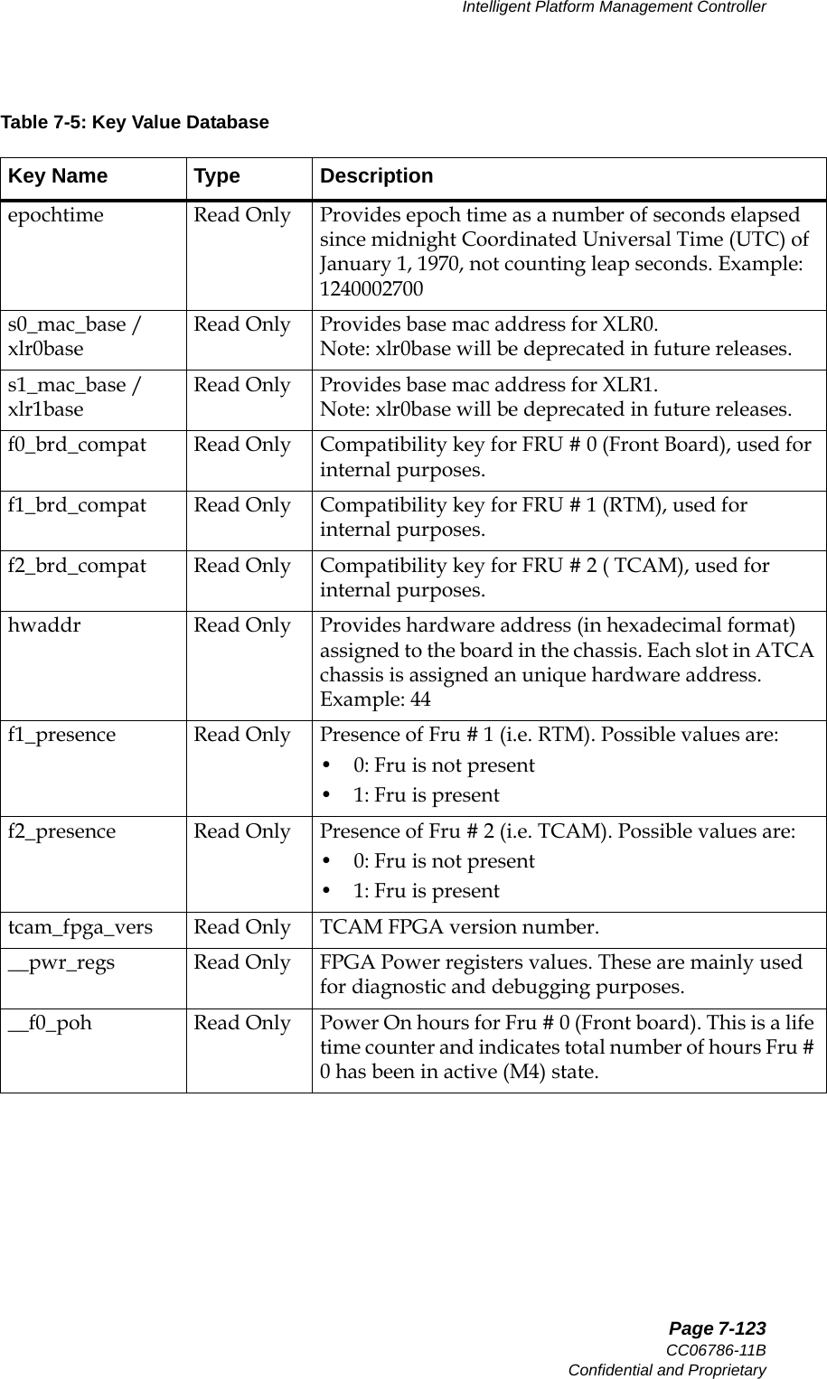
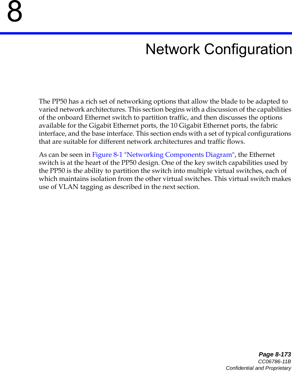
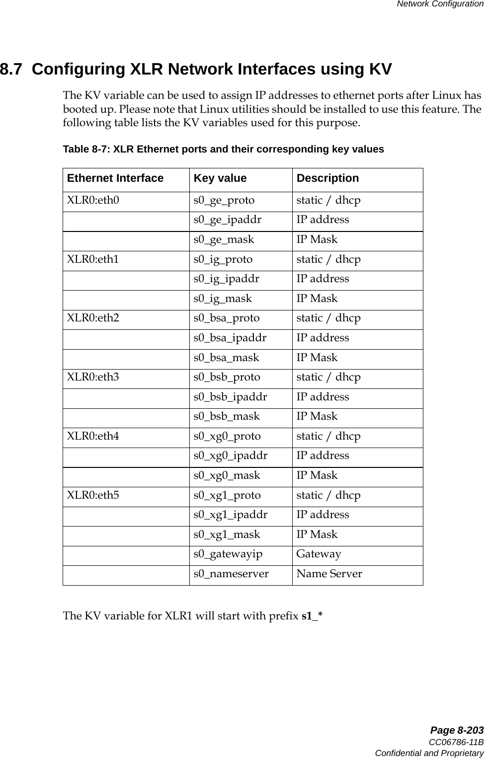
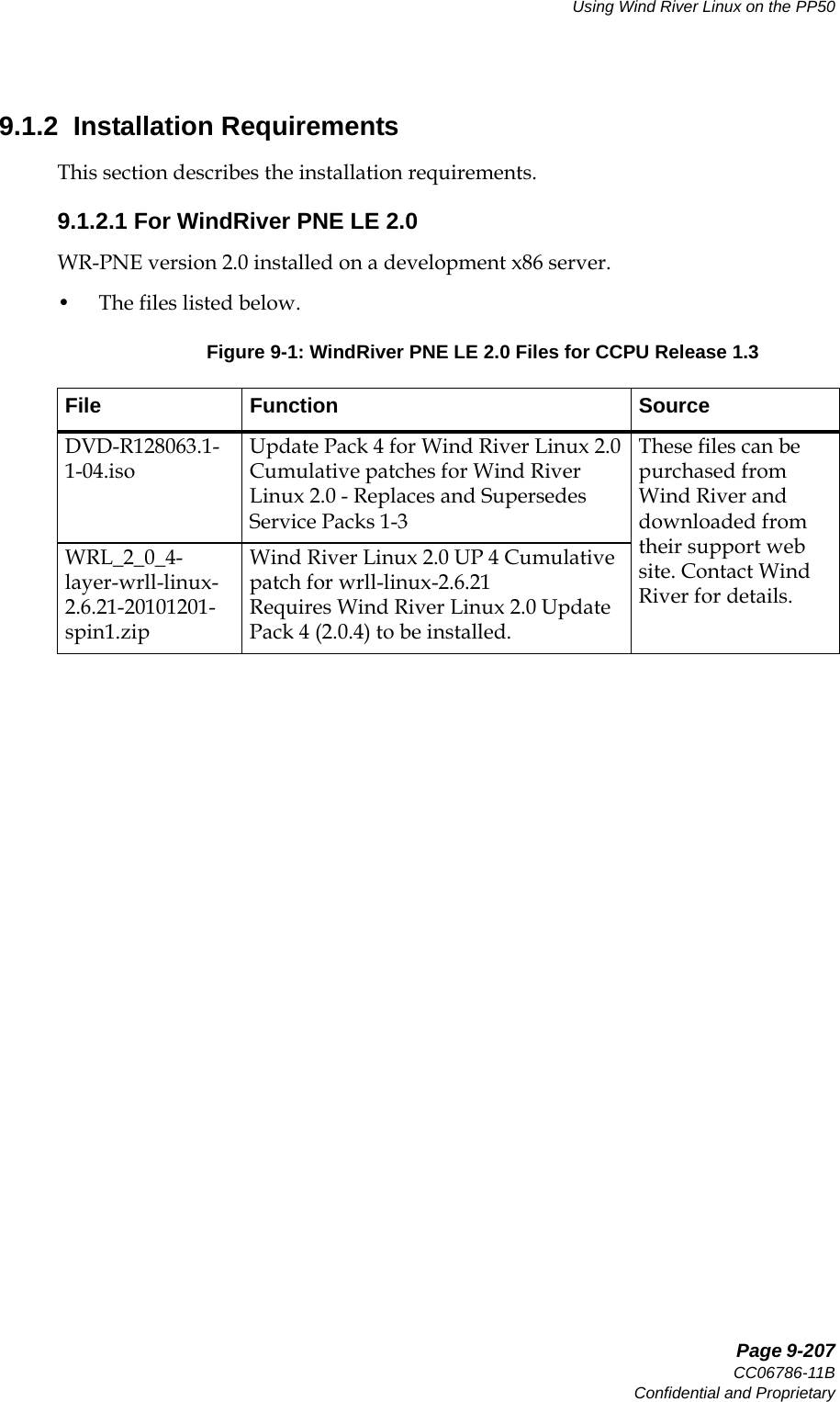
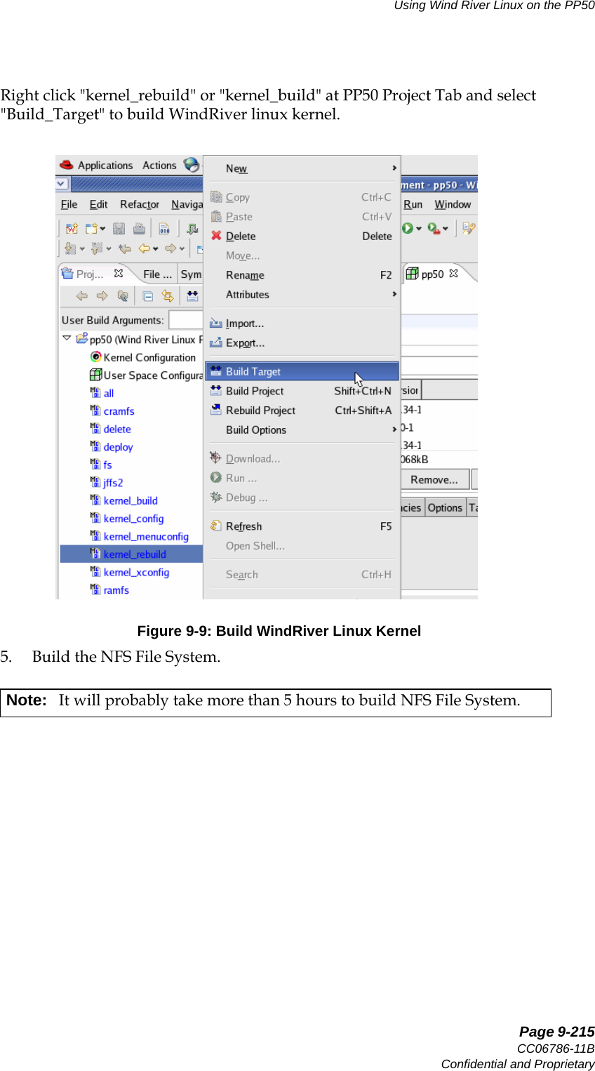
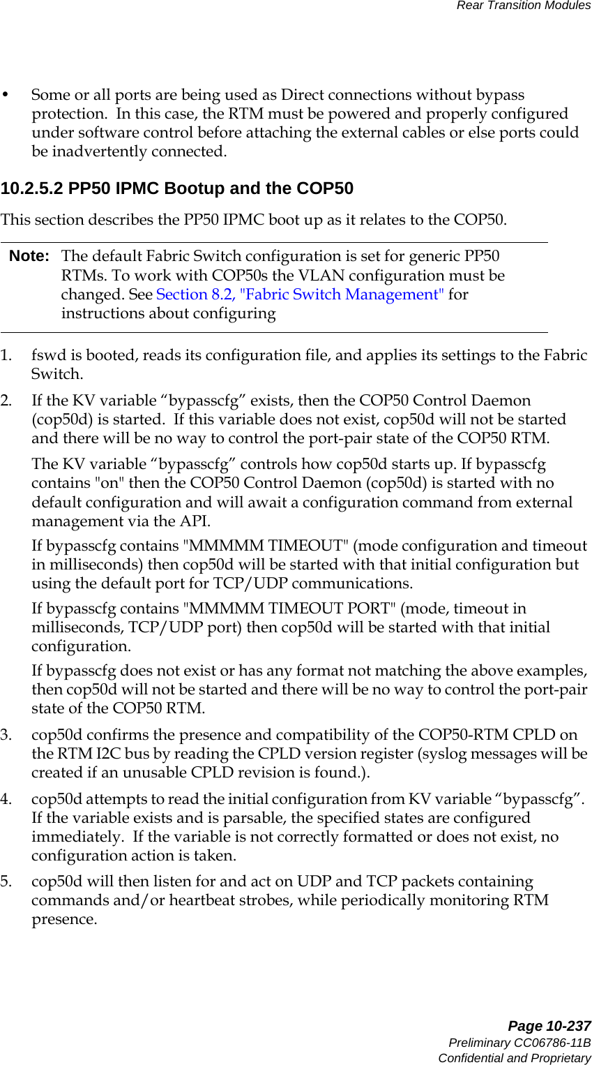
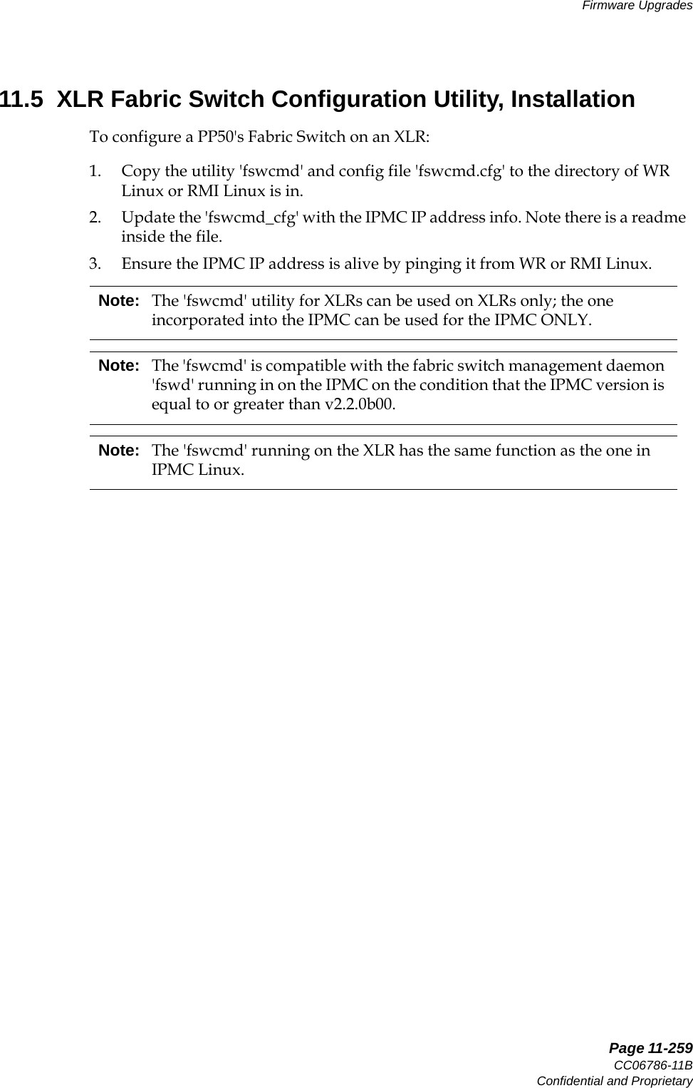
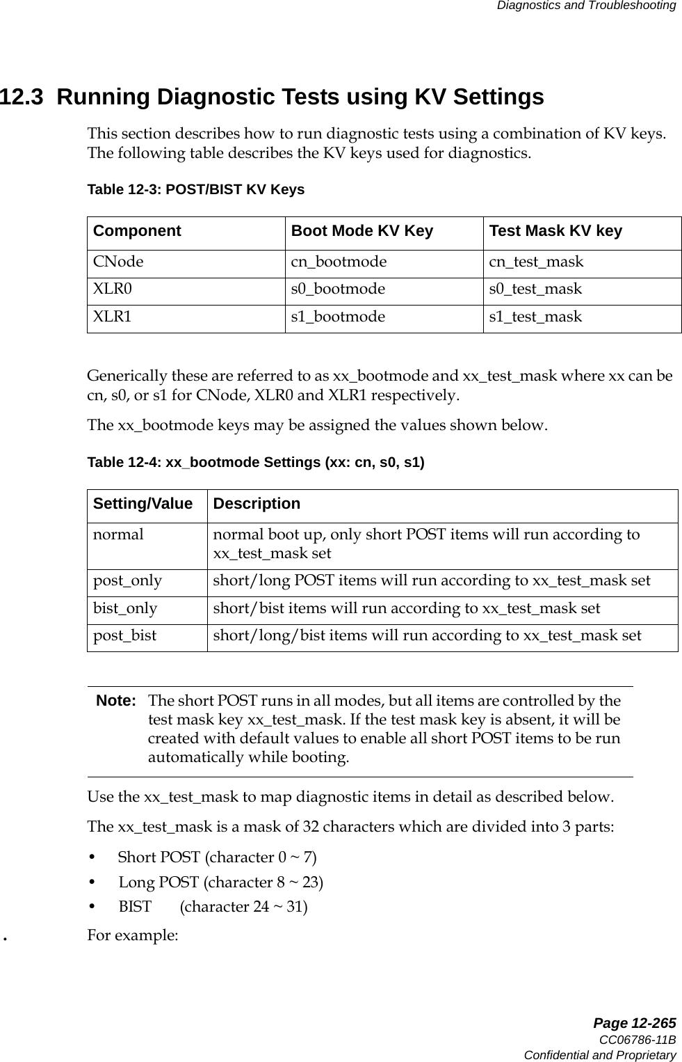
![Page 2-44User ManualContinuous Computing CorporationFlexPacket ATCA PP50 Packet Processor Preliminary2.2.11.2 Force Power On Jumper: J116By default this jumper is open and the power is controlled by the CNODE. The pri-mary 12V power turns on as soon as A_OK or B_OK is true indicating that one of the 48V feeds is in range. When the jumper is installed, the secondary power turns on as soon as the primary 12V is in range. This is regardless of the state of any CNODE control. Also, the sec-ondary fault latch-off feature is disabled so the board will remain powered even if one of the supplies is not in range. This feature should be used carefully.J116 Force Payload Power OnNot Installed • Installed: Force blade power on [ignores IPMC]• Not Installed: Normal operation - IPMC controls power on/offJ117 Select XLR0 Boot Flash BankNot Installed • Installed: XLR0 boot from the first bank• Not Installed: XLR0 boot from the second bankJ118 Select XLR1 Boot Flash BankNot Installed • Installed: XLR1 boot from the first bank• Not Installed: XLR1 boot from the second bankJ119 Force to reset CNODE moduleNot Installed • Installed: Reset CNODE module parts• Not Installed: Normal OperationTable 2-5: PP50 Jumper InformationJumper Function Default Settings](https://usermanual.wiki/UTStarcom/MSG2000/User-Guide-2403206-Page-42.png)
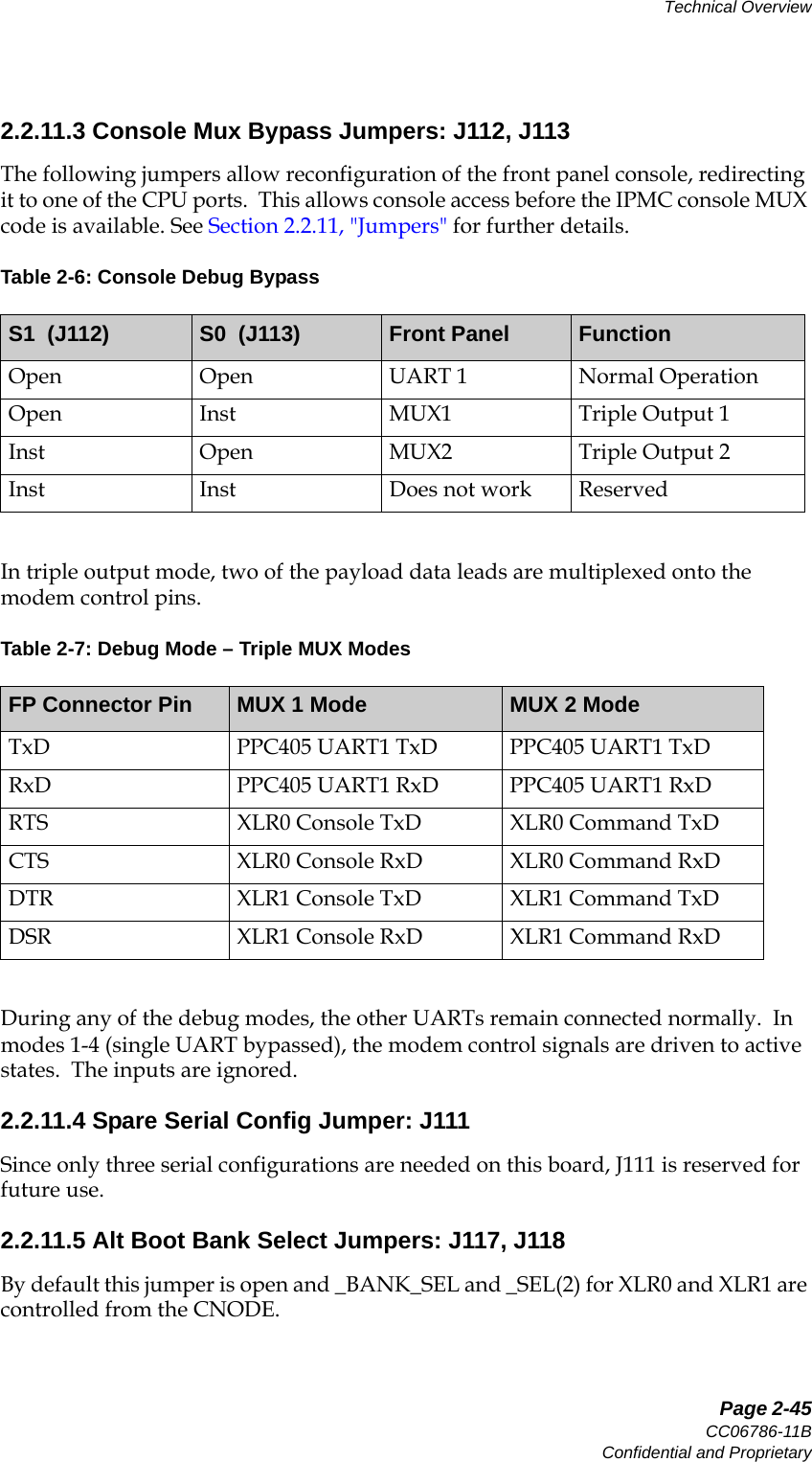
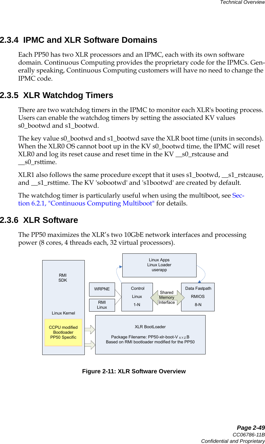

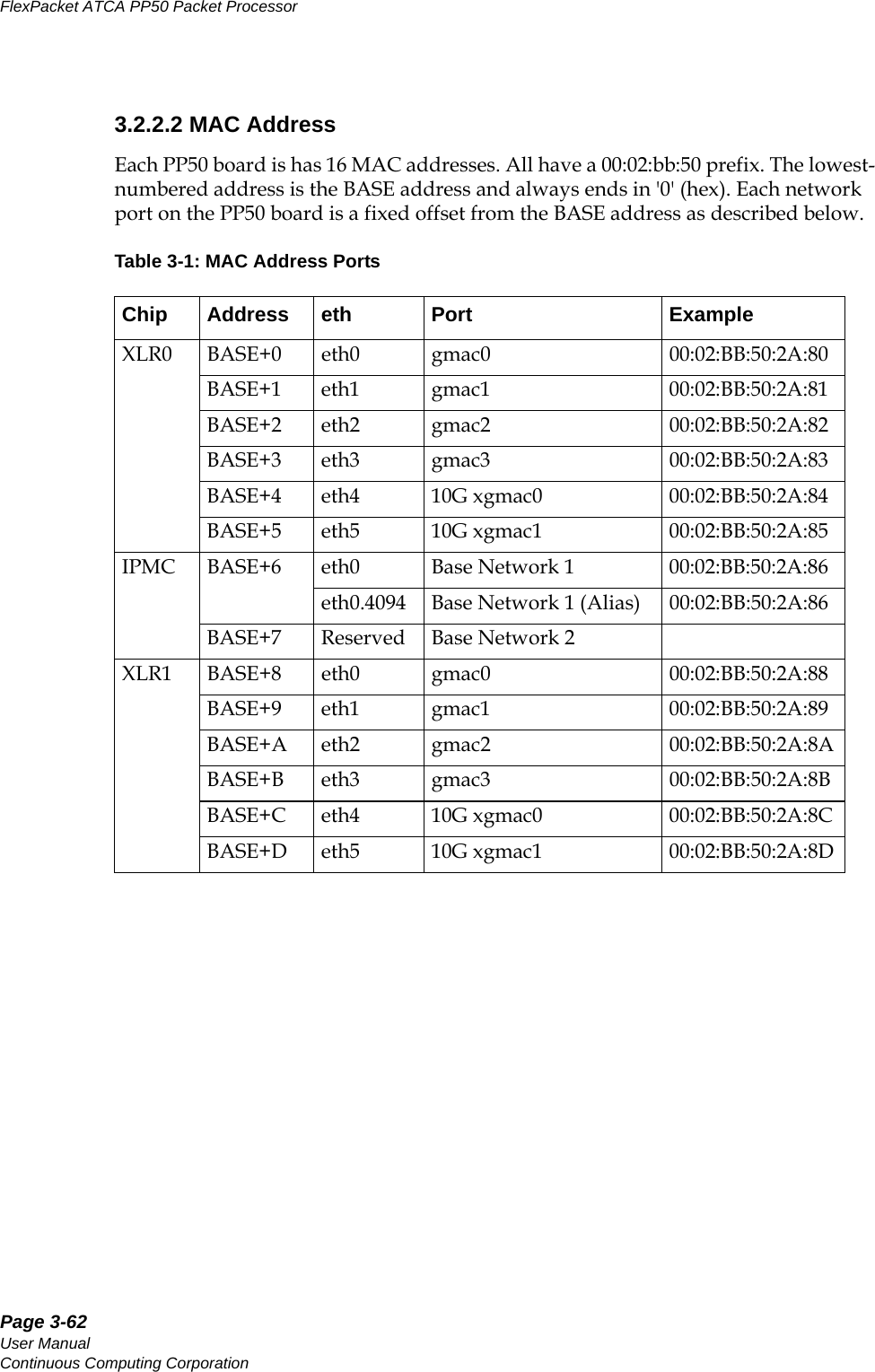
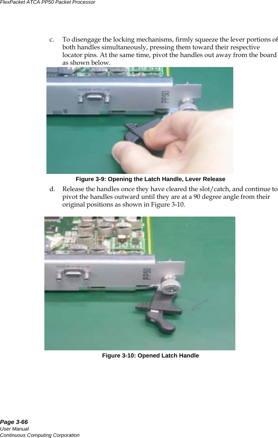
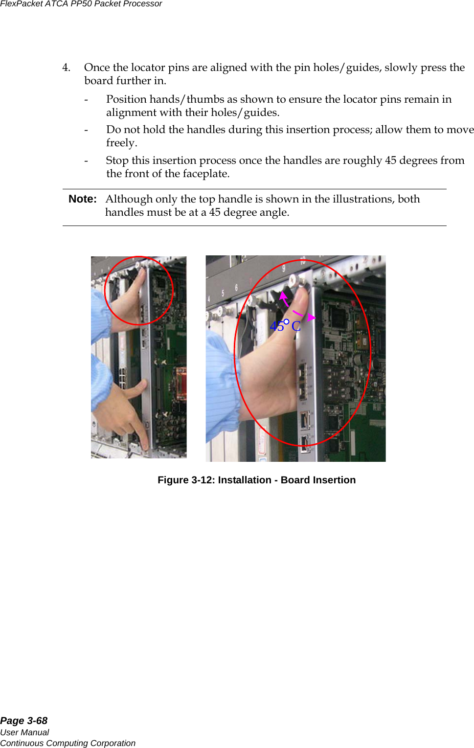
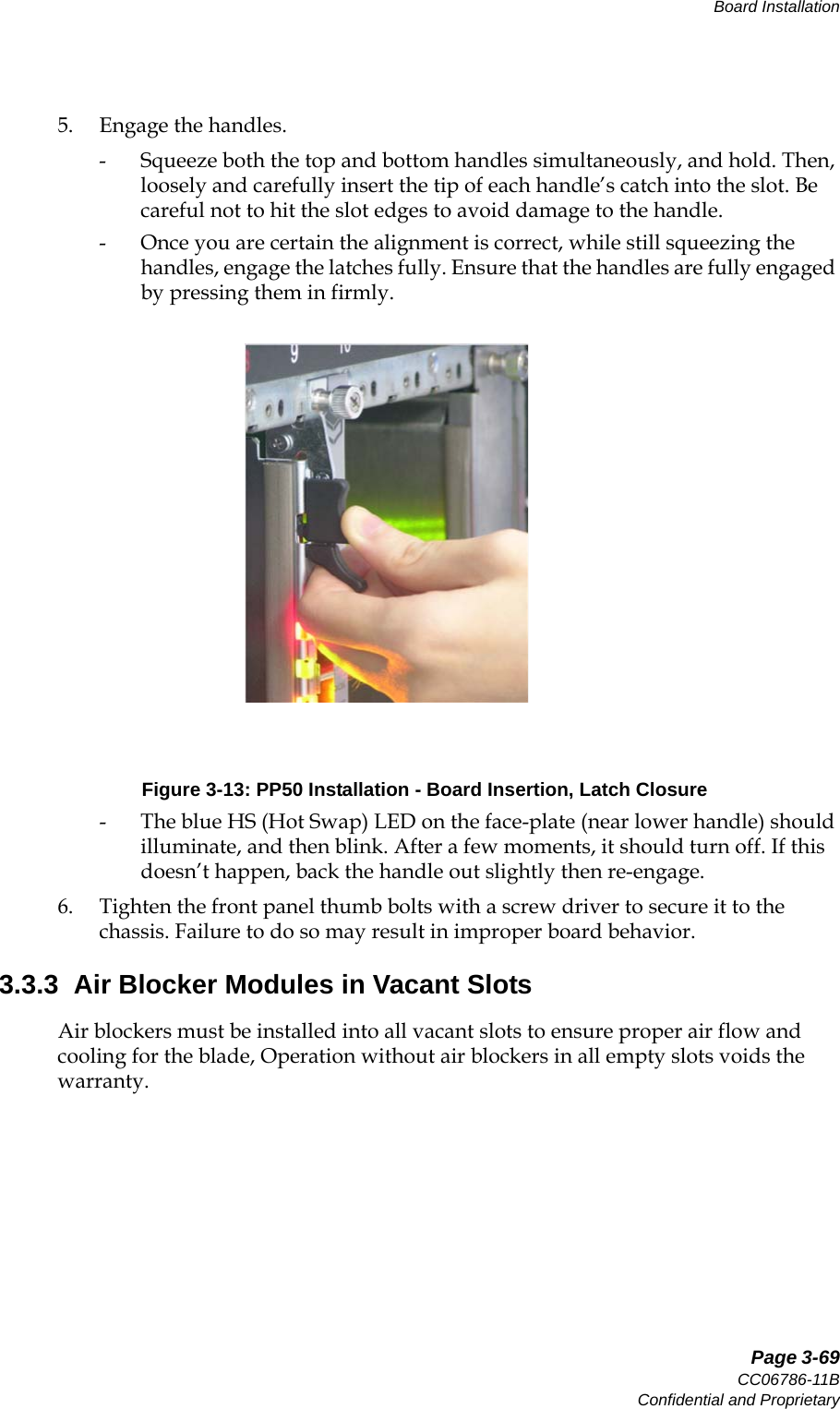

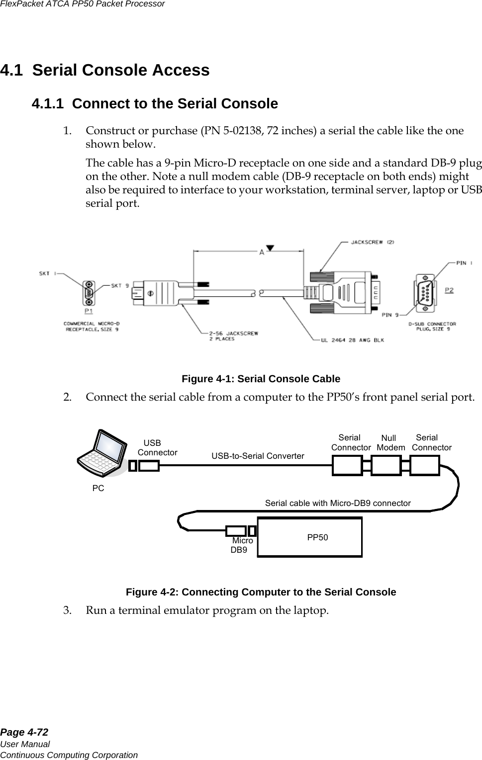
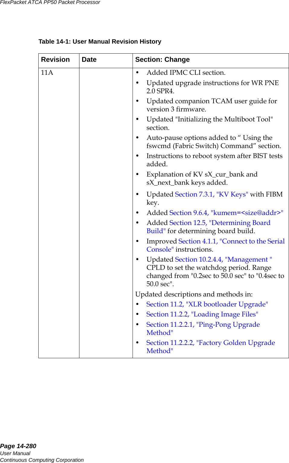
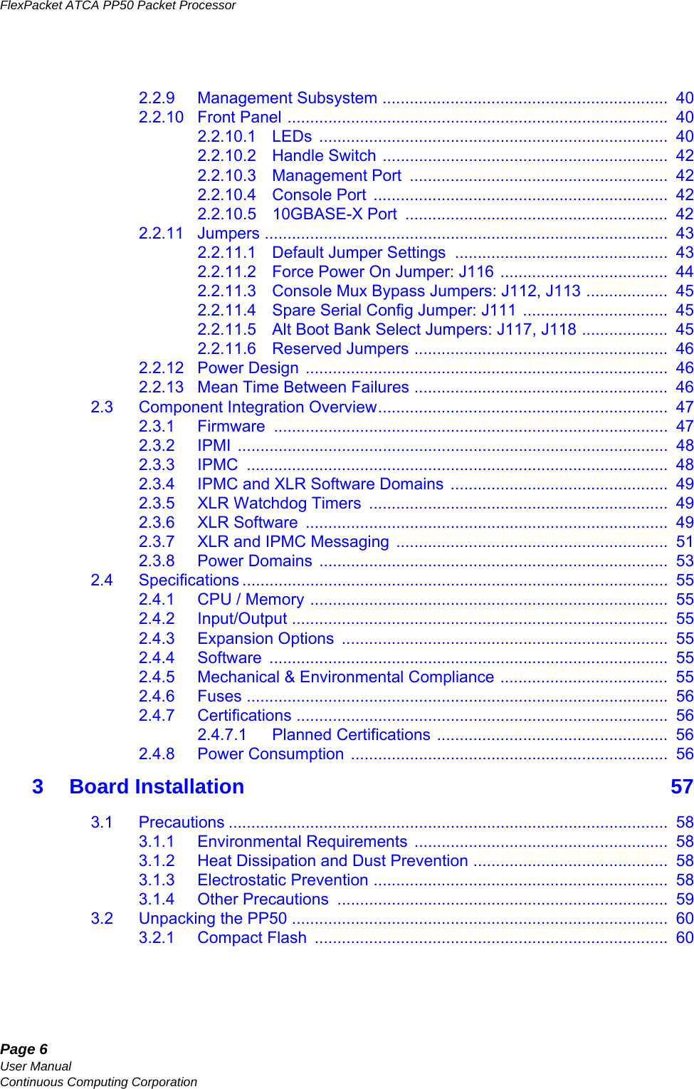
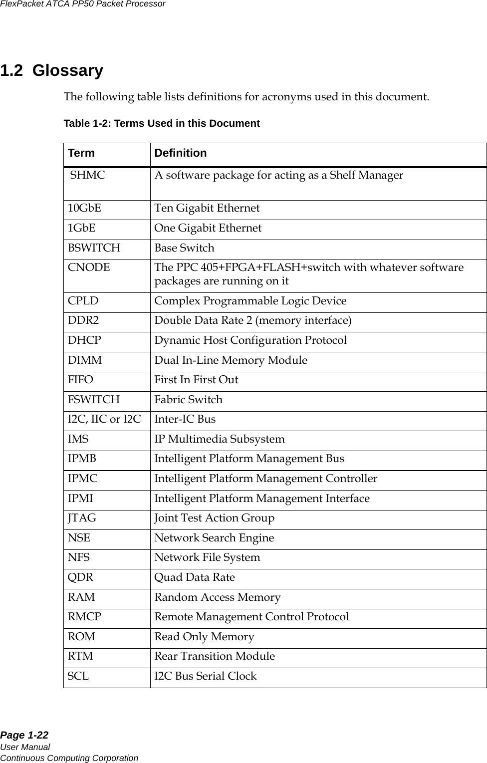
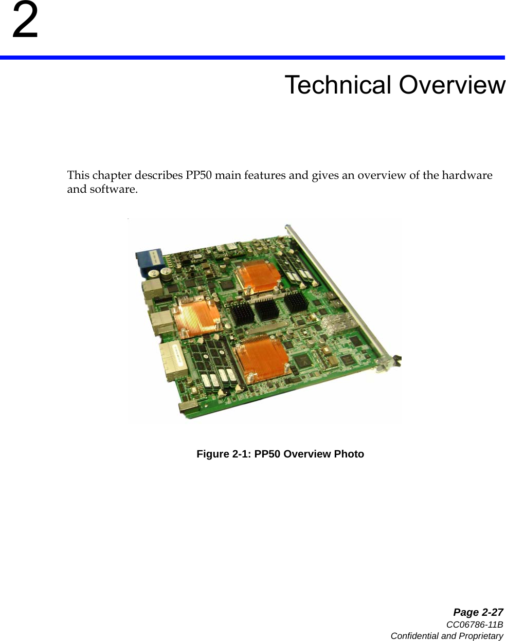
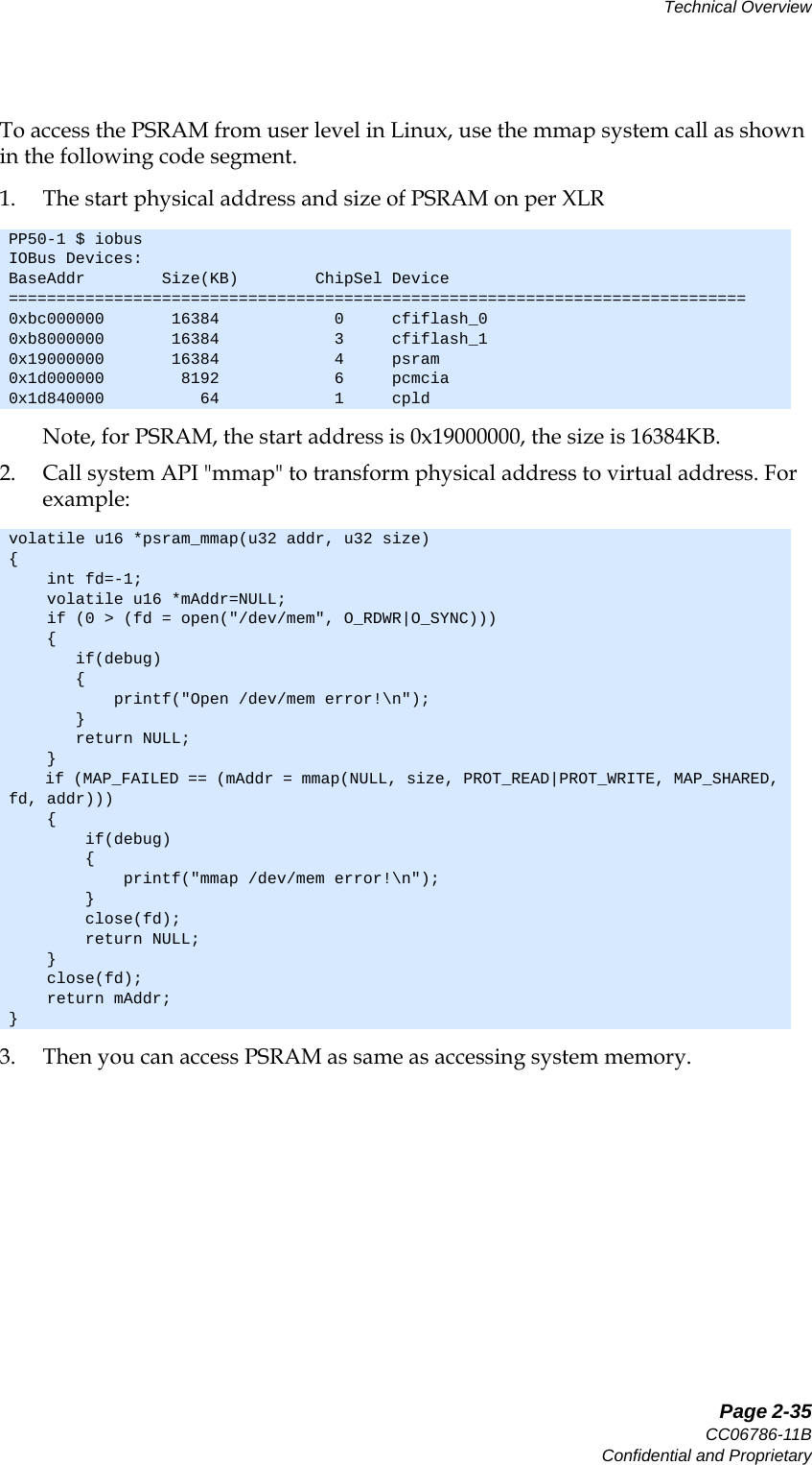
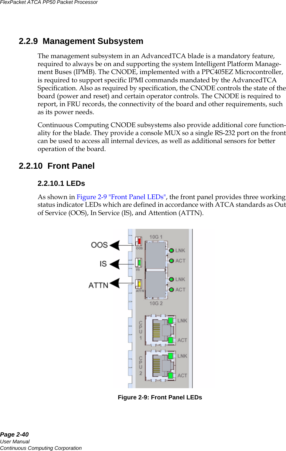
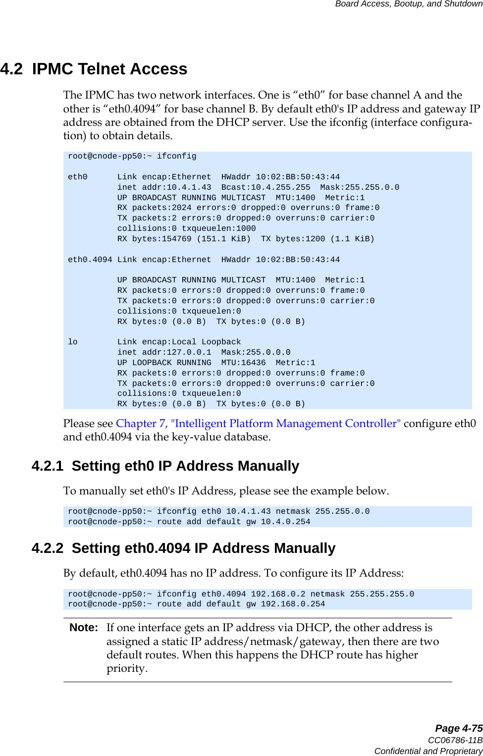
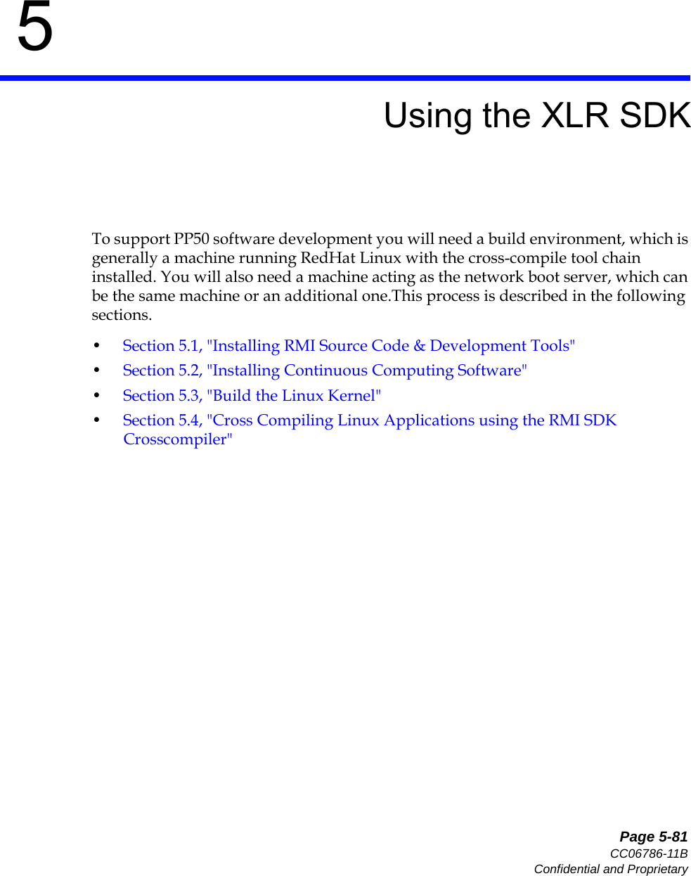
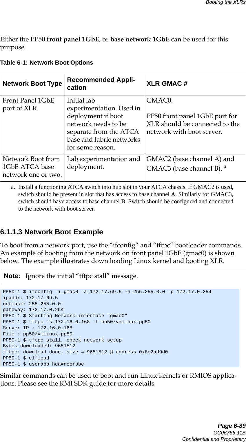
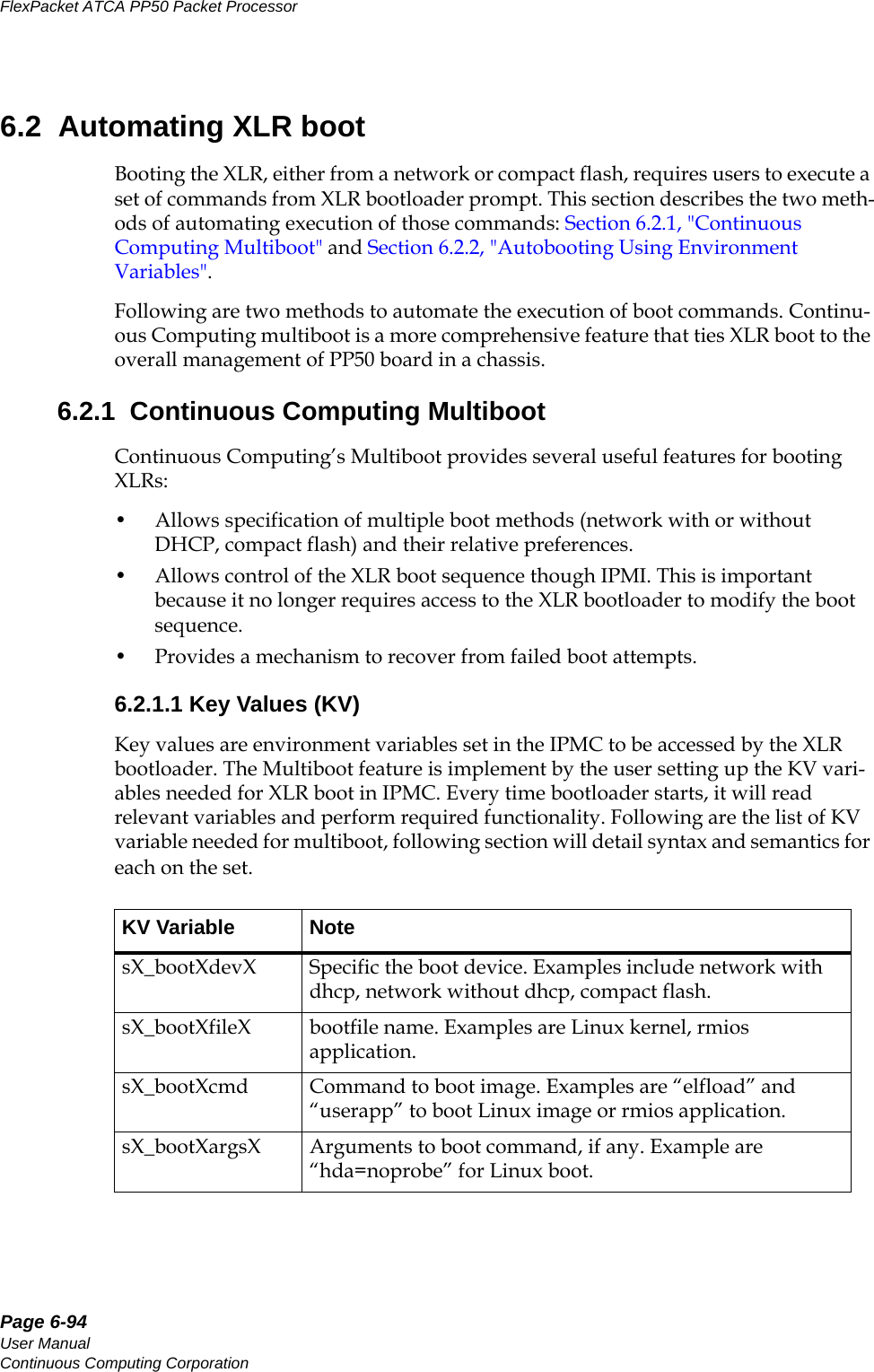
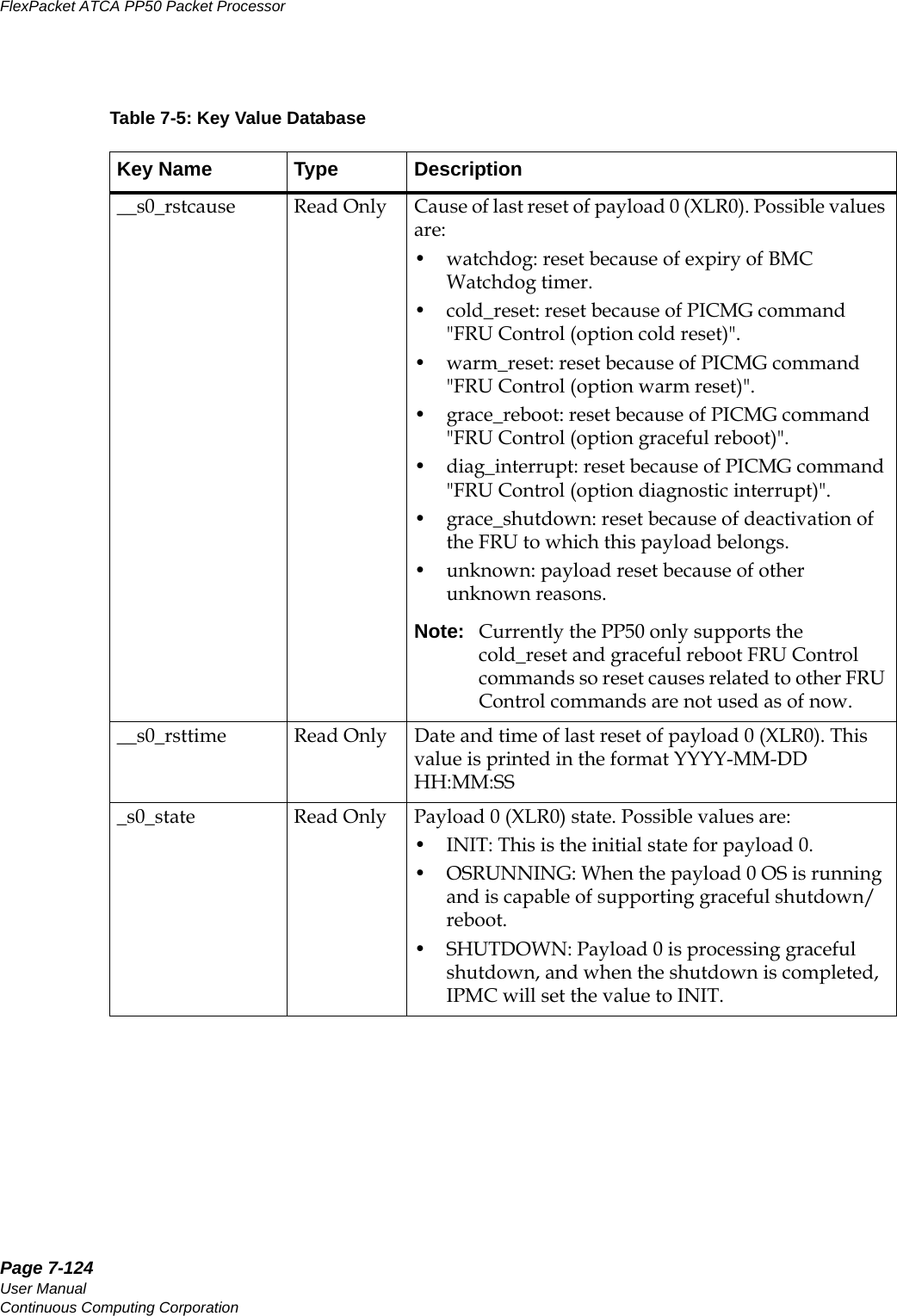
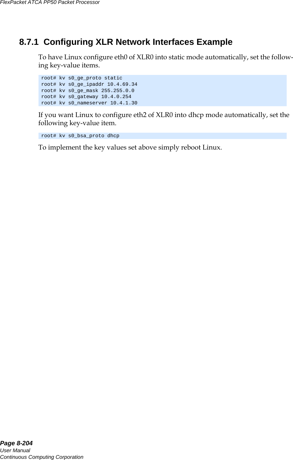
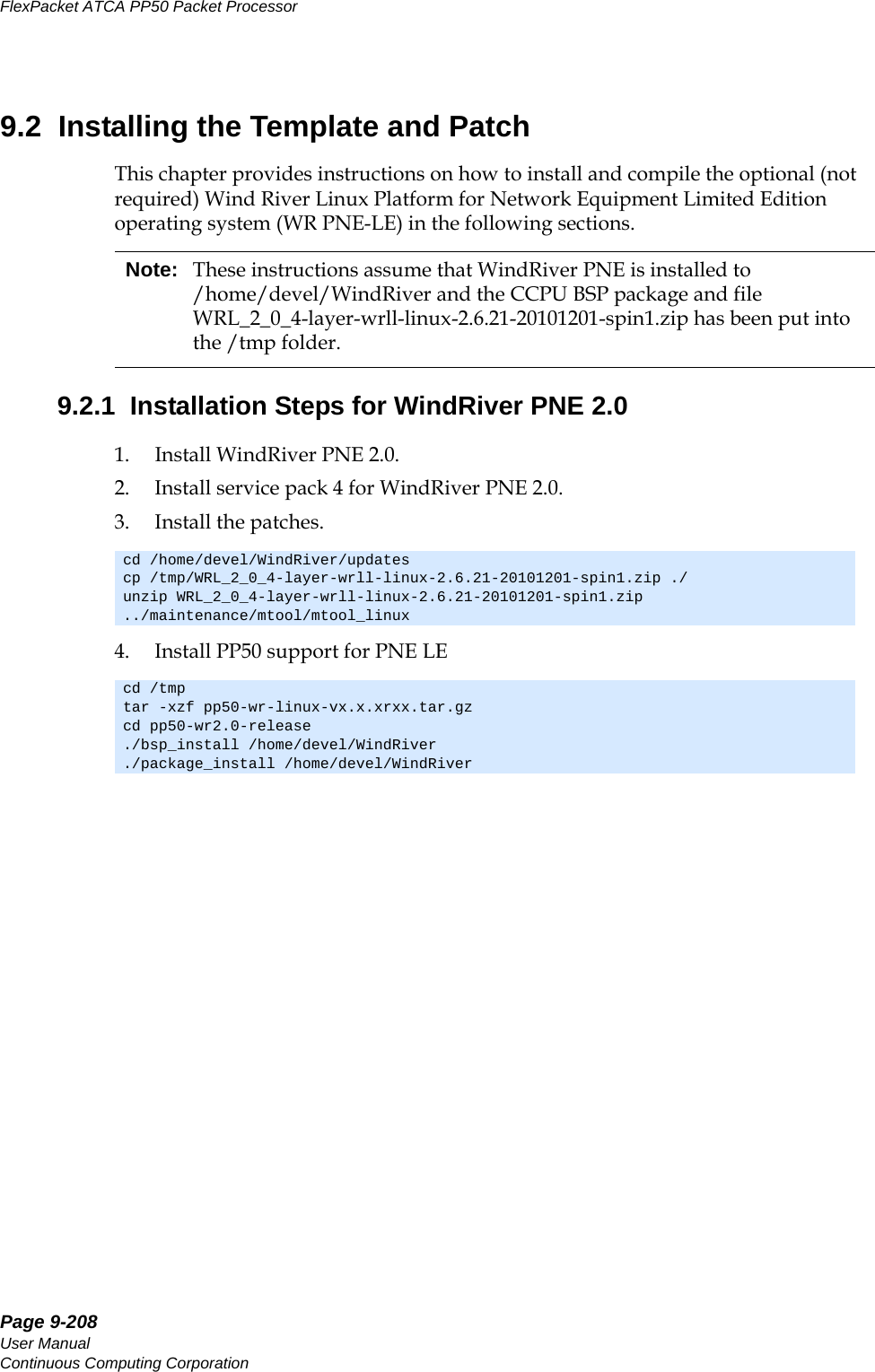
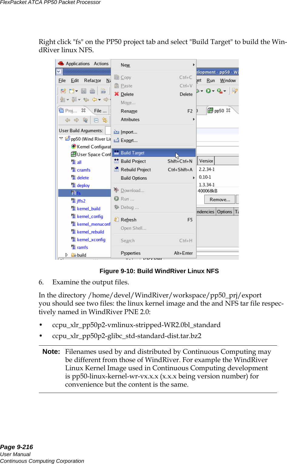
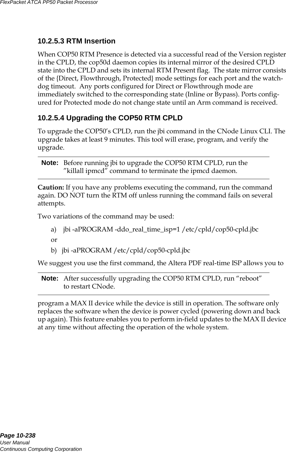
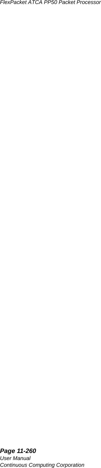
![Page 4-73CC06786-11BConfidential and ProprietaryBoard Access, Bootup, and Shutdown14ABABPreliminary4. Use the following connection settings:- 115200 baud rate-No parity-8 bits-1 stop bit- no flow control5. Boot the PP50. By default the console is the IPMC running Linux. 6. See the next section to toggle between the IPMC and XLRs.4.1.2 How to Switch Between Serial Consoles (IPMC, XLRs)Use the following sequences to switch the front panel console port between CPUs:On the front panel console, use the following sequences to connect to the XLR's serial console via the IPMC:• In the IPMC, use command "cu" to switch the console to XLR0• In IPMC Linux, use command "cu" to switch the console to XLR1• To disconnect from the XLR serial console, press “~”, and “.”.Note: During bootup, if the board receives any keystroke signals from the serial port, boot up will be halted. Incorrect connection settings can cause false signals so it is critical the parameters above are set correctly. cu -l /dev/ttyS2acu -l /dev/ttyS2bcu -l /dev/ttyS2ccu -s 38400 -l /dev/ttyS3 (secondary XLR0 console when running in dual mode Linux/RMIOS)cu -l /dev/ttyS4acu -l /dev/ttyS4bcu -l /dev/ttyS4ccu -s 38400 -l /dev/ttyS5 (secondary XLR1 console when running in dual mode Linux/RMIOS)Note: If you connect to the IPMC's console port by telnet or Windows Hyperterm, the telnet escape character is Ctrl-]. If you use a shell or program that uses “~” as its escape character (such as SSH or another CU session), then you must type two “~”s for each “~” that actually needs to get to the IPMC.](https://usermanual.wiki/UTStarcom/MSG2000/User-Guide-2403206-Page-71.png)

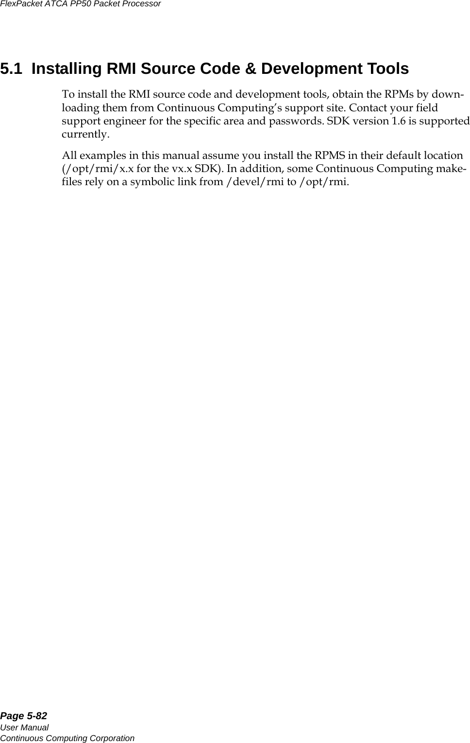
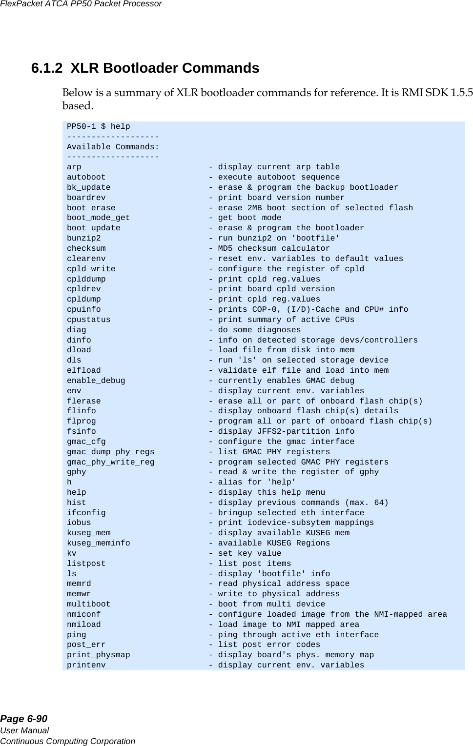
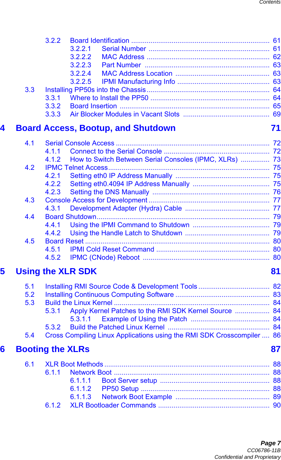
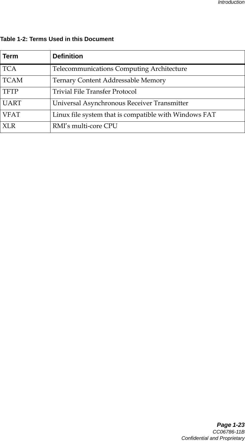
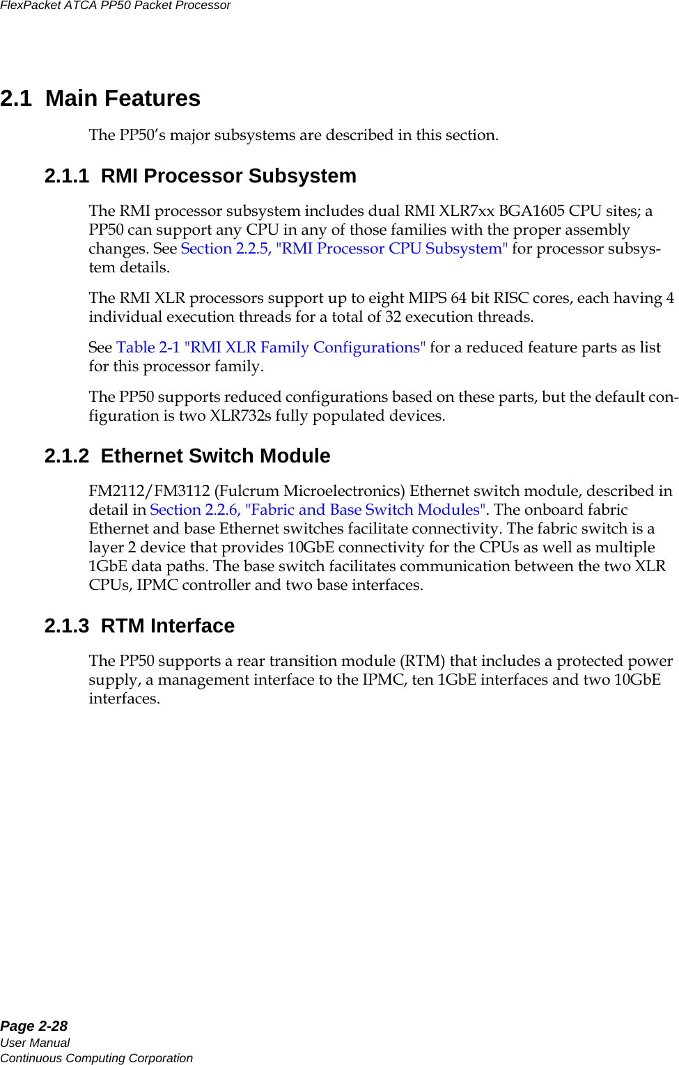
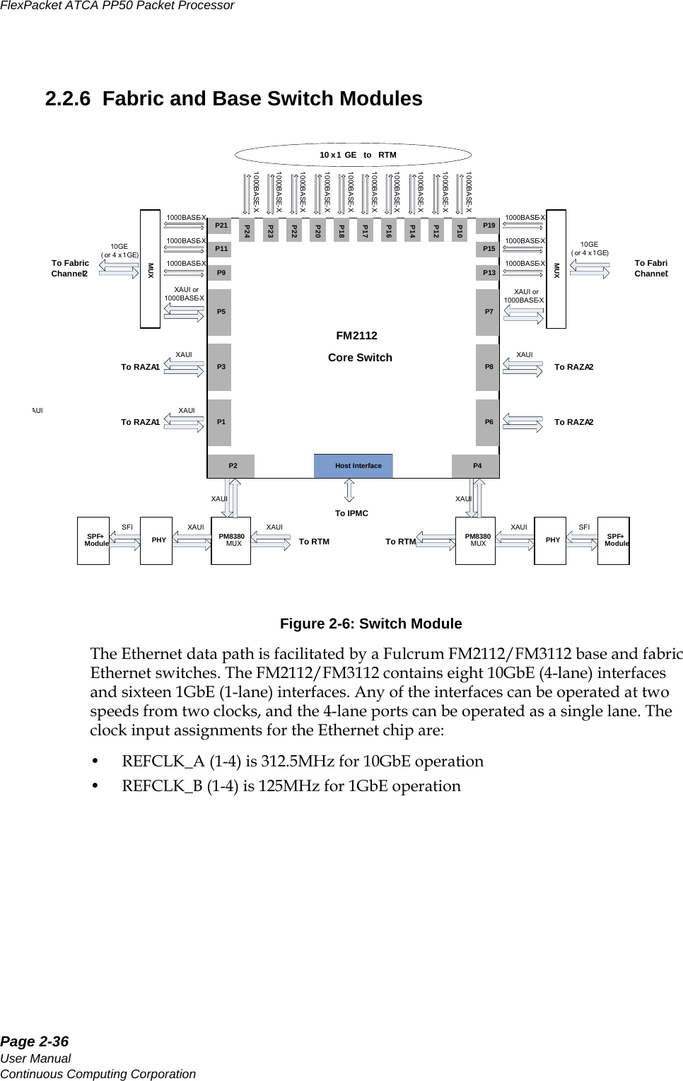
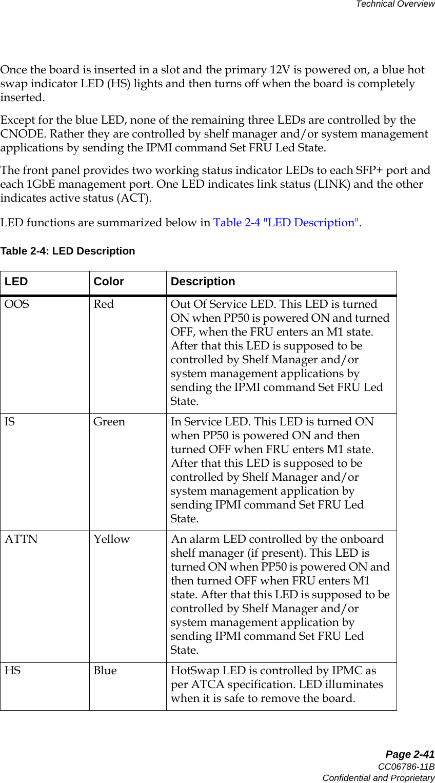
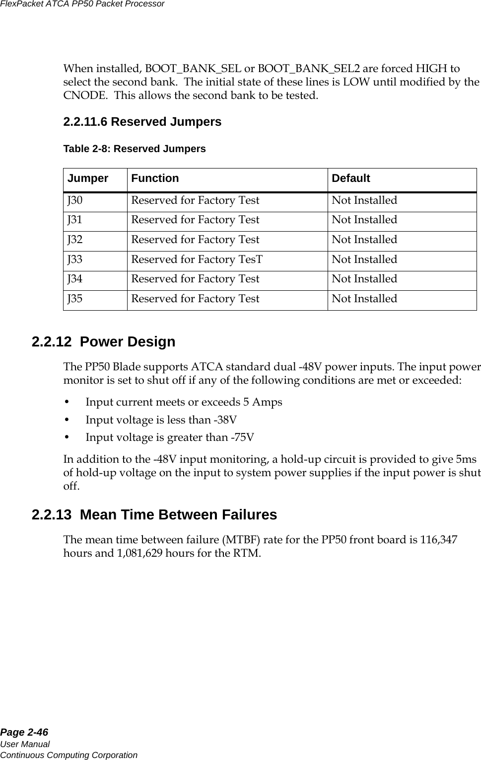
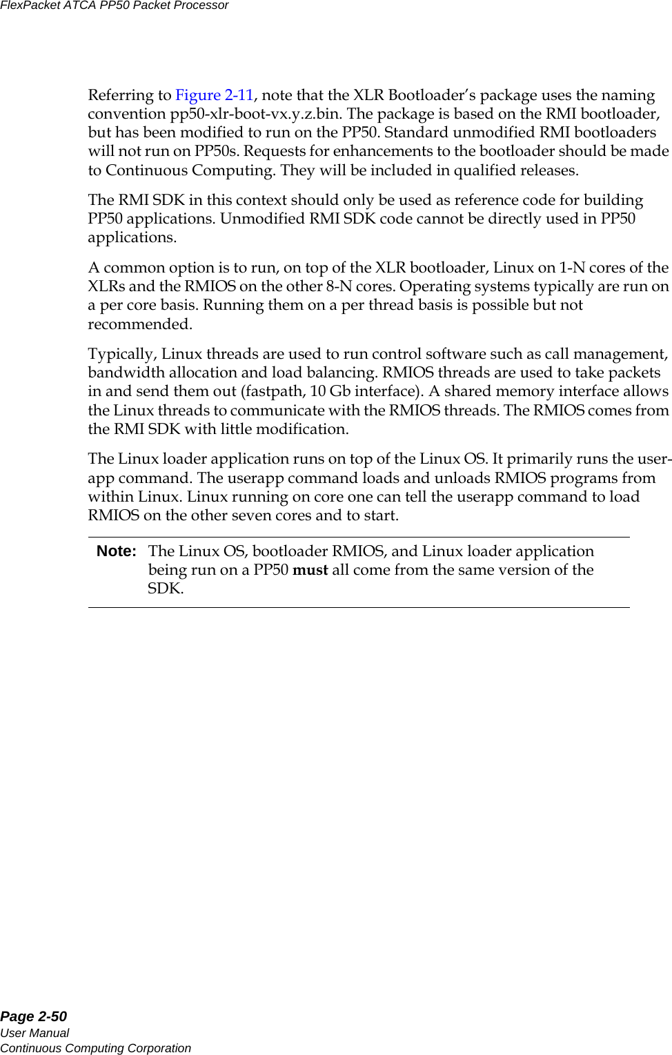
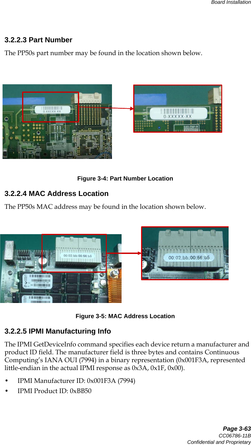
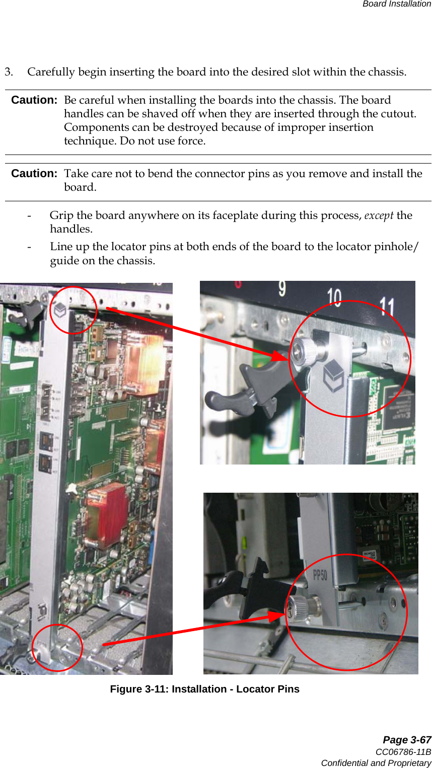
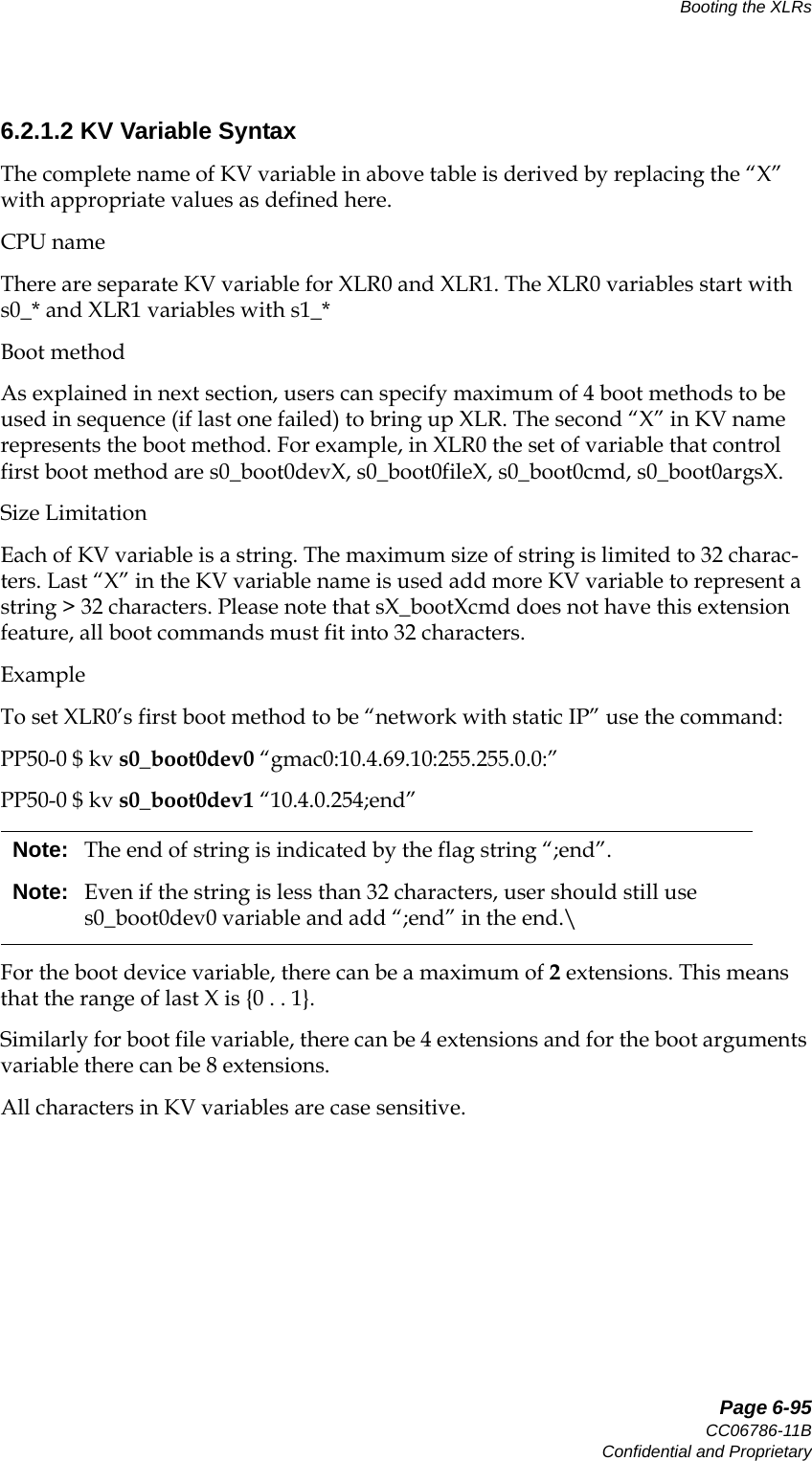
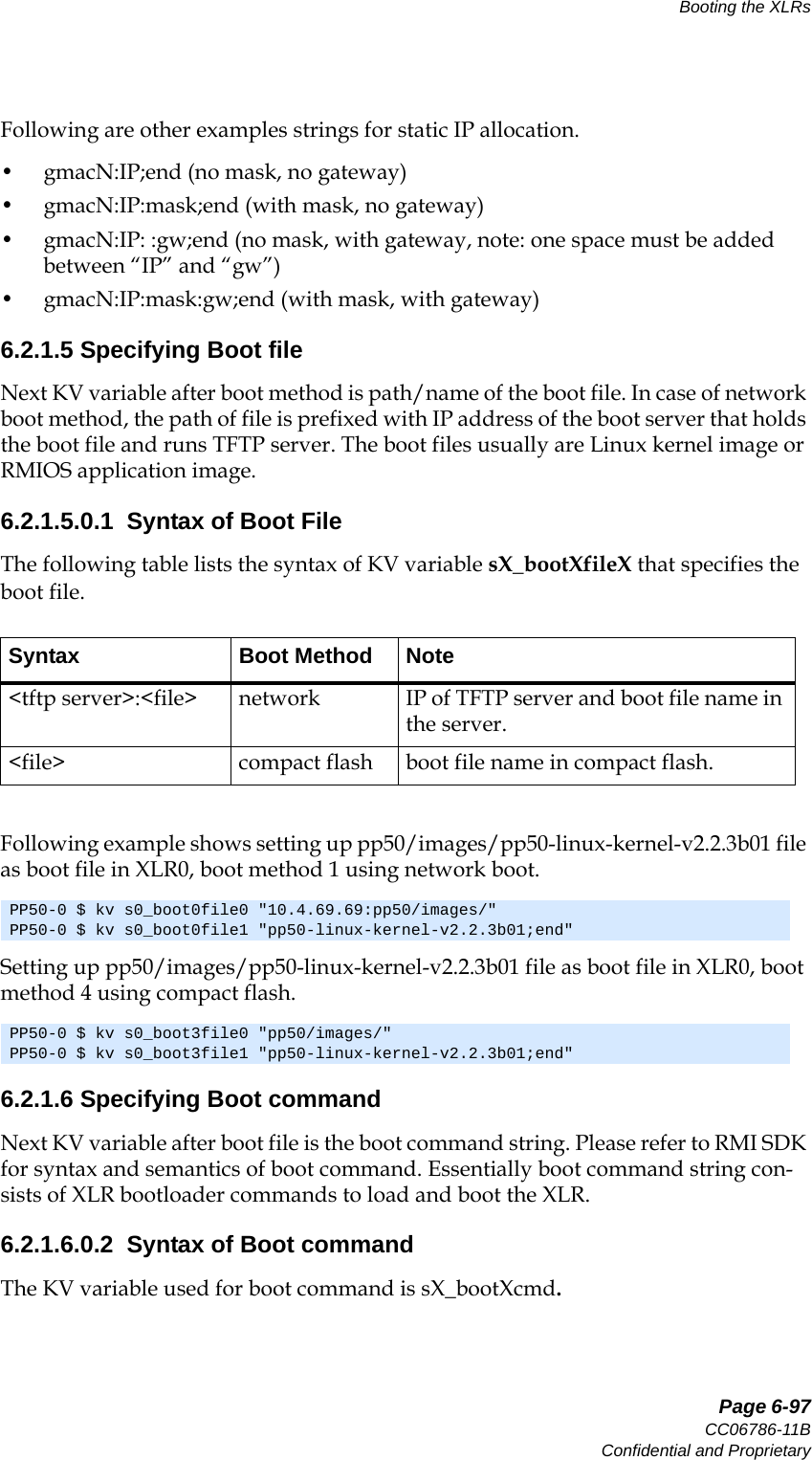
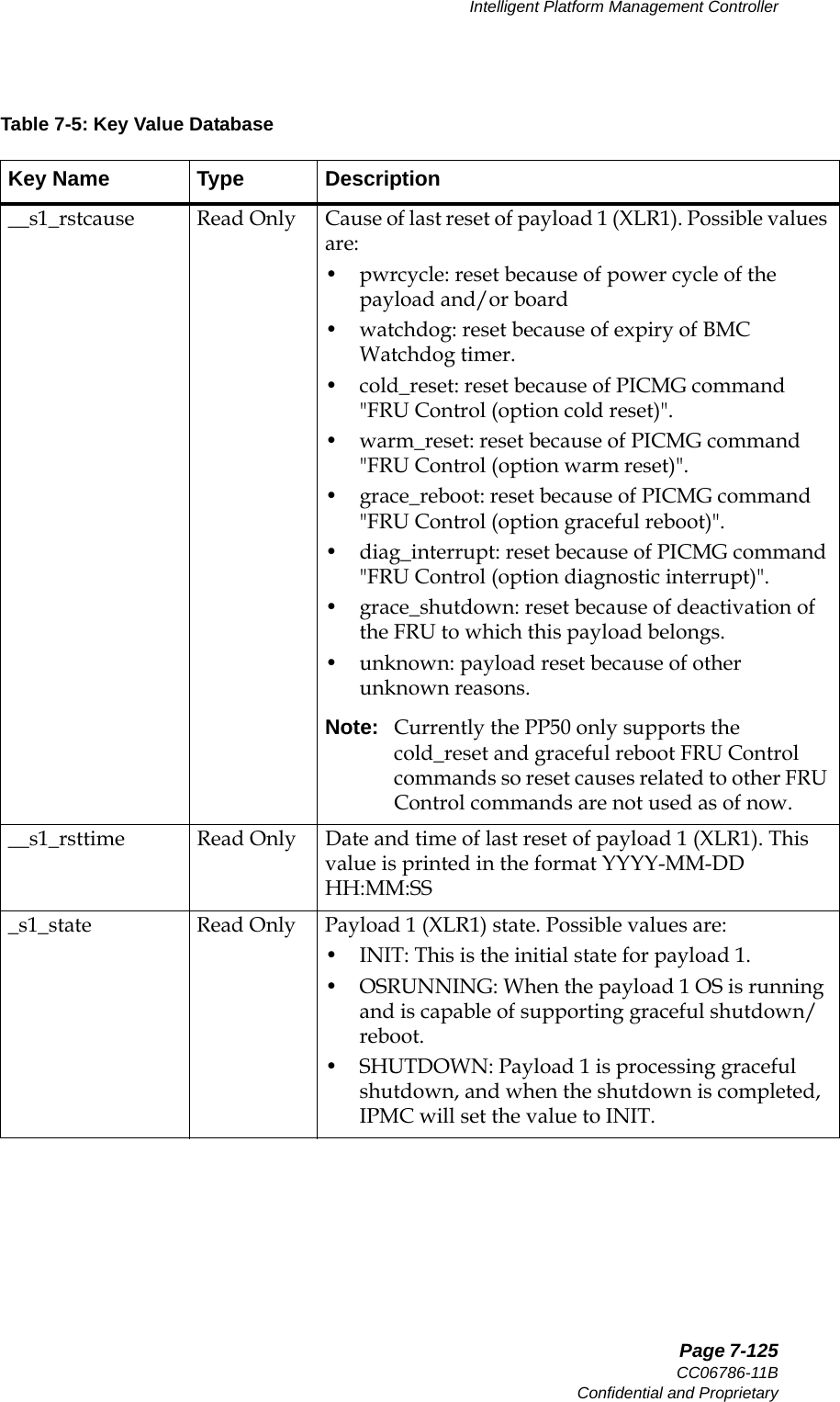
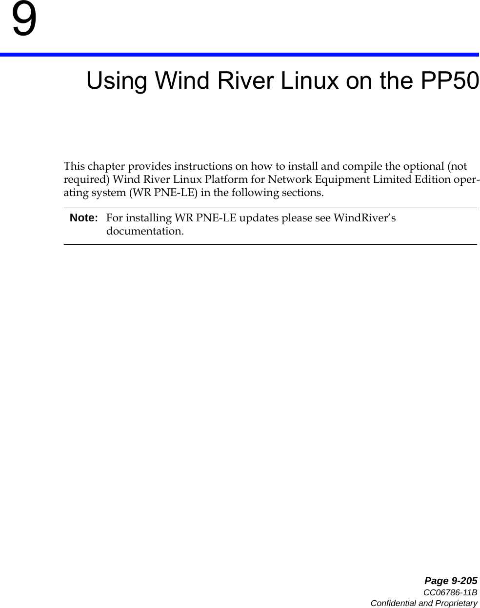
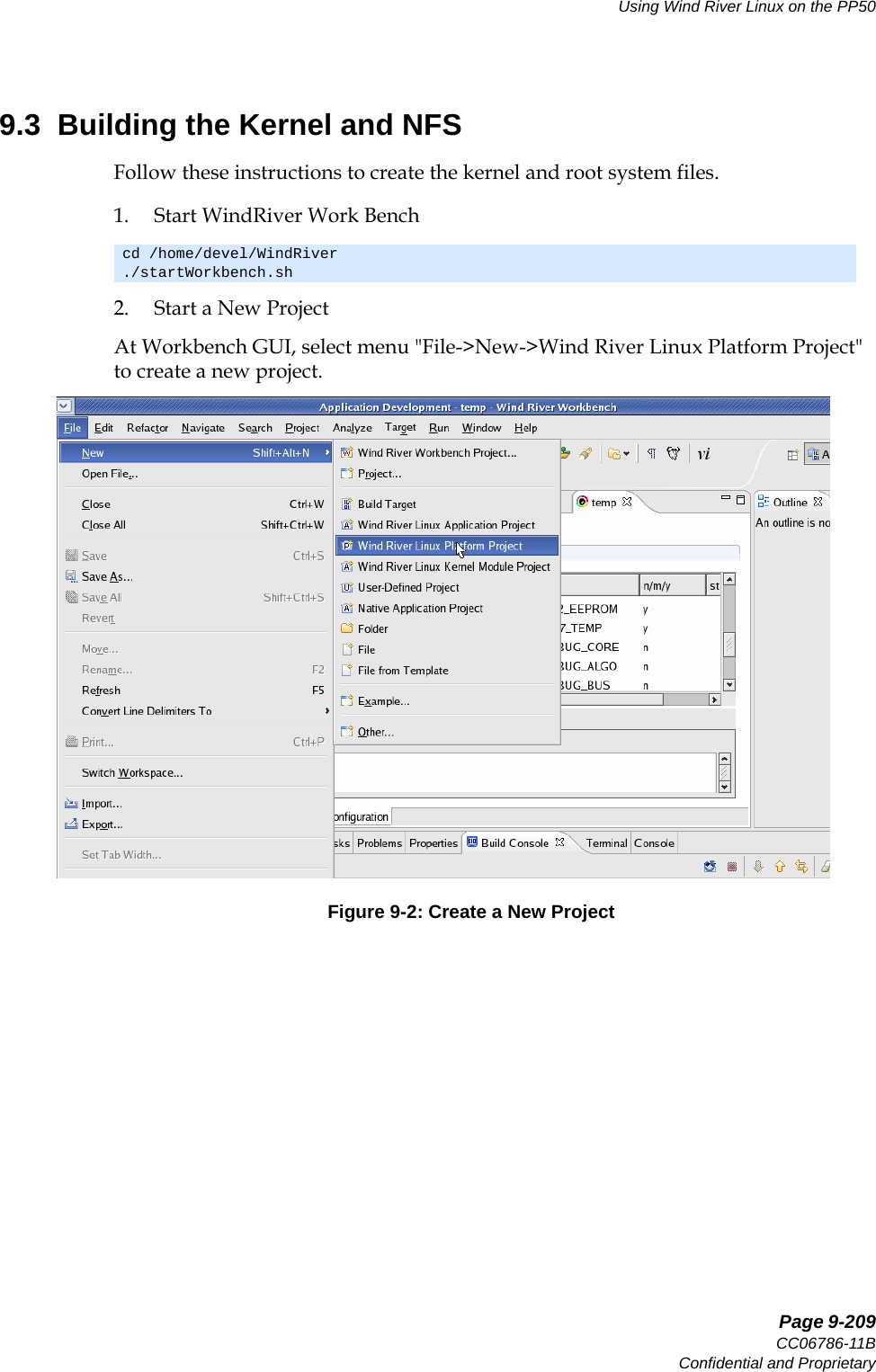
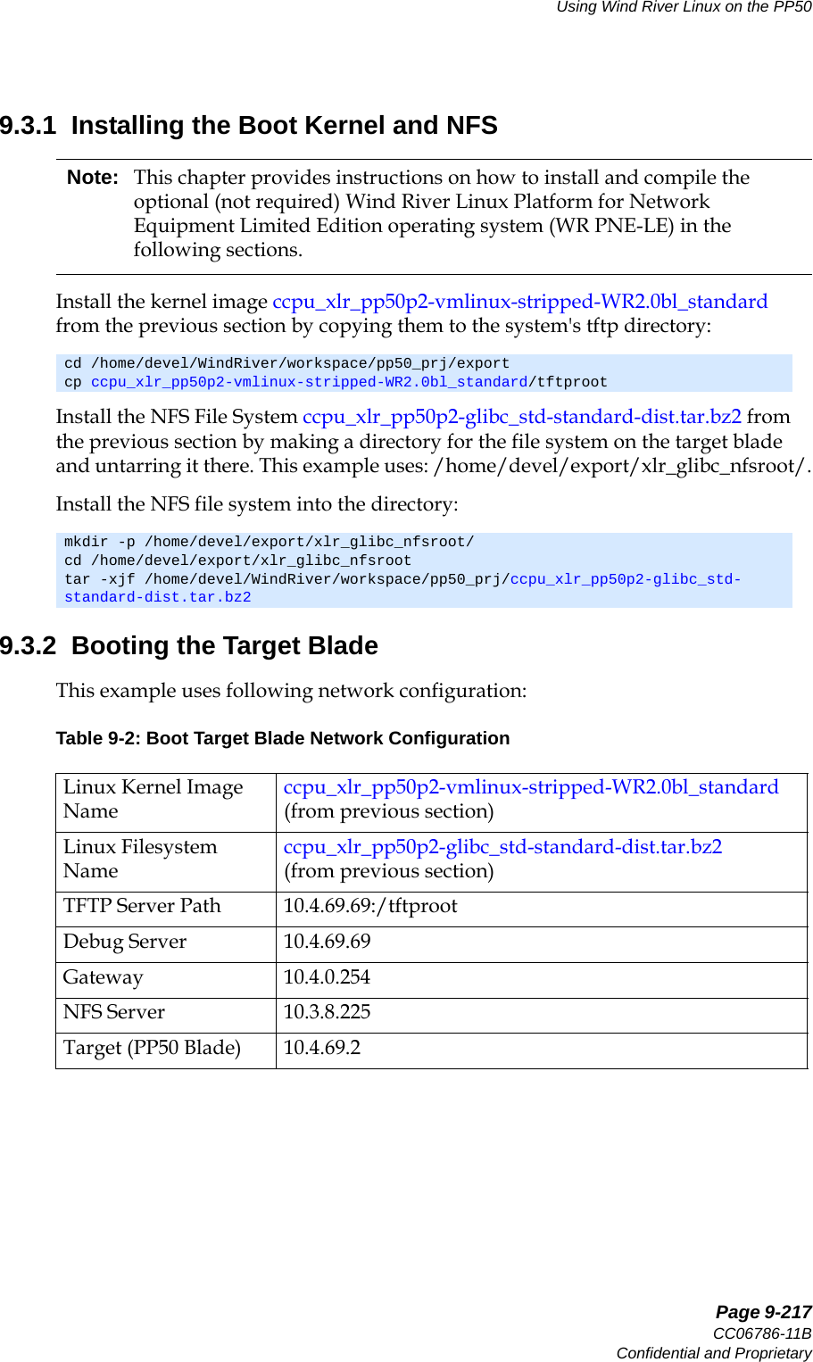
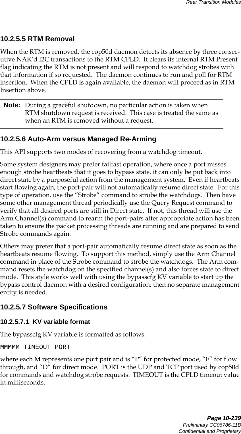
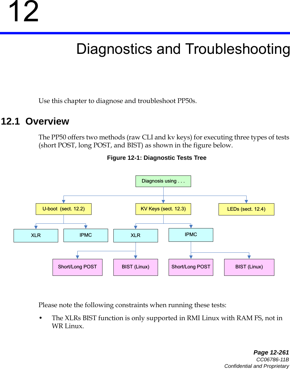
![Page 6-93CC06786-11BConfidential and ProprietaryBooting the XLRs14ABABPreliminary4. List CF card operation commands5. List the CF card files6. Load file vmlinux-p2-dbg03 to memory. If the CF is formatted to FAT run: If the CF is formatted to ext run: 7. Load the elf file8. Boot RMI LinuxPP50-1 $ dlsFilesystem Commandsdload <disk> <partition> <file> [bytes] - Load the specified number of [bytes] from <disk> <partition> <file> to memory. If [bytes] is omitted, then the value of bytes will be the size of file or 15MB, whichever is less.dls <disk> <partition> [directory] - list the files from <disk> <partition> [dir]PP50-1 $PP50-1 $ dls pcmcia_1 1Listing / directory. 0 thisiscompactflash 3139 testcmd.txt 9684280 vmlinux-p2-dbg03 3910938 vmlinux-wr054 file(s), 0 dir(s)PP50-1 $PP50-1 $ dload pcmcia_1 1 vmlinux-p2-dbg03PP50-1 $ dload pcmcia_1 1 /vmlinux-p2-dbg03PP50-1 $ elfloadPP50-1 $userapp hda=noprobe hdb=noprobe](https://usermanual.wiki/UTStarcom/MSG2000/User-Guide-2403206-Page-91.png)
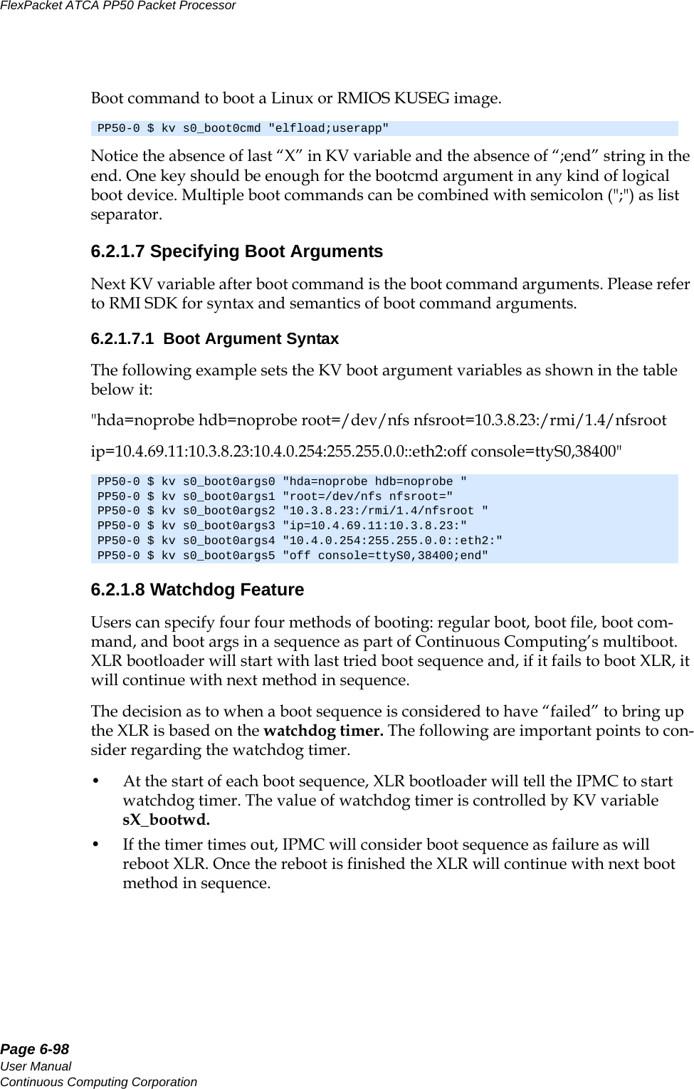
![Page 6-96User ManualContinuous Computing CorporationFlexPacket ATCA PP50 Packet Processor Preliminary6.2.1.3 Access to Multiple Boot MethodThe multiboot method allows users to specify multiple boot methods to be tried in a given sequence. For example, the user can set “network with dhcp” as the first option to boot XLR, “network with static IP” as second option in case DHCP server is down and so on. The bootloader will start with first method, if it fails to bring up the board it will try the next method and so on. The user can specify up to four such boot methods.The bootloader decides a boot method has failed based on the watchdog mechanism explained in Section6.2.1.8, "Watchdog Feature". If the watchdog timer expires, it will use the next boot method in sequence. 6.2.1.4 Boot Method SyntaxFollowing table lists the syntax of KV variable sX_bootXdevX that specifies the boot method.Since colon(':') is used in the syntax of string, it can't be used in directory or file name.For example, network boot using gmac2 and DHCP for second boot method in XLR1.Syntax Boot Source NotegmacN:IP[:mask][:gateway](static IP) Select the boot GMAC port and specify the static host IP address to be used.gmacN:dhcp_only (dynamic IP) Host IP address is requested from DHCP server.gmacN:dhcp_tftp (dynamic IP) Host IP address, gateway, TFTP server and boot file name are requested from DHCP server.Note that in this case user does not have to specify sX_bootXfileX variable.cflash:partition (CF card boot) CF card as boot device, the partition field is the partition number.PP50-1 $ kv s1_boot1dev0 “gmac2:dhcp_only;end”](https://usermanual.wiki/UTStarcom/MSG2000/User-Guide-2403206-Page-94.png)
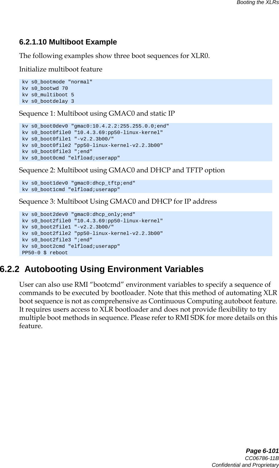
![Page 6-99CC06786-11BConfidential and ProprietaryBooting the XLRs14ABABPreliminary• If the boot method is successful, it is the responsibility of booted entity to stop the watchdog timer in IPMC. Failure to do so will result in IPMC rebooting XLR. Currently, if XLR is booted to Linux, user can add a utility called “ipmi_setwd” as part of their root file system. Calling this utility, preferably from init scripts, will reset the watchdog timer in IPMC. Currently, there is no such utility available for RMIOS application. • The watchdog feature can be disabled by setting value of sX_bootwd to 0. In this case user have to manually reboot XLR to continue with next boot sequence.It is important to set the right value for watchdog timer. The value should ideally be largest of the time it take to boot XLR for each sequence. Given that booting Linux takes most time, the timer value can be set based of Linux boot time. Typically it takes about 60 seconds to boot the RMI Linux or WindRiver Linux kernel on PP50, so 70 is a good value to start with.Example of setting watchdog timer.To find which payload stage's watchdog timer expired run the following command:6.2.1.8.2 Stopping Watchdog Timer in LinuxAs noted above after a successful boot, the watchdog timer must be stopped. Linux provides the “ipmi_setwd” utility which can perform this operation (present in Util-ities directory in release). For booting RMI linux kernel from its own RAM FS• The binary of RMI Linux kernel with version later than "v2.2.3b00" has included this utility as part of ramdisk.• For kernel version less that "v2.2.3b00" user has to rebuild kernel and add this utility as part of initramfs. For booting linux from nfsroot you need to add “ipmi_setwd” in /usr/bin of the nfsroot and set it as executable using the "chmod a+x ipmi_setwd" command.You must also add following line in the nfsroot script file /etc/inittab, 6.2.1.9 Initializing MultibootMultiboot is initialized by setting kv entries as described below.6.2.1.9.3 Setting the s[0_1]_multiboot Key ValueSpecify the way of XLR multiboot/autoboot through setting the s[0|1]_multiboot KV key.PP50-0 $ kv s0_bootwd "70" cat /var/log/messages | grep expired0:12345:once:/usr/bin/ipmi_setwd 0](https://usermanual.wiki/UTStarcom/MSG2000/User-Guide-2403206-Page-97.png)
![Page 6-100User ManualContinuous Computing CorporationFlexPacket ATCA PP50 Packet Processor PreliminaryKV key s[0|1]_multiboot = 1 - Try to boot from KV key boot0dev (similar to "multiboot -s 0")2 - Try to boot from KV key boot1dev (similar to "multiboot -s 1")3 - Try to boot from KV key boot2dev (similar to "multiboot -s 2")4 - Try to boot from KV key boot3dev (similar to "multiboot -s 3")5 - Try to boot from KV keys boot0dev through boot3dev (similar to "multiboot -s a") 10 - Try to boot using the XLR's environment variables - bootcmd0 through bootcmd920 - Do not auto boot, force to bootloader prompt regardless of environment vari-ables and Key-Value settingsUnsupported value - Display this usage information and force to bootloader prompt6.2.1.9.3.1 Setting the s[0|1]_bootdelay Key ValueSpecify the waiting time before starting multiboot/autoboot through setting the KV key s[0|1]_bootdelay.s[0|1]_bootdelay = 0 - boot with no waiting < 0 - do not boot and force to bootloader prompt > 0 - start to boot after the set time (seconds)Note: If KV key s[0|1]_multiboot is not set or deleted, XLR will auto boot using the environment variables (bootdelay, bootcmd0 through bootcmd9), which is as same as chapter 6.2.2 said.Note: If the kv key s[0|1]_bootdelay is not set or deleted, it will be handled as if the default value '-1' was set and will force the bootloader prompt. Note: If the kv key s[0|1]_bootdelay is set to a wrong value by mistake, it will boot with no waiting.](https://usermanual.wiki/UTStarcom/MSG2000/User-Guide-2403206-Page-98.png)
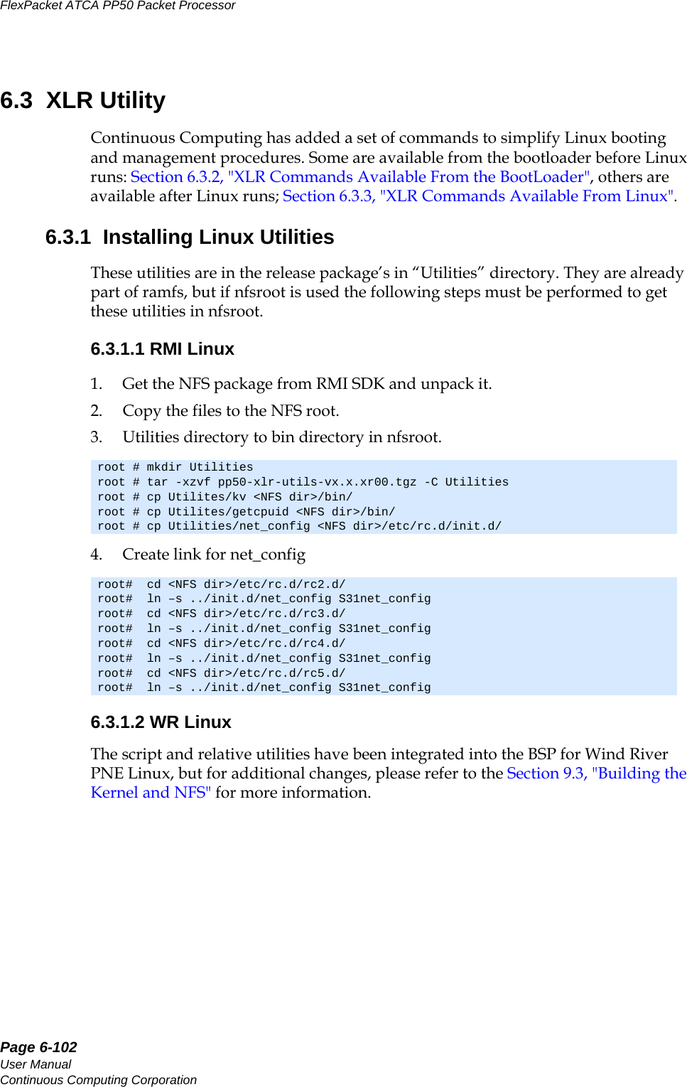
![Page 6-103CC06786-11BConfidential and ProprietaryBooting the XLRs14ABABPreliminary6.3.2 XLR Commands Available From the BootLoaderThe commands in this section are included in the XLR and IPMC firmware and are used to boot the XLR. 6.3.2.1 kvSets a key value in the database. See Section7.4, "Key Value (KV) Database" for details.Detail DescriptionSynopsis kv [key [value]]Options -k prints entries in shell-compatible syntax.-V display version of kv utility.-h display command usage.-d delete a key from database. Examples xlr prompt] kv ipmc_version = "pp50-ipmc-v2.4.3r00" datetime = "2009-04-29 23:20:42" epochtime = "1241047243" xlr0base = "00:02:BB:50:32:90" xlr1base = "00:02:BB:50:32:98" pyld0_compat = "8.2" pyld1_compat = "8.2" hwaddr = "43" f1_presence = "1" f2_presence = "0" __pwr_regs = "ff00000000000000" __f0_poh = "770" __s0_rstcause = "cold_reset" __s0_rsttime = "2009-04-29 23:07:31" __s1_rstcause = "cold_reset"[xlr prompt] kv -Vkv version 1.1[xlr prompt] kv hello there[xlr prompt] kv hello hello = "there"[xlr prompt] kv -d hello[xlr prompt] kv helloKey 'hello' not found](https://usermanual.wiki/UTStarcom/MSG2000/User-Guide-2403206-Page-101.png)
![Page 6-104User ManualContinuous Computing CorporationFlexPacket ATCA PP50 Packet Processor Preliminary6.3.2.2 showbootShows the bank where the bootloader booted from (xlr active flash bank id).6.3.2.3 rollbootSwitches to the other flash bank and boots.6.3.3 XLR Commands Available From LinuxThe following commands are available after the XLR has booted WR/RMI Linux.6.3.3.1 NTP clientThe Network Time Protocol (NTP) daemon synchronizes RMI Linux time with NTP servers. Please refer to README file in NTP directory of Utilities package for more on installation.6.3.3.2 kv See Section6.3.2.1, "kv" for details.6.3.3.3 showbootSee Section6.3.2.2, "showboot" for details.Detail DescriptionSynopsis showbootOptions no optionsExamples [xlr prompt] showbootSystem was booted from bank 0.The active bank version is: v2.5.0r00Detail DescriptionSynopsis rollbootOptions noneExample [xlr prompt] rollbootSystem was booted from bank 0.The active bank version is: v2.5.0r00Rollboot to bank 1...](https://usermanual.wiki/UTStarcom/MSG2000/User-Guide-2403206-Page-102.png)
![Page 6-105CC06786-11BConfidential and ProprietaryBooting the XLRs14ABABPreliminary6.3.3.4 rollbootSee Section6.3.2.3, "rollboot" for details.6.3.3.5 ipmi_setwdIPMI Set WatchDog timer, reboots the XLR based on the time specified; supports XLR multiboot feature. For details about its usage also see Section6.2.1.8, "Watch-dog Feature".6.3.3.6 fswcmdFabric Switch Command, provides fabric switch operation from the XLR side. See Section8.2.1, "Managing the Fabric Switch with fswcmd" for details. 6.3.3.6.1 fswcmd.cfg Configuration FileA small configuration file named fswcmd.cfg included in the release package pro-vides the address for the IPMC to ensure it can be accessed; for example, if the accessible IPMC interface IP address is 10.4.1.10, the following line should be in the fswcmd.cfg This config file indicates where the fabric switch daemon 'fswd' is. This file is required only when the fswcmd is executed on the XLR (RMI Linux or WindRiver Linux). Note this is not be confused with the fswitchCfg.def file and its associated kv key fswitchCfg. See Section8.2, "Fabric Switch Management" and Section8.2.2, "fswcmd Start Up File" for more details.Detail DescriptionSynopsis ipmi_setwd [-hv][seconds]Options -h help-v display versionseconds(decimal) = 0 stops the watchdog timerseconds(decimal) > 0 starts the watchdog timerExamples [xlr prompt] ipmi_setwd 22ip_address 10.4.1.10](https://usermanual.wiki/UTStarcom/MSG2000/User-Guide-2403206-Page-103.png)
![Page 6-106User ManualContinuous Computing CorporationFlexPacket ATCA PP50 Packet Processor Preliminary6.3.3.7 upgradeFor upgrading the xlr flash bank6.3.3.8 bswcmdThe bswcmd command provides base switch operation and information. See Sec-tion8.6, "CNode Base Switch (bswcmd) Command" for more information about this command.6.3.3.9 getcpuidReturns the XLR CPU ID of the XLR you are currently using.Detail DescriptionSynopsis upgrade <-a | -s> [options]Options ? Display this usage-V Display version of this program-a Use active flash for operation-s Use backup flash for operation-b <backup file> Backup flash info to a file-p <program file> Program file to flash-v <program file> Verify flash info with a fileExamples To backup:[xlr prompt] ./upgrade -a -b bootloader.bckTo program: [xlr prompt] ./upgrade -s -p bootloader.binTo verify: [xlr prompt] ./upgrade -s -v bootloader.binDetail DescriptionSynopsis getcpuidOptions NoneExamples [root@localhost xlr-utils]$ ./getcpuidxlr cpu id is: 0](https://usermanual.wiki/UTStarcom/MSG2000/User-Guide-2403206-Page-104.png)
![Page 6-107CC06786-11BConfidential and ProprietaryBooting the XLRs14ABABPreliminary6.3.3.10 net_configConfigures the network interface using the KV keys in the database. It replaces setkv. 6.3.3.11 ipmi_setwdSets watchdog for supporting the XLR multiboot feature.Usage: ipmi_setwd [-hv][seconds] where: -h help -v display version seconds(decimal) = 0 stops the watchdog timer seconds(decimal) > 0 starts the watchdog timerDetail DescriptionSynopsis net_config {start|stop|restart|reload|status}Options {start|stop|restart|reload|status}Examples [xlr prompt] ./net_config stop[xlr prompt] ./net_config restart[xlr prompt] ./net_config reload[xlr prompt] ./net_config startAuto configure network from kv database... [ OK ][xlr prompt] ./net_config status](https://usermanual.wiki/UTStarcom/MSG2000/User-Guide-2403206-Page-105.png)
![Page 6-108User ManualContinuous Computing CorporationFlexPacket ATCA PP50 Packet Processor Preliminary6.3.3.12 ux_diagDiagnostic management utility based on kv schema.Usage: [Linux Prompt]$ ./ux_diag -h usage: ux_diag [-u|--update] [cn|s0|s1] usage: ux_diag [-l|--list] [cn|s0|s1] usage: ux_diag [-d|--dump] [cn|s0|s1] usage: ux_diag [-n|--no] [cn|s0|s1] usage: ux_diag [-h] -u update diagnosis configuration using /etc/diag/XX_diag.cfg -l list all available test items and test states configuration -d dump the test result and create /var/log/XX_diag.dump -n list current diagnosis test error number and err string -h for help](https://usermanual.wiki/UTStarcom/MSG2000/User-Guide-2403206-Page-106.png)
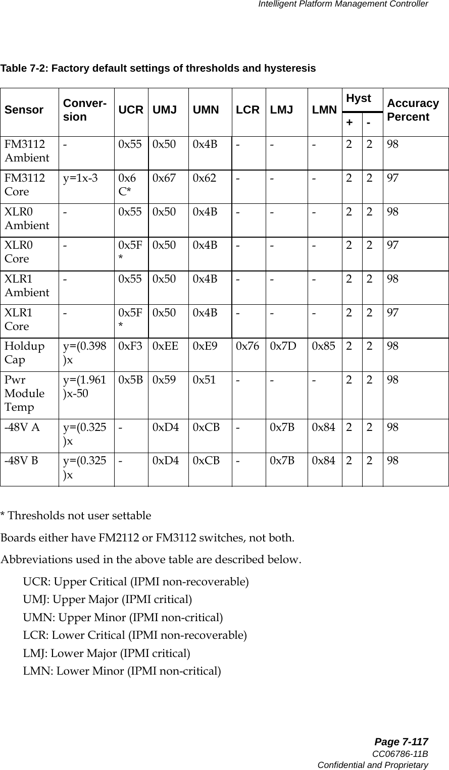
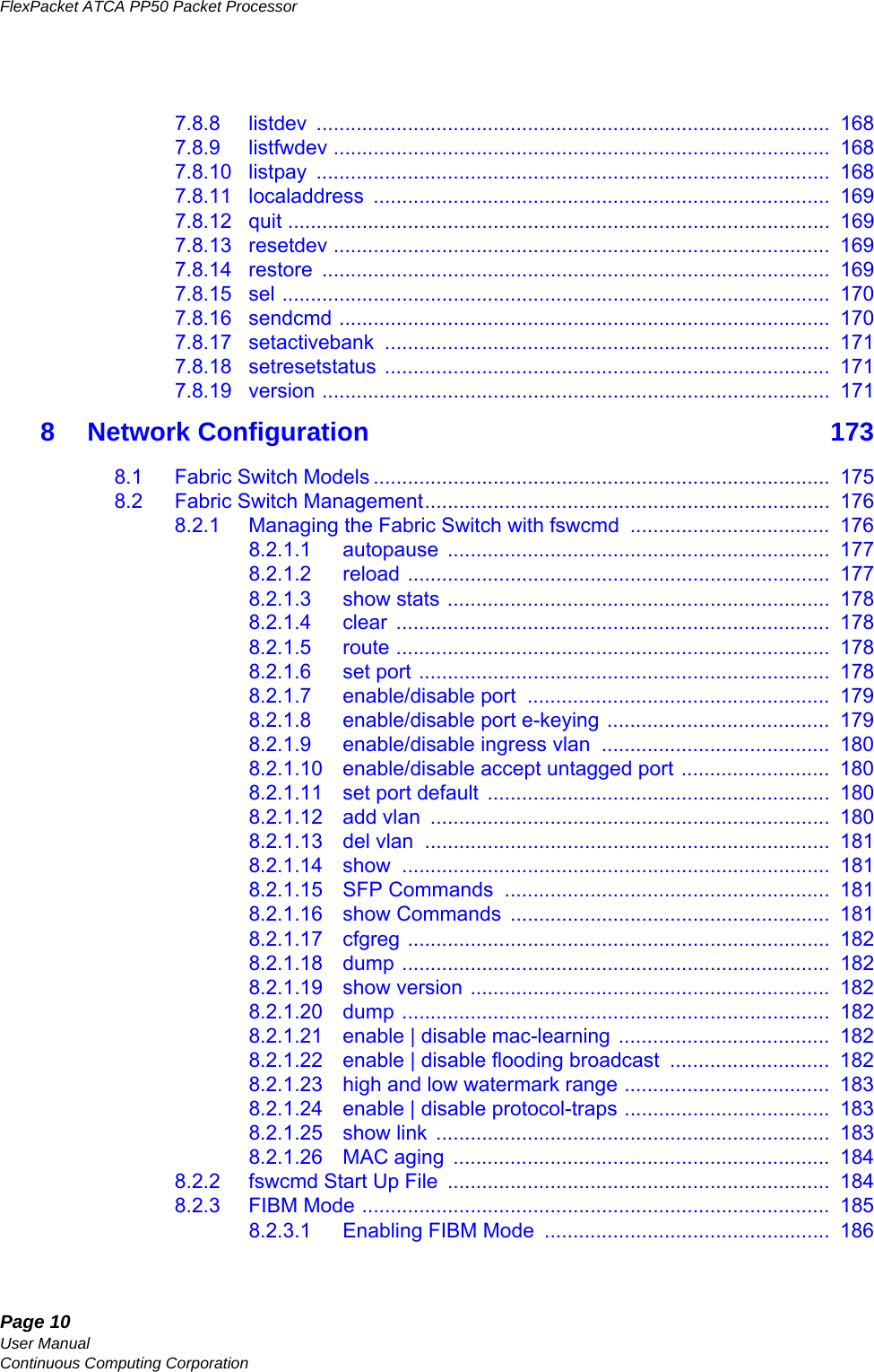
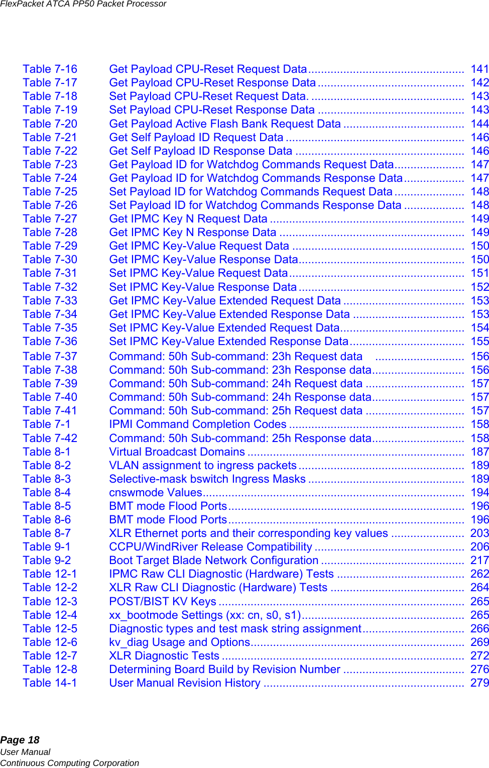
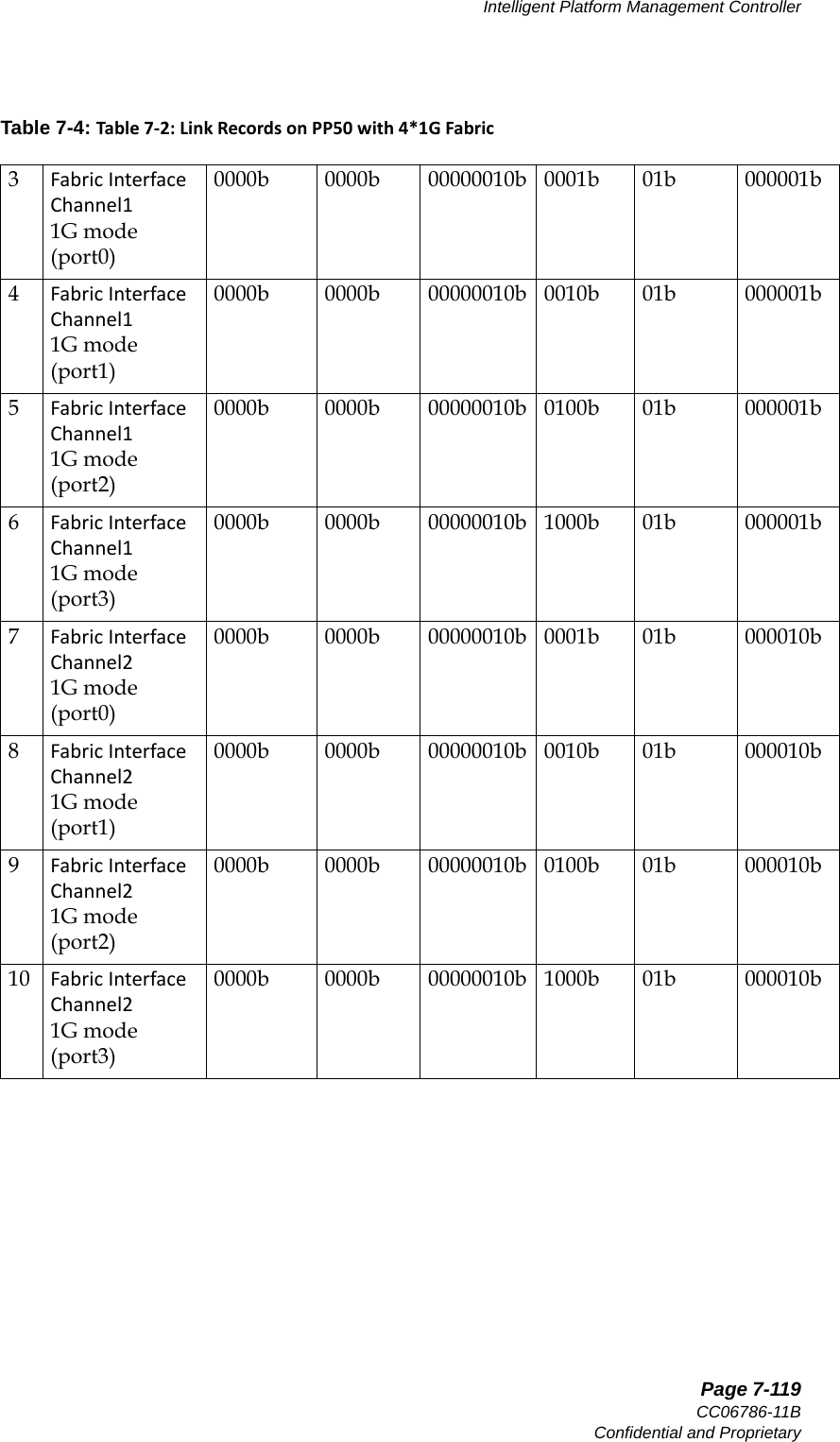
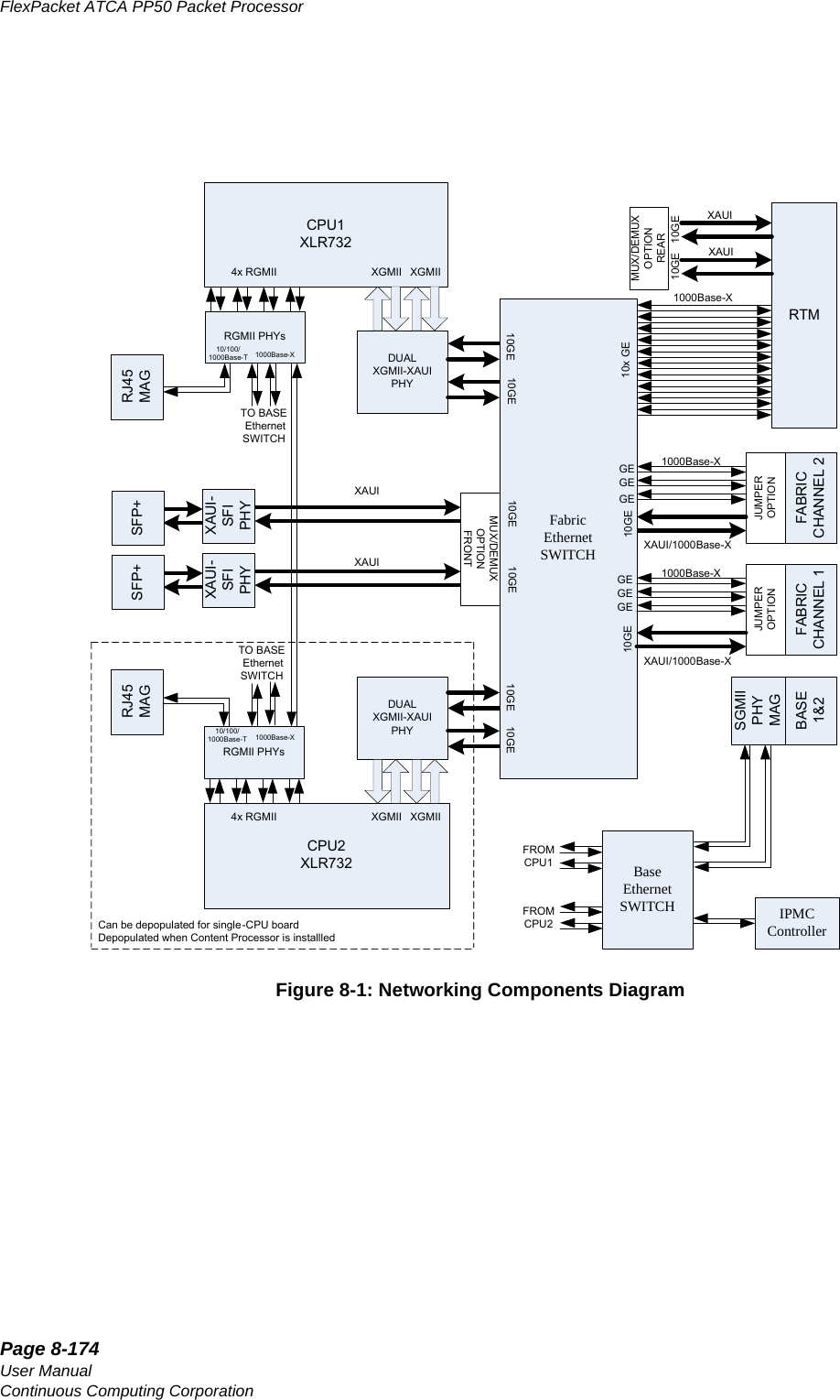
![Page 7-118User ManualContinuous Computing CorporationFlexPacket ATCA PP50 Packet Processor Preliminary7.3 Link DescriptorsThere are two fabric configurations for the PP50: •10G Fabric •4*1G FabricFollowing table lists the link descriptors used for the 10G fabric and 4*1G Fabric.Table 7-3: LinkRecordsonPP50with10GFabric# Description Link Grouping ID [31:24]Link Type Exten-sion [23:20]Link Type [19:12]Port Flags [11:8]Interface [7:6] Channel [5:0]1BaseInterfaceChannel 10000b 0000b 00000001b 0001b 00b 000001b2BaseInterfaceChannel20000b 0000b 00000001b 0001b 00b 000010b3FabricInterfaceChannel110G mode0000b 0001b 00000010b 1111b 01b 000001b4FabricInterfaceChannel11G mode0000b 0000b 00000010b 0001b 01b 000001b5 FabricInterfaceChannel210G mode0000b 0001b 00000010b 1111b 01b 000010b6FabricInterfaceChannel21G mode0000b 0000b 00000010b 0001b 01b 000010bTable 7-4: Table7‐2:LinkRecordsonPP50with4*1GFabric# Description Link Grouping ID [31:24]Link Type Exten-sion [23:20]Link Type [10:12]Port Flags [11:8]Interface [7:6] Channel [5:0]1BaseInterfaceChannel 10000b 0000b 00000001b 0001b 00b 000001b2BaseInterfaceChannel20000b 0000b 00000001b 0001b 00b 000010b](https://usermanual.wiki/UTStarcom/MSG2000/User-Guide-2403206-Page-116.png)
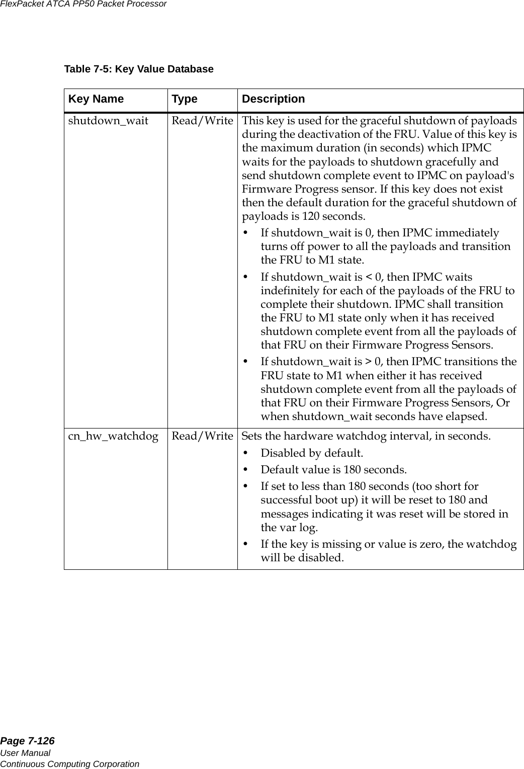
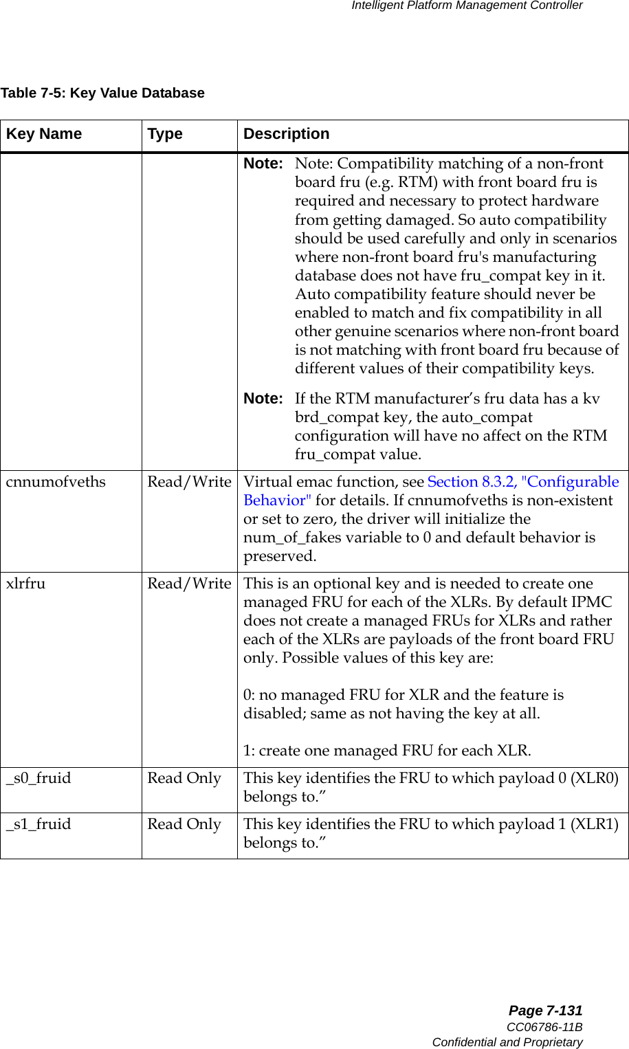
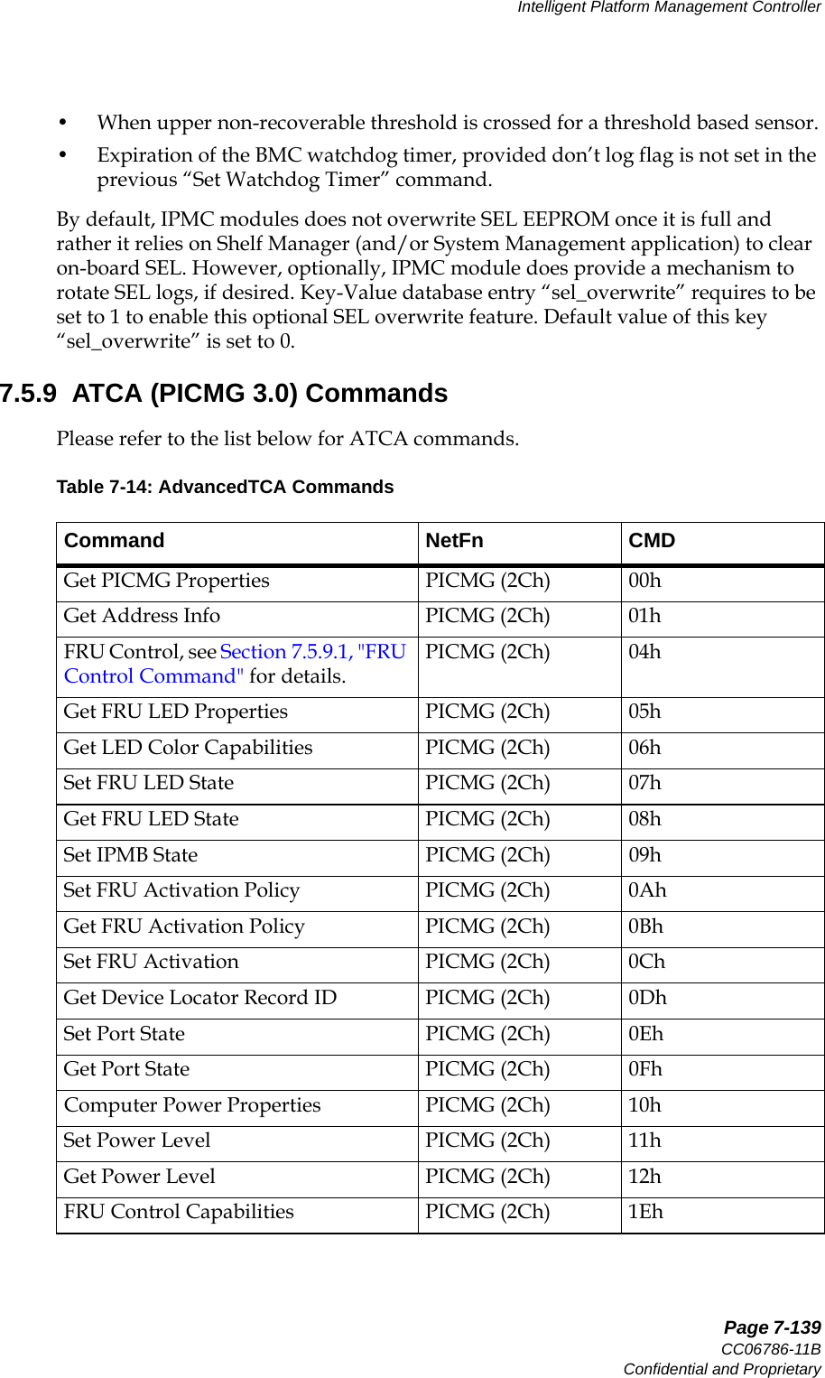
![Page 7-129CC06786-11BConfidential and ProprietaryIntelligent Platform Management Controller14ABABPreliminarydns_ns1 Read / WriteIP address of DNS server 1. This is used only when interface protocol is set to "static" and the key dnsdomain is set to "enable".dns_ns2 Read / WriteIP address of DNS server 2. This is used only when interface protocol is set to "static" and the key dnsdomain is set to "enable".sysid Read / WriteThis is an optional key and can be useful in multi-shelf system. This key is used in building dhcp client identifier for CNode's DHCP discover message. Client id has the format of [$sysid]-[$shelfid]-$hwaddr-cn-bsa for eth0 interface and [$sysid]-[$shelfid]-$hwaddr-cn-bsb for eth0.4094 interface. This key can be assigned any integer value.shelfid Read / WriteThis is an optional key and can be useful in multi-shelf system. This key is used in building dhcp client identifier for CNode's DHCP discover message. Client id has the format of [$sysid]-[$shelfid]-$hwaddr-cn-bsa for eth0 interface and [$sysid]-[$shelfid]-$hwaddr-cn-bsb for eth0.4094 interface. This key can be assigned any integer value.ntpserver Read / WriteAddress of NTP server. If this key is set then ntpclient on CNode adjusts time using the specified server. CCPU has reserved following ntp servers and user can set this key to point to any of these server addresses: "0.ccpu.pool.ntp.org", "1.ccpu.pool.ntp.org", "2.ccpu.pool.ntp.org", "3.ccpu.pool.ntp.org".sel_overwrite Read / WriteThis is an optional key to enable SEL overwriting. Possible values are: 0 or 1. CNode has a 4K bytes of EEPROM for on-board SEL (System Event Logging). IPMC module only writes critical events in SEL, though all the events are sent to Shelf Manager (if enabled). By default (if this key is not configured, Or if this key is configured and set to 0), IPMC would not overwrite SEL EEPROM once it is full and rather would rely on Shelf Manager (and/or System Management application) to clear on-board SEL. If this key is set to 1, then IPMC shall rotate SEL logs (as a circular buffer) once it is full.Table 7-5: Key Value DatabaseKey Name Type Description](https://usermanual.wiki/UTStarcom/MSG2000/User-Guide-2403206-Page-127.png)
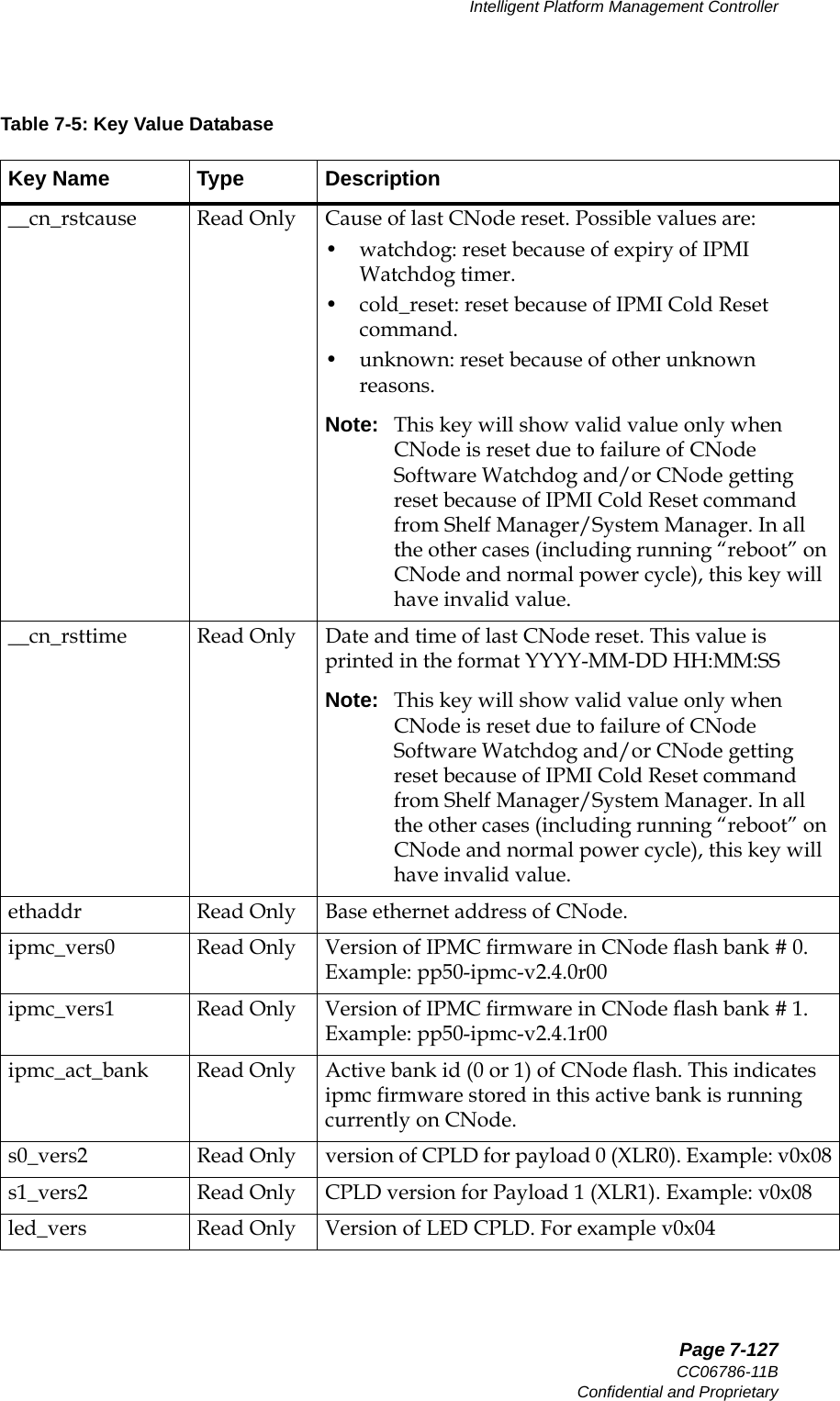
![Page 7-132User ManualContinuous Computing CorporationFlexPacket ATCA PP50 Packet Processor Preliminary7.4.2 To List All Key Value EntriesUsage: cnodekvTypical Output (your output may be different):_s0_fwprogid Read Only This key identifies the Firmware Progress Sensor for the payload 0 (XLR0). Payload requires the sensor id to send events and status to IPMC using “Set Sensor Reading and Event Status” command on its Firmware Progress Sensor._s1_fwprogid Read Only This key identifies the Firmware Progress Sensor for the payload 1 (XLR1). Payload requires the sensor id to send events and status to IPMC using “Set Sensor Reading and Event Status” command on its Firmware Progress Sensor.s[0|1]_multiboot Read/Write See Section6.2.1.9, "Initializing Multiboot" for details.s[0|1]_bootdelay Read/Write See Section6.2.1.9.3, "Setting the s[0_1]_multiboot Key Value" for details.cn_wd_report Read Only Watchdog report key. For internal use only. root@cnode-pp50:~ cnodekvipmc_version = pp50-ipmc-v2.4.0r00datetime = 2009-02-21 00:40:14epochtime = 1235176814xlr0base = 00:02:bb:50:02:00xlr1base = 00:02:bb:50:02:08hwaddr = 45f1_presence = 1f2_presence = 1__pwr_regs = ff00000000000000__f0_poh = 713__s0_rstcause = pwrcycle__s0_rsttime = 2009-02-20 23:16:40__s1_rstcause = pwrcycle__s1_rsttime = 2009-02-20 23:16:40__cn_rstcause = cold_reset__cn_rsttime = 2009-02-12 19:02:36fswitchCfg = /etc/fswitchCfg.defroute10g = faceplateethaddr = 00:02:bb:50:02:06ntpserver = 0.ccpu.pool.ntp.orgsel_overwrite = 0s0_act_bank = 0s1_act_bank = 0Table 7-5: Key Value DatabaseKey Name Type Description](https://usermanual.wiki/UTStarcom/MSG2000/User-Guide-2403206-Page-130.png)


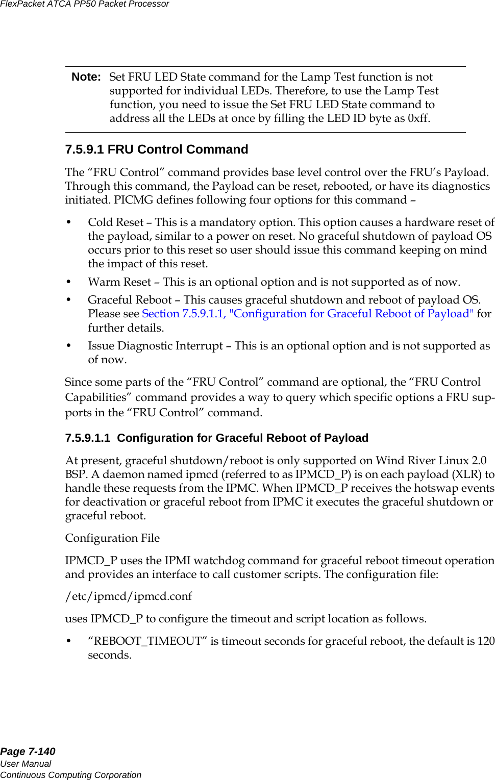
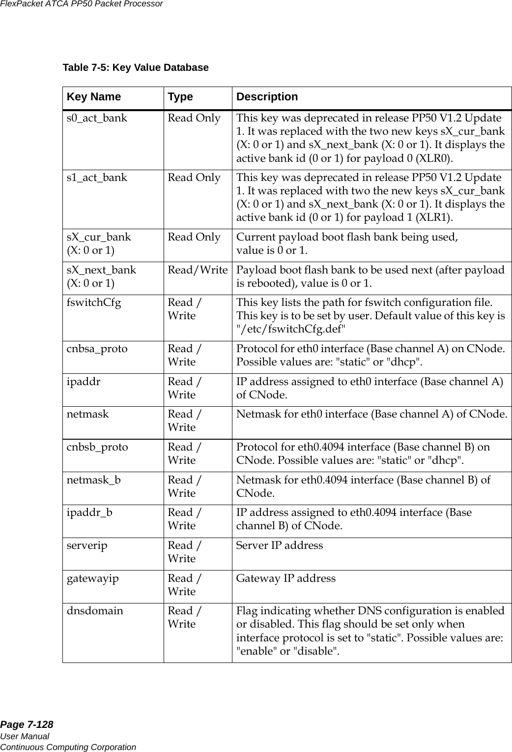
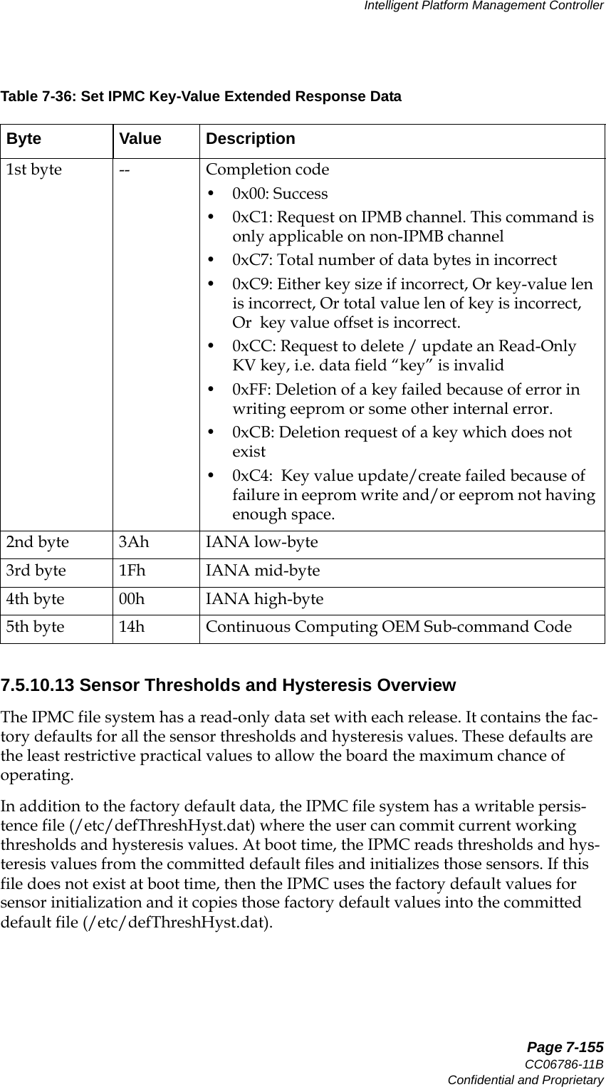
![Page 7-149CC06786-11BConfidential and ProprietaryIntelligent Platform Management Controller14ABABPreliminary7.5.10.8 Get IPMC Key NCommand: 50hSub-command: 10h.Table 7-27: Get IPMC Key N Request DataByte Value Description1st byte 3Ah IANA low-byte2nd byte 1Fh IANA mid-byte3rd byte 00h IANA high-byte4th byte 10h Continuous Computing OEM Subcommand Code5th byte - index of “key” to retrieveTable 7-28: Get IPMC Key N Response DataByte Value Description1st byte -- Completion Code:• 0x00: Success.• 0xC7: Total number of data bytes is incorrect.2nd byte 3Ah IANA low-byte3rd byte 1Fh IANA mid-byte4th byte 00h IANA high-byte5th byte 10h Continuous Computing OEM Subcommand Code6th byte n length of the “key”0 = invalid key index was specified in the request1 to 14 = number of bytes of “value” that follow[7:6+n] - “key” bytes, 1 to 14 bytes](https://usermanual.wiki/UTStarcom/MSG2000/User-Guide-2403206-Page-147.png)
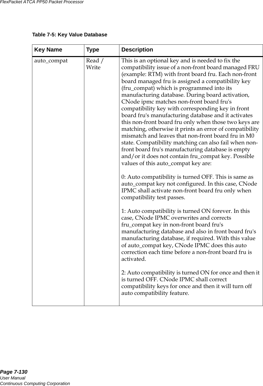
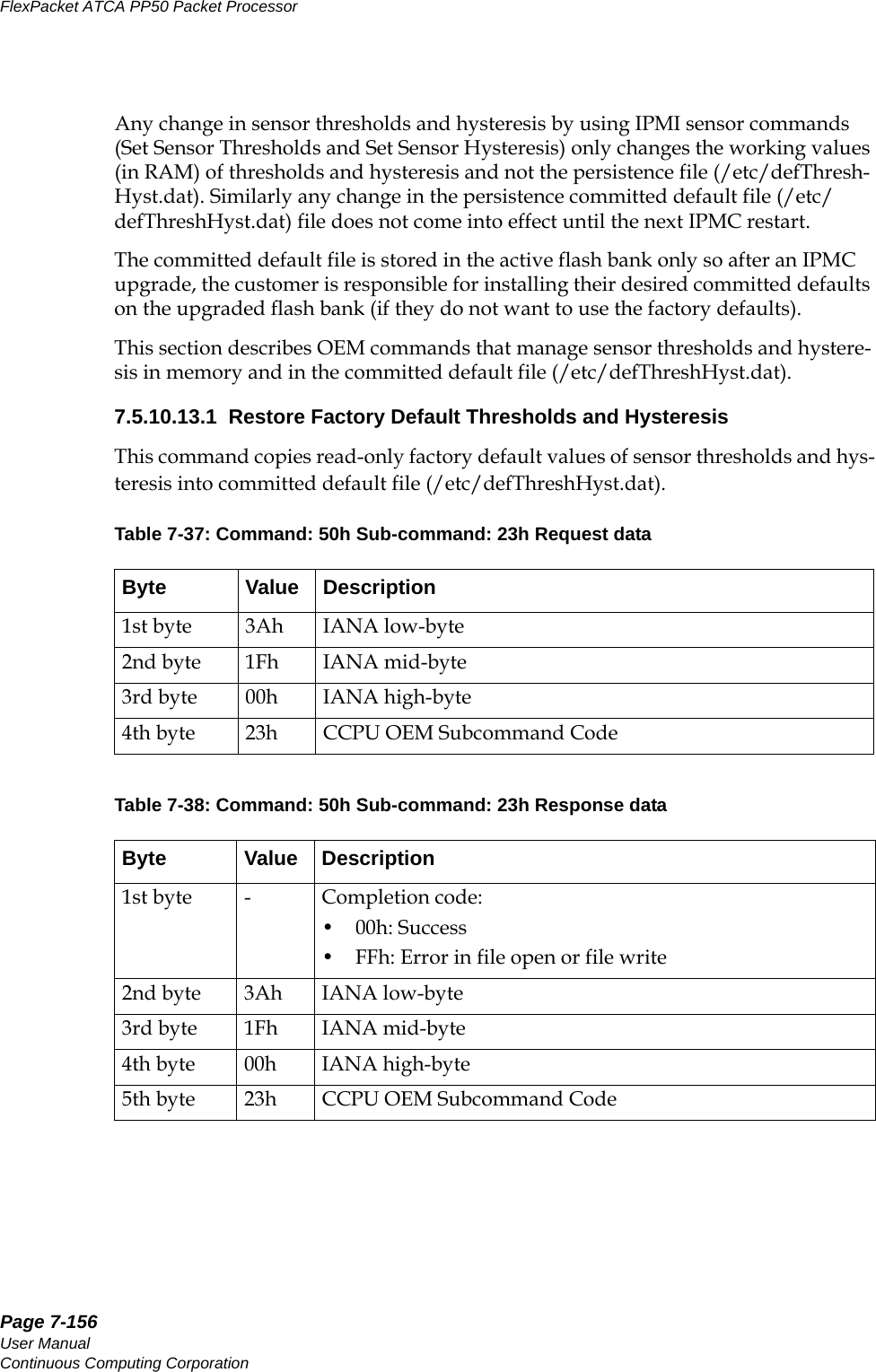
![Page 7-150User ManualContinuous Computing CorporationFlexPacket ATCA PP50 Packet Processor Preliminary7.5.10.9 Get IPMC Key-ValueCommand: 50hSub-command: 11h.Table 7-29: Get IPMC Key-Value Request DataByte Value Description1st byte 3Ah IANA low-byte2nd byte 1Fh IANA mid-byte3rd byte 00h IANA high-byte4th byte 11h Continuous Computing OEM Subcommand Code5th byte m 1 to 14 = number of bytes of “key” that follow6th byte n 1 to 16 = number of bytes of “value” to retrieve7th byte o 0 to 31 = offset of “value” to retrieve[8:7+m] - “key” bytes, 1 to 14 bytes longTable 7-30: Get IPMC Key-Value Response DataByte Value Description1st byte -- Completion Code:• 0x00: Success.• 0xC7: Total number of data bytes is incorrect. • 0xC9: Either key size is incorrect, key-value len is incorrect, or key value offset is incorrect. 2nd byte 3Ah IANA low-byte3rd byte 1Fh IANA mid-byte4th byte 00h IANA high-byte5th byte 11h Continuous Computing OEM Subcommand Code6th byte m 1 to 32 = total size of the “value” 7th byte o 0 = invalid “key” or offset was specified in the request1 to 16 = number of bytes of “value” that follow[8:7+n] - “value” bytes, 1 to 16 bytes](https://usermanual.wiki/UTStarcom/MSG2000/User-Guide-2403206-Page-148.png)
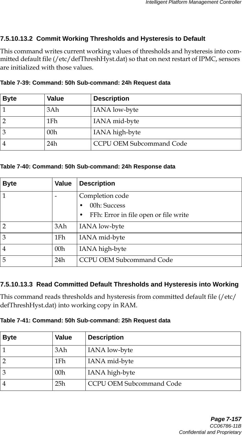
![Page 7-151CC06786-11BConfidential and ProprietaryIntelligent Platform Management Controller14ABABPreliminary7.5.10.10 Set IPMC Key-ValueCommand: 50hSub-command: 12h.Table 7-31: Set IPMC Key-Value Request DataByte Value Description1st byte 3Ah IANA low-byte2nd byte 1Fh IANA mid-byte3rd byte 00h IANA high-byte4th byte 12h Continuous Computing OEM Subcommand Code5th byte m 1 to 14 = number of bytes of “key”6th byte n number of “value” bytes that follow 0 = delete the key/value entry1 to 8 = number of “value” bytes7th byte - total size of the “value” 0 = delete the key/value entry1 to 32 = total length of the “value”8th byte - 0 to 31 = offset of the “value” to set[9:8+m] - “key” bytes, where m = 1 to 14[9+m:8+m+n] - “value” bytes, where n = 1 to 8](https://usermanual.wiki/UTStarcom/MSG2000/User-Guide-2403206-Page-149.png)
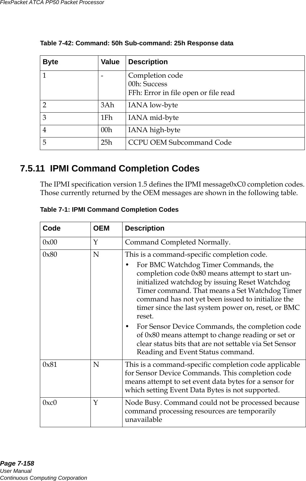
![Page 7-153CC06786-11BConfidential and ProprietaryIntelligent Platform Management Controller14ABABPreliminary7.5.10.11 Get IPMC Key-Value ExtendedThis is an extended version of “Get IPMC Key-Value” command. This command is only applicable on a non-IPMB channel (for example, payload channel or Direct RMCP to CNode). This command allows user to request complete key value length of 32 bytes in one single Get Key value request message.Command: 50hSub-command: 13h . Table 7-33: Get IPMC Key-Value Extended Request DataByte Value Description1st byte 3Ah IANA low-byte2nd byte 1Fh IANA mid-byte3rd byte 00h IANA high-byte4th byte 13h Continuous Computing OEM Sub-command Code5th byte m 1 to 14 = number of bytes of “key” that follow6th byte n 1 to 32 = number of bytes of “value” to retrieve7th byte o 0 to 31 = offset of “value” to retrieve[8:7+m] - “key” bytes, 1 to 14 bytes longTable 7-34: Get IPMC Key-Value Extended Response DataByte Value Description1st byte -- Completion code:• 0xC7: Total number of data bytes is incorrect.0x00: Success• 0xC1: Request on IPMB channel. This command is only applicable on non-IPMB channel• 0xC7: Total number of data bytes in incorrect• 0xC9: Either key size if incorrect, key-value len is incorrect, or key value offset is incorrect.2nd byte 3Ah IANA low-byte3rd byte 1Fh IANA mid-byte](https://usermanual.wiki/UTStarcom/MSG2000/User-Guide-2403206-Page-151.png)
![Page 7-154User ManualContinuous Computing CorporationFlexPacket ATCA PP50 Packet Processor Preliminary7.5.10.12 Set IPMC Key-Value ExtendedThis is an extended version of “Set IPMC Key-Value” command. This command is only applicable on a non-IPMB channel (for example, payload channel or Direct RMCP to CNode). This command allows user to set complete key value length of 32 bytes in one single Set Key value request message.Command: 50hSub-command: 14h.4th byte 00h IANA high-byte5th byte 13h Continuous Computing OEM Sub-command Code6th byte m 1 to 32 = total size of the “value”7th byte o 0 = invalid “key” or offset was specified in the request1 to 32 = number of bytes of “value” that follow[8:7+n] - “value” bytes, 1 to 32 bytesTable 7-35: Set IPMC Key-Value Extended Request DataByte Value Description1st byte 3Ah IANA low-byte2nd byte 1Fh IANA mid-byte3rd byte 00h IANA high-byte4th byte 14h Continuous Computing OEM Sub-command Code5th byte m 1 to 14 = number of bytes of “key” that follow6th byte n Number of “value” bytes that follow0 = delete the key/value entry1 to 32 = number of “value” bytes7th byte - Total size of the “value”0 = delete the key/value entry1 to 32 = total length of the “value”8th byte - 0 to 31 = offset of the “value” to set[9:8+m] - “key” bytes, where m = 1 to 14[9+m:8+m+n] - “value” bytes, where n = 1 to 32Table 7-34: Get IPMC Key-Value Extended Response Data](https://usermanual.wiki/UTStarcom/MSG2000/User-Guide-2403206-Page-152.png)
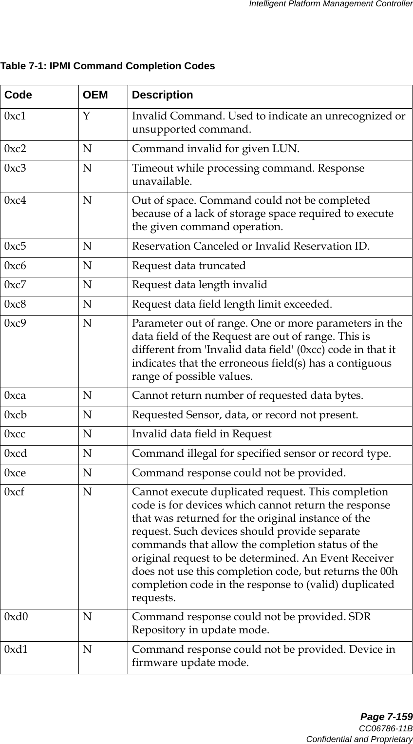
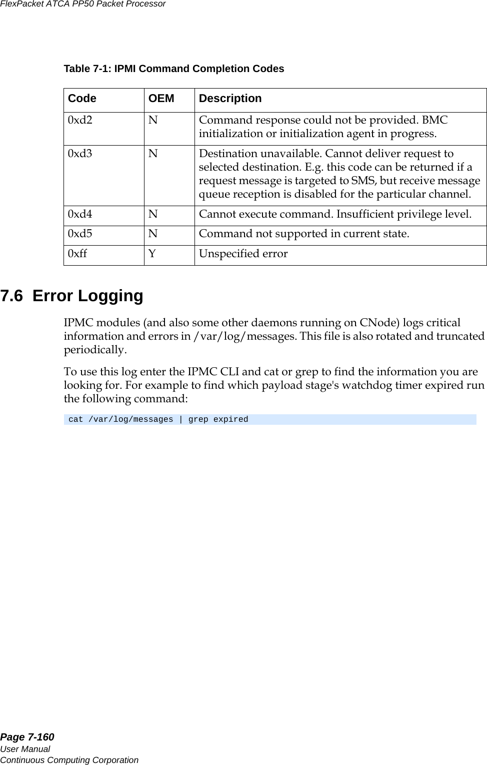
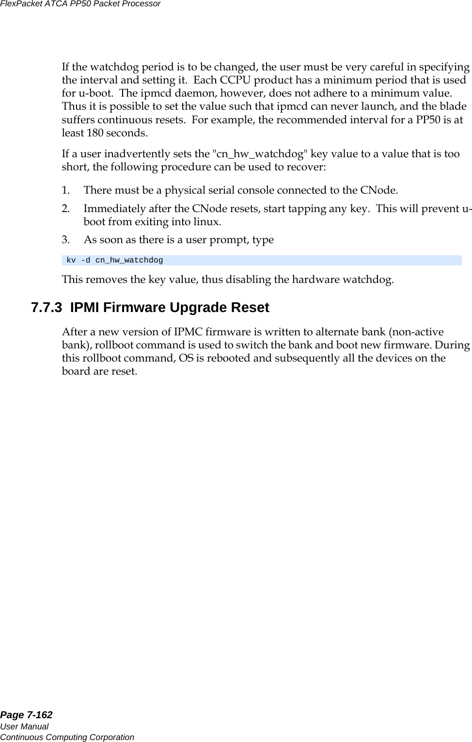
![Page 7-161CC06786-11BConfidential and ProprietaryIntelligent Platform Management Controller14ABABPreliminary7.7 Behavior of IPMI ResetsThe PP50 supports the following types of IPMI resets.7.7.1 IPMI Cold ResetDuring the IPMI Cold Reset all board devices are reset. The same actions are taken when the CNode is rebooted using Linux “reboot” command.7.7.2 IPMI Watchdog ResetThere are two levels of watchdog functionality in the CNode: •Linux Application Level•Hardware Level7.7.2.1 Linux Application LevelCertain CCPU applications and daemons (ipmcd, rfswitchd, ipmc-cli) are moni-tored by a parent process. For example, rfswitchd forks to a child process, also named rfswitchd. If the child terminates, the parent will restart it. The exceptions to this are if the termination is due to the child receiving a SIGTERM or SIGKILL. In this case, the parent will terminate itself via a call to exit(). This behavior allows the user or another process to kill an application-level-protected process.7.7.2.2 Hardware LevelCertain user applications require an autonomous reset of the system under certain fatal conditions. The hardware-level watchdog monitors two software entities: • u-boot (the boot monitor)• ipmcd (the IPMI control daemon running in linux). The u-boot watchdog resets the CNode (which power-cycles the payloads) if Linux fails to boot. The ipmcd watchdog will reset the CNode if ipmcd hangs or stops exe-cution for any reason. The CCPU hardware watchdog is a discrete chip that continues to operate even if the processor(s) are not.The key value "cn_hw_watchdog" controls the watchdog period. If it exists and has a non-zero value, the hardware watchdog is programmed to fire (reset the CNode) in [cn_hw_watchdog] seconds. The responsible software entity (u-boot or ipmcd) is responsible for re-starting the hardware watchdog periodically - before it has a chance to fire. If the key value database item "cn_hw_watchdog" is set to zero or is non-existent, the hardware watchdog is disabled.](https://usermanual.wiki/UTStarcom/MSG2000/User-Guide-2403206-Page-159.png)
![Page 7-163CC06786-11BConfidential and ProprietaryIntelligent Platform Management Controller14ABABPreliminary7.8 IPMC Command Line InterfaceThe CNode provides an IPMC command line interface (IPMC-CLI) to control and configure IPMC resources on the board. The IPMC-CLI connects to the IPMC dae-mon (ipmcd) over an RMCP channel established locally and acts as a RMCP client of the IPMC daemon, therefore the IPMC-CLI only works when an IPMC daemon is running in the system. The IPMC daemon is started by the CNode Linux boot startup scripts; by default the daemon is running when one logs into the CNode.The IPMC-CLI can be run either in an interactive mode or in a non-interactive mode. In interactive mode, the IPMC-CLI is invoked by running "ipmc-cli" from CNode Linux prompt. It displays a CLI prompt where user needs to enter a command. On command completion, the CLI returns back to its prompt. The CLI prompt is shown below.Where, address - ipmb slave address of the board in the chassis. Example:To exit from CLI, either type "quit" and hit enter key or press Control-c (^c).In the non-interactive mode, CLI command is entered at the CNode Linux prompt itself as shown below.The following subsections list all the commands supported by IPMC-CLI and their usage description.pp50-<address>-ipmc-cli >pp50-0x86-ipmc-cli>Note: In the interactive mode of operation, IPMC-CLI does not support command history (pressing up/down arrow key).ipmc-cli <command> [command parameters]](https://usermanual.wiki/UTStarcom/MSG2000/User-Guide-2403206-Page-161.png)
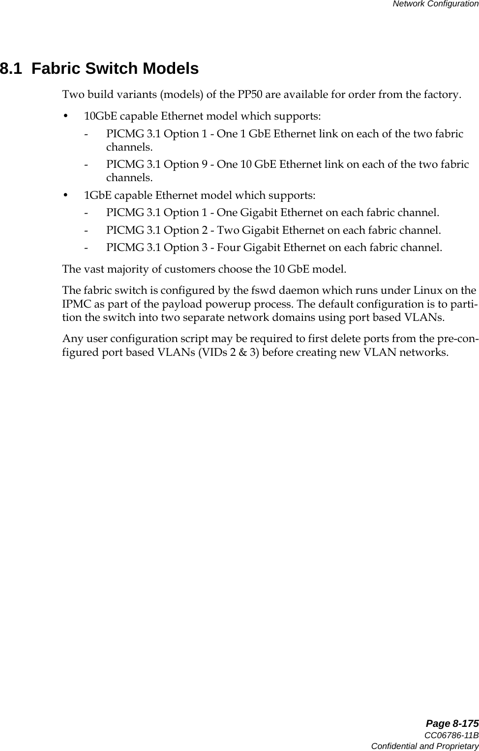
![Page 7-164User ManualContinuous Computing CorporationFlexPacket ATCA PP50 Packet Processor Preliminary7.8.1 bmc_watchdogThis command is to Get / Set / Reset BMC Watchdog Timer for a payload CPU.Command syntax:bmc_watchdog <payId> [on <duration> <action> | off | restart]Where,payId - payload id. Run the command "listpay" to get list of all the payloads on the board. To get the current status of watchdog timer, run the command with just the payload id.on | off - turns on/off timerrestart - restarts an already running timerduration - timer duration in unit of secondsaction - timer expiry action. Actions can be - hardreset - hard reset payload on expiry of timer noaction - timer expiry is logged in SEL and syslog but no action taken on payloadThis command sends PICMG command Get/Set/Reset BMC Watchdog Timer to IPMC daemon. When starting the watchdog timer, this command sets OEM into the fields – “Timer Use” and “Timer Use Expiration Flag Clear” bytes of Set BMC Watchdog Timer command.Example:7.8.2 commitThis command commits current working thresholds and hysteresis values of sen-sors into persistence as a customer committed defaults.Command Syntax:pp50-0x86-ipmc-cli> bmc_watchdog 0 on 30 hardresetSet Watchdog Timer successfulpp50-0x86-ipmc-cli> bmc_watchdog 0BMC Watchdog timer is runningLogging of timer expiry event is enabledTimer Use: 0x45Timer Action: Hard reset on expiry of timerTimer Use Expiration Flag Clear: 0x00Initial Countdown (Timer Duration): 30 secondsPresent Countdown (Remaining Timer Duration): 20 seconds](https://usermanual.wiki/UTStarcom/MSG2000/User-Guide-2403206-Page-162.png)
![Page 7-165CC06786-11BConfidential and ProprietaryIntelligent Platform Management Controller14ABABPreliminarycommit <threshhyst>Example:7.8.3 debuglevelThis command gets / sets debug level of IPMC daemon process. IPMC daemon pro-cess logs information into /var/log/messages as per the debug level set. This command is mostly used for debugging purposes. Command syntax:debuglevel [level]If level is not specified then displays the current debug level of IPMC. If level is specified then sets the debug level of IPMC.Levels are - 0 - CNLOG_EMERG1 - CNLOG_ALERT2 - CNLOG_CRIT3 - CNLOG_ERR4 - CNLOG_WARNING5 - CNLOG_NOTICE6 - CNLOG_INFO7 - CNLOG_DEBUGExample:7.8.4 getactivebankDisplays active bank id of a firmware upgradable device. List of firmware upgrad-able devices on the board can be found by running command “listfwdev”.Command syntax:getactivebank <fwDevId>Where,fwDevId: Firmware upgradable device id, can be found by running "listfwdev" command.pp50-0x86-ipmc-cli> commit threshhystCommit threshhyst successfulpp50-0x86-ipmc-cli> debuglevelIPMC Debug Level is 5 (CNLOG_NOTICE)pp50-0x86-ipmc-cli> debuglevel 6IPMC Debug Level set to 6 (CNLOG_INFO)](https://usermanual.wiki/UTStarcom/MSG2000/User-Guide-2403206-Page-163.png)
![Page 7-166User ManualContinuous Computing CorporationFlexPacket ATCA PP50 Packet Processor PreliminaryExample:7.8.5 getresetstatusDisplays reset status of a resettable device on the board. List of resettable devices on the board can be found by running command “listdev”.Command syntax:getresetstatus <devId>Example:7.8.6 helpLists all the commands or usage on a particular command.Command syntax:help <command name>When a command name is specified then it displays usage information about that command. When a command name is not specified then it lists all the available commands.Example:pp50-0x86-ipmc-cli> getactivebank 0fwDeviId: 00, Active Bank Id: 0pp50-0x86-ipmc-cli> getresetstatus 1Device in reset off statepp50-0x86-ipmc-cli> helpCNode IPMC CLI Command Set - Command name and parameters are case sensitive.bmc_watchdog <payId> [on <duration> <action> | off | restart]commit <threshhyst>debuglevel [level]getactivebank <fwDevId>getresetstatus <devId>kv [ [-p] key | key value | -d key | -h ]listdevlistfwdevlistpaylocaladdressquitresetdev <devId>restore [factory | custom] <threshhyst>sel [info | clear | rotate <on | off>] [add <16 bytes (in hex)>]sendcmd <netFn> <cmd> [data bytes]setactivebank <fwDevId> <bankId>setresetstatus <devId> <resetState>version [all]](https://usermanual.wiki/UTStarcom/MSG2000/User-Guide-2403206-Page-164.png)
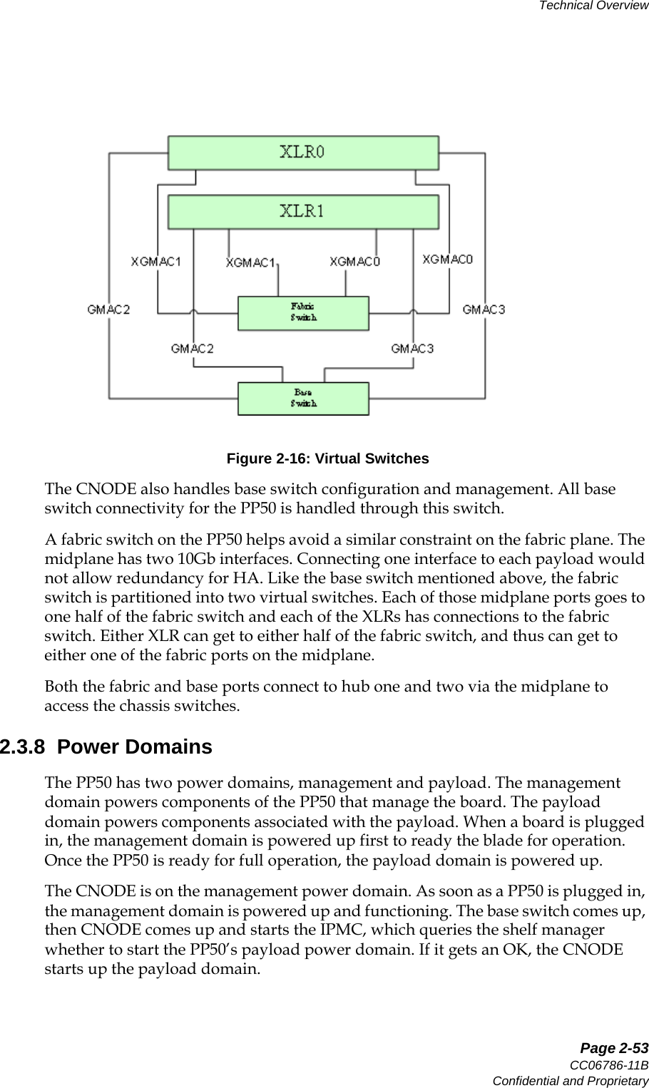
![Page 7-167CC06786-11BConfidential and ProprietaryIntelligent Platform Management Controller14ABABPreliminary7.8.7 kvThis command is to manipulate Key-Value database.Command syntax:kv [ [-p] key | key value | -d key | -h ]Where,-p : print key name along with value-d : delete a key-h : display usageWhen no any argument is supplied then lists all the key-values.Example:pp50-0x86-ipmc-cli> help versionDisplay version of the components.Usage:version [all]When option "all" is specified then displays version of all the components, otherwise displays version of IPMC f/w.pp50-0x86-ipmc-cli> kvipmc_version = pp50-ipmc-v2.6.3r00datetime = 2010-08-13 21:40:39epochtime = 1281735639s0_mac_base = 00:02:bb:50:03:90s1_mac_base = 00:02:bb:50:03:98xlr0base = 00:02:bb:50:03:90xlr1base = 00:02:bb:50:03:98f0_brd_compat = unknownf1_brd_compat = notinstalledf2_brd_compat = notinstalledhwaddr = 43f1_presence = 0f2_presence = 0tcam_fpga_vers = not_presents0_cur_bank = 1s1_cur_bank = 1__pwr_regs = f500000000000000__f0_poh = 12983__s0_rstcause = pwrcycle__s0_rsttime = 2010-08-13 21:38:40_s0_state = INIT_s0_fruid = 0_s0_fwprogid = 9__s1_rstcause = pwrcycle__s1_rsttime = 2010-08-13 21:38:40_s1_state = INIT_s1_fruid = 0_s1_fwprogid = 13__cn_rstcause = cold_reset](https://usermanual.wiki/UTStarcom/MSG2000/User-Guide-2403206-Page-165.png)
![Page 7-169CC06786-11BConfidential and ProprietaryIntelligent Platform Management Controller14ABABPreliminary7.8.11 localaddressDisplays Logical slot id, HW address and IPMB Slave address of the board.Command syntax:localaddressExample:7.8.12 quitUse this command to exit the CLI. Alternatively, you can also press Control-c(^c) to exit from the CLI.This command gracefully shuts down the ipmc-cli. During shutdown it closes the RMCP session with IPMC daemon. Always gracefully exit from the IPMC-CLI to avoid hanging sessions on the IPMC daemon side. Future release of ipmc f/w may support periodic audit of RMCP sessions at IPMC daemon to clear all the idle sessions. 7.8.13 resetdevHard resets a device on the board. List of resettable devices on the board can be found by running command “listdev”.Command syntax:resetdev <devId>Example:7.8.14 restoreRestores sensor thresholds and hysteresis data to either factory defaults or customer committed default values.Command syntax:restore [factory | custom] <threshhyst>pp50-0x86-ipmc-cli> localaddressLogical slot id: 0x03, HW Address: 0x43, IPMB Slave Address: 0x86pp50-0x86-ipmc-cli> resetdev 0 Device reset successfulNote: This command replaces customer committed thresholds and hysteresis data with factory default values and loads those factory default values into working copy in RAM.](https://usermanual.wiki/UTStarcom/MSG2000/User-Guide-2403206-Page-167.png)
![Page 7-170User ManualContinuous Computing CorporationFlexPacket ATCA PP50 Packet Processor PreliminaryExample:7.8.15 selThis command is for onboard SEL device.Command syntax: sel [info | clear | rotate <on | off>] [add <16 bytes (in hex)>]Where,The command without any parameters displays all log entries.info - display SEL version, free space, time stamp etc. clear - clear all the entries in SELrotate <on | off> - turn ON/OFF SEL overwrite in circular fashionadd - add 16 bytes of entry (in hex) into the SELNote: IPMC only logs most critical events in the on-board SEL.Example:7.8.16 sendcmdSends a RAW IPMI message to IPMC daemon process.Command syntax:sendcmd <netFn> <cmd> [data bytes]All parameters should be in Hex.Where,netFn: Net function as per ATCA/IPMI specificationcmd: Command code byte as per ATCA/IPMI specificationparameters: Command parameters bytes.Example:pp50-0x86-ipmc-cli> restore factory threshhystRestore factory default of threshhyst successfulpp50-0x86-ipmc-cli> sel infoSEL Version: 1.5Number of log entries: 1Free Space (in bytes): 4048Most recent addition timestamp: 2010-08-12 14:33:05Most recent erase timestamp: 2010-08-11 00:32:37Supported operations: 0x00pp50-0x86-ipmc-cli> sel 0x0001: Event: at 2010-08-12 14:33:05; from:(0x86,0x00,0x00); sensor:(0x23,0x0c); event: 0x6f(asserted); event data1: 0x01, event data2: 0x05, event data3: 0x00](https://usermanual.wiki/UTStarcom/MSG2000/User-Guide-2403206-Page-168.png)
![Page 7-172User ManualContinuous Computing CorporationFlexPacket ATCA PP50 Packet Processor PreliminaryCommand syntax: version [all]When option "all" is specified then displays version of all the IPMC f/w compo-nents, otherwise displays version of IPMC f/w.Example:pp50-0x86-ipmc-cli> versionipmc_version = t20100811-204706-rchuhanpp50-0x86-ipmc-cli> version allipmc_version = t20100811-204706-rchuhantcam_fpga_vers = not_presents0_vers2 = v0x08s1_vers2 = v0x08led_vers = v0x04](https://usermanual.wiki/UTStarcom/MSG2000/User-Guide-2403206-Page-170.png)
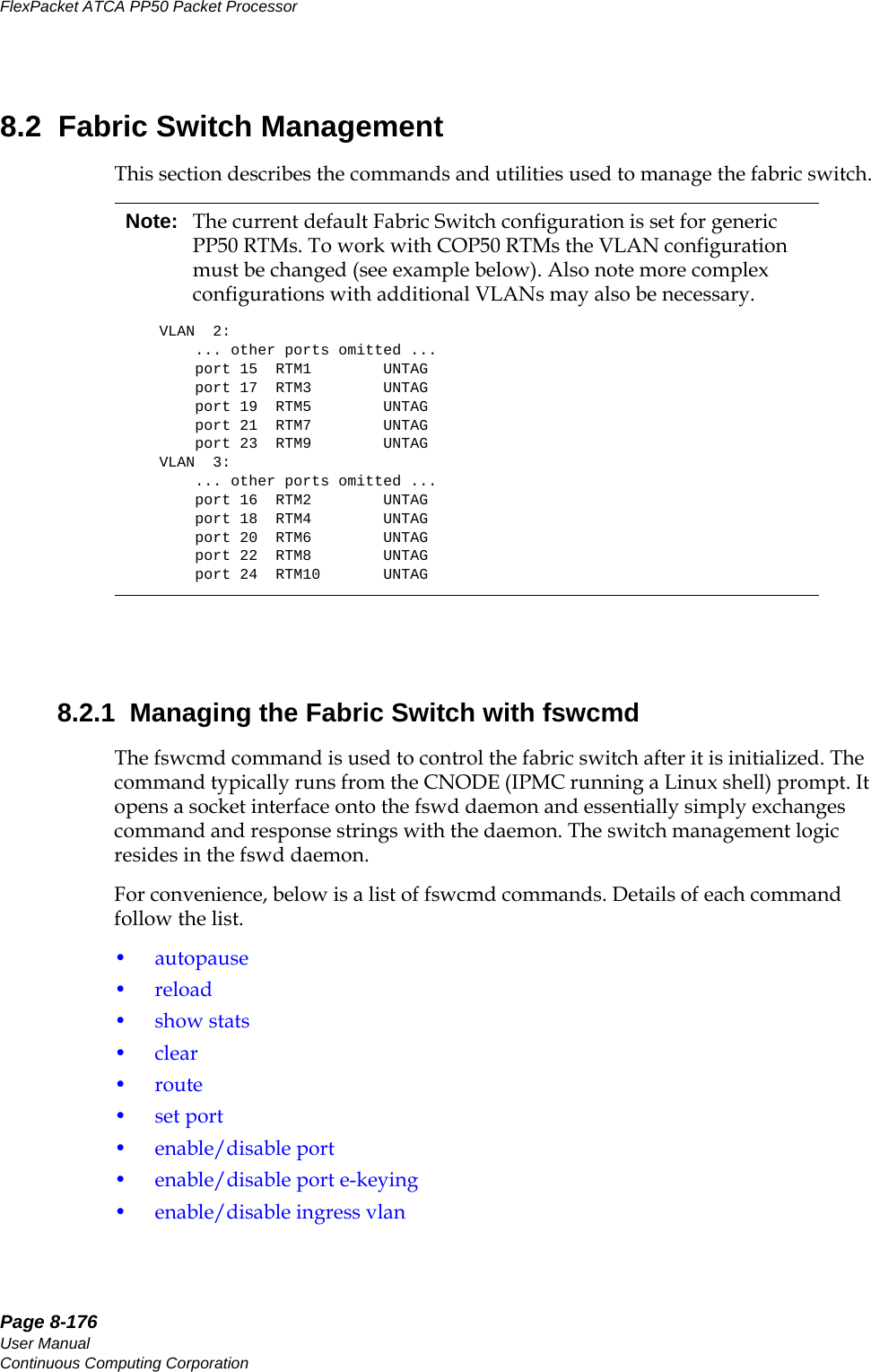
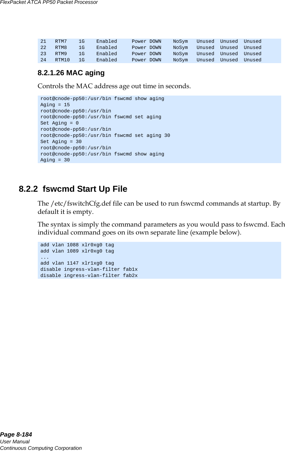
![Page 8-177CC06786-11BConfidential and ProprietaryNetwork Configuration14ABABPreliminary• enable/disable accept untagged port• set port default• add vlan•del vlan•show• SFP Commands• show Commands•cfgreg•dump•show version•dump• enable | disable mac-learning• enable | disable flooding broadcast• high and low watermark range• enable | disable protocol-traps• show link•MAC aging8.2.1.1 autopauseBy default the switch is in auto-pause mode and adjusts QOS parameters such as the watermark. Disables the auto-pause mode of the switch. The switch does not adjust QOS param-eters such as Watermark if auto pause is disabled.Enables the auto-pause mode of switch (default). The switch adjusts QOS parame-ters such as Watermark if auto pause enabled.Displays if auto-pause mode is enabled or disable for the switch.8.2.1.2 reloadRe-configures the fabric switch according to the config file. This command resets the switch and reconfigures it into the default configuration before running the identi-fied configuration file. fswcmd disable auto-pausefswcmd enable auto-pausefswcmd show auto-pausefswcmd reload config [<path><filename>]](https://usermanual.wiki/UTStarcom/MSG2000/User-Guide-2403206-Page-175.png)
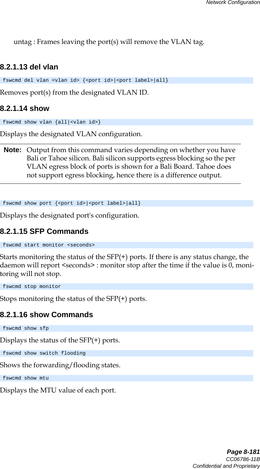
![Page 8-178User ManualContinuous Computing CorporationFlexPacket ATCA PP50 Packet Processor PreliminaryWhen the switch management daemon is activated, the config file is set by the key-value entry fswitchCfg. If the <filename> is not entered, the default filename /etc/fswitchCfg.def will be used, even if the key-value "fswitchCfg" is changed afterwards.8.2.1.3 show statsDisplays the port statistics.8.2.1.4 clearClears all ports' statistics.8.2.1.5 routeRoutes the two SFP+ ports to the RTM or faceplate. Note, they are both routed to the faceplate by default.8.2.1.6 set portSets the speed of the designated port.<speed>: [0, 10, 100, 1000, 10000]MbpsPlease note the following regarding this command:• If the EXTXG[1,2] speed is set to zero, the port speed will be configured according to the SFP(+) module installed• If the FAB[1,2]x speed is set to zero, the port speed is determined by ekeying• E-Keying Can be Enabled or Disabled per port • Front/Back 10G ports have 0,1G or 10G speed only• If the RTM[1,10] speed is set to zero, the port speed will be 10/100/1000 BASE-T auto-negotiation• Only OPTONE GLC-T-B Copper SFP supports 10/100/1000 BASE-T in RTMFiber and other Copper SFPs support force speed 1000M only in RTMSets the mtu of the designated port<mtu>: maximum frame size in bytesfswcmd show stats {all|<port id>|<port label>}fswcmd clear statsfswcmd route port {rtm|faceplate}fswcmd set port speed {<port id>|<port label>} <speed>fswcmd set port mtu {<port id>|<port label>} <mtu>](https://usermanual.wiki/UTStarcom/MSG2000/User-Guide-2403206-Page-176.png)
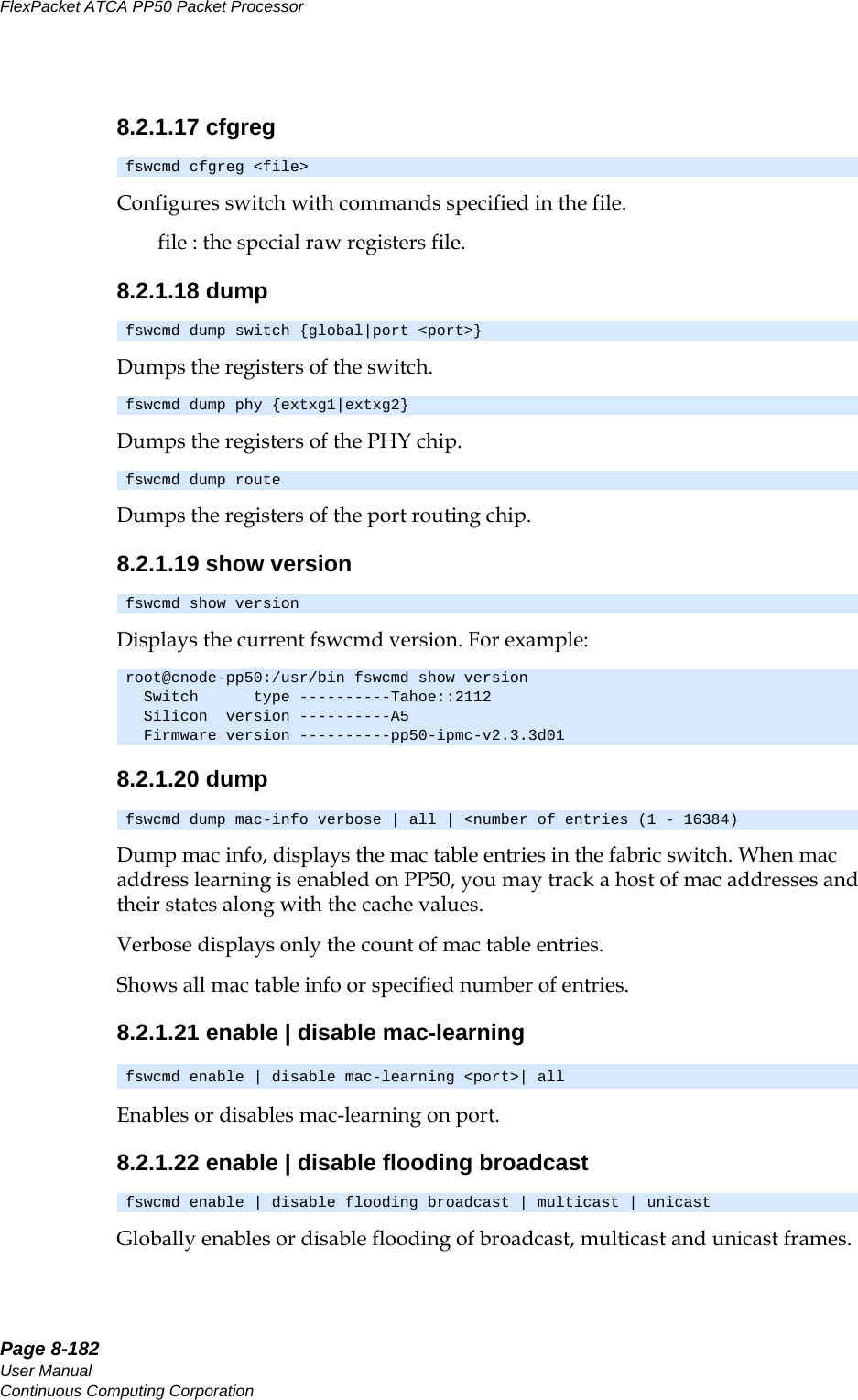
![Page 8-179CC06786-11BConfidential and ProprietaryNetwork Configuration14ABABPreliminaryNote, a specified value will be rounded down to the nearest multiple of 4.Applies the Transmit Watermark on the designated port in Kilobytes<tx-wm>: Range (255 - 1023)Applies the Receive Watermark on the designated port in kilobytes.<rx-wm>: Range (255 - 1023)Sets the Store forward Matrix from this source port to [1 . . 24] destination ports. This command should not be required in normal operation and its use is to be avoided if at all possible. - The default value is 0xFE000001 and bit 0 corresponds to CPU port .- 1 and 0 in bit positions 1 to 24 in Matrix are Store Forward and Cut Through respectively.- If the speed of this port is less than that of destination port, then (store forward) is recommended.- Store Forward Matrix is logical port map which sets the physical port accordingly.8.2.1.7 enable/disable portEnables the designated port.Disables the designated port.8.2.1.8 enable/disable port e-keyingThis command allows a system administrator to enable or disable e-keying on ports specified ports. The command applies to logical port s 7 through 14, FAB1X, FAB2X, FAB1 (A-D), or FAB2 (A-D).fswcmd set port tx-wm {<port id>|<port label>| all} <tx-wm>Note: Transmit Watermark is not supported on Bali silicon. root@cnode-pp50:~ fswcmd set port tx-wm&rx-wm 1 1000Tx Watermark Unsupported on Bali currentlyfswcmd set port rx-wm {<port id>|<port label> | all} <rx-wm>fswcmd set port store-forward {<port> <port label> | all} <value>fswcmd enable port {<port id>|<port label>}fswcmd disable port {<port id>|<port label>}fswcmd enable | disable e-key <port id| port label> | <all> \n);](https://usermanual.wiki/UTStarcom/MSG2000/User-Guide-2403206-Page-177.png)
![Page 8-180User ManualContinuous Computing CorporationFlexPacket ATCA PP50 Packet Processor PreliminaryE-key is enabled by default. Inclusion of multiple non fabric ports is ignored. By default, fabric ports process e-key messages. There may be times when these messages should be ignored. For example, if a system is using paddle boards instead of a switch (an FM40 for example), when the ShMC is rebooted, the fabric ports will be turned off because e-keying indicates there is no peer device to connect to. Disabling e-keying allows the fabric ports to remain open. 8.2.1.9 enable/disable ingress vlanEnables or disables ingress VLAN filter per port or all ports.8.2.1.10 enable/disable accept untagged portEnables or disables accepting untagged incoming data on port(s).Sets the tag mode of the designated port(s).tag-on-tag : If the frame leaves the switch tagged, it gets an additional VLAN tag. If the frame leaves the switch untagged, then any original VLAN is preserved, but this tag is not added.normal : the VLAN rules pertain to the traditional VLAN tag only.8.2.1.11 set port defaultSets the defaut VLAN ID and priority of the designated port(s).[<priority>] : the default priority, 0 by default.8.2.1.12 add vlanAdds port(s) to the designated VLAN ID.tag : Frames leaving the port(s) will keep the VLAN tag.fswcmd enable | disable ingress-vlan-filter <port> | allfswcmd enable | disable accept-untagged <port> | allNote: On PP50 boards with a Tahoe fabric switch, the tag-on-tag mode setting for a port (also known as Double VLAN Tagging or Q-in-Q) requires that the accept-untagged setting also be enabled. Attempting to use tag-on-tag with accept-untagged mode disabled will result in all ingressing packets being dropped on that port. To find out if your PP50 has a Tahoe or Bali fabric switch, use the "fswcmd show version" command on the IPMC.fswcmd set port tag-mode {<port id>|<port label>|all} {tag-on-tag|normal}fswcmd set port default-vlan {<port id>|<port label>|all} <vlan-id> [<priority>]fswcmd add vlan <vlan id> {<port id>|<port label>|all} {tag|untag}](https://usermanual.wiki/UTStarcom/MSG2000/User-Guide-2403206-Page-178.png)
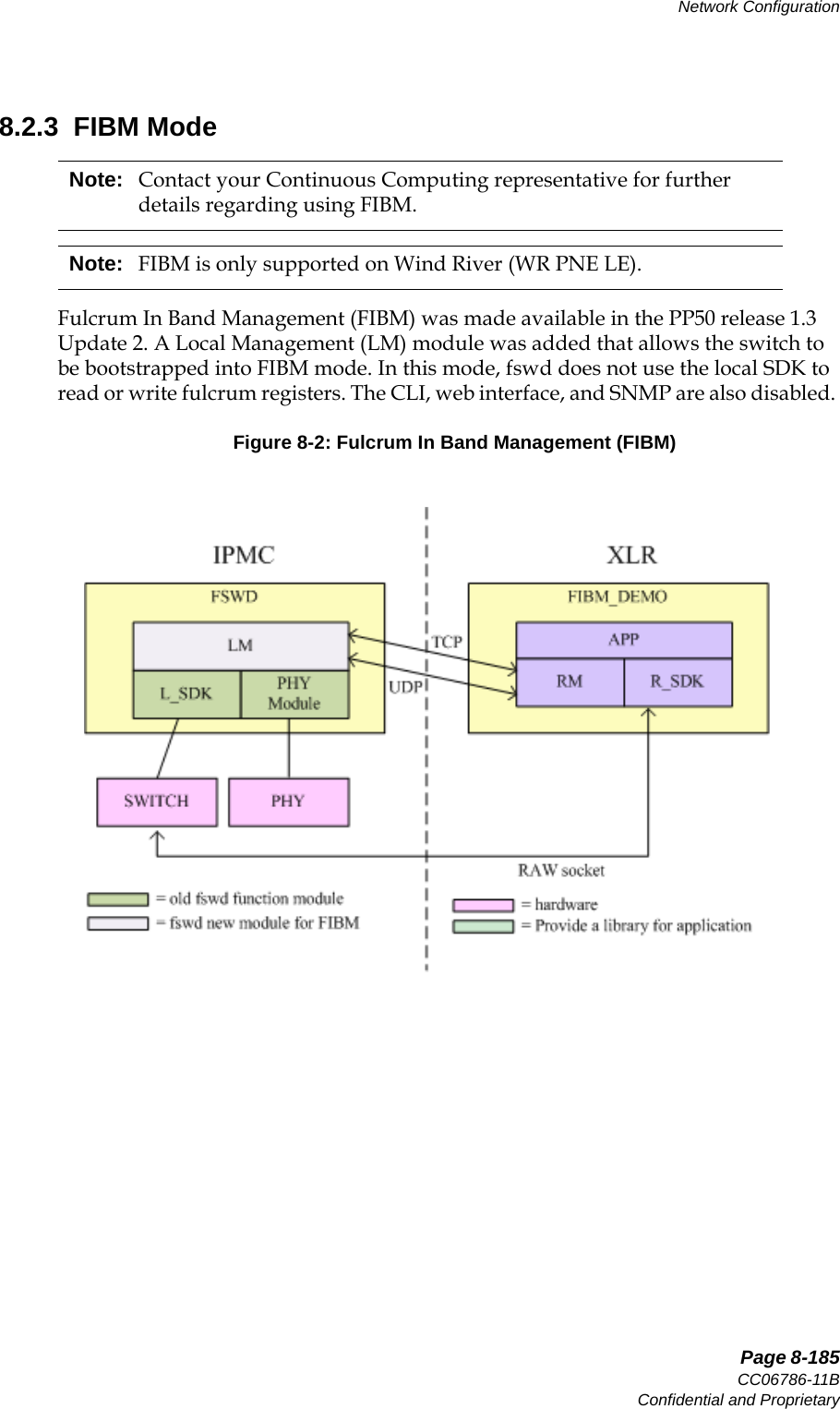
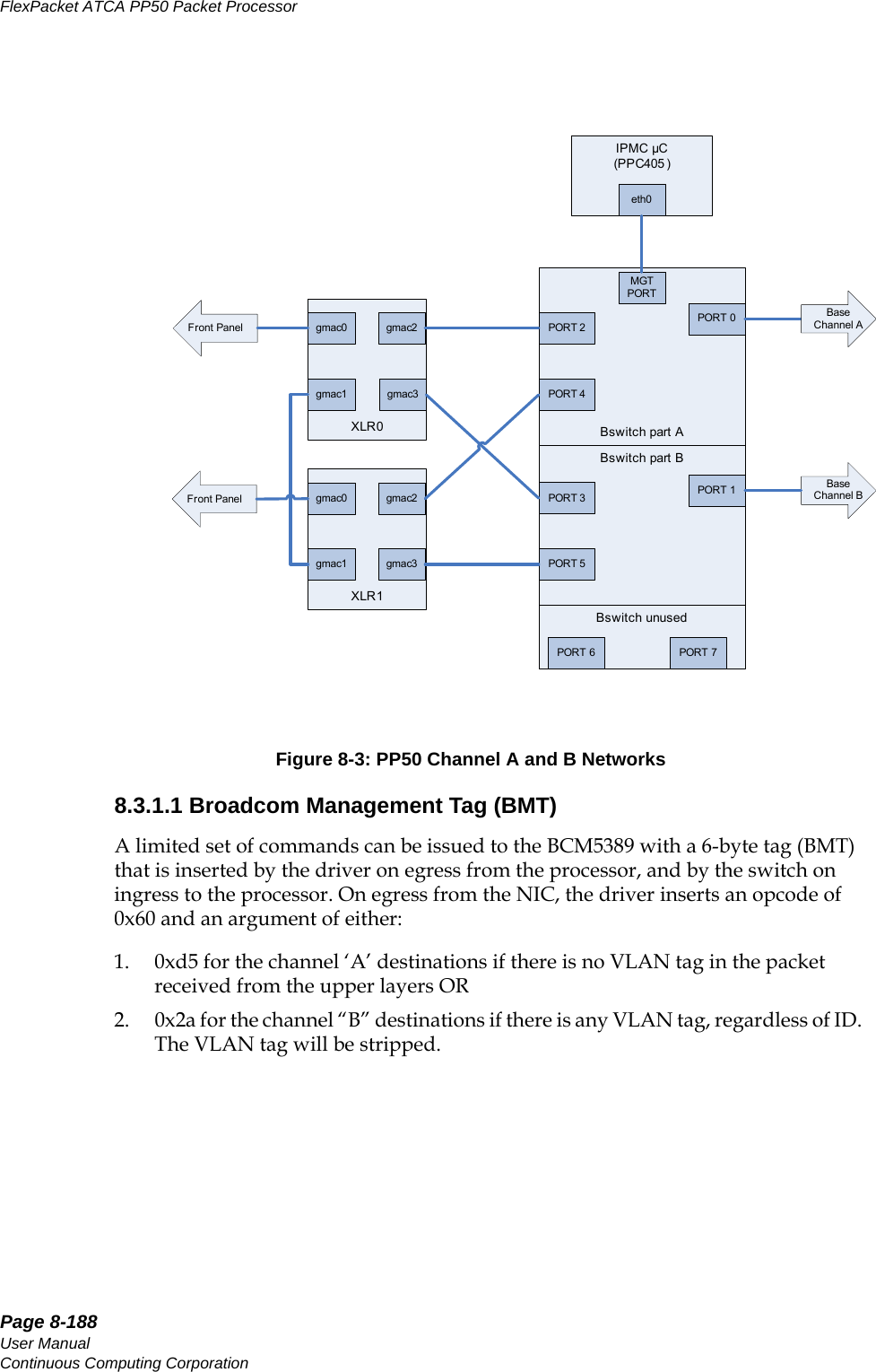
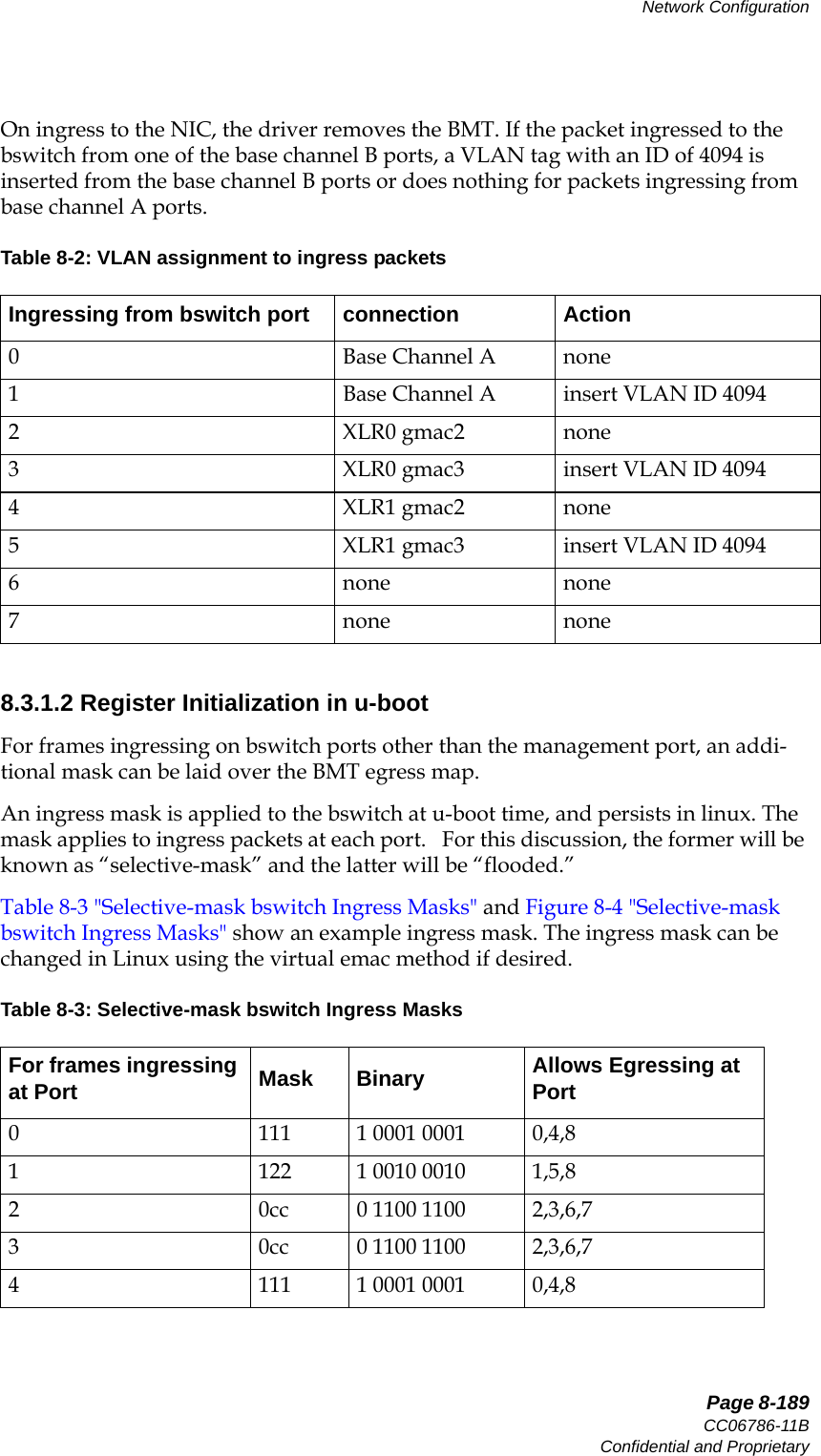
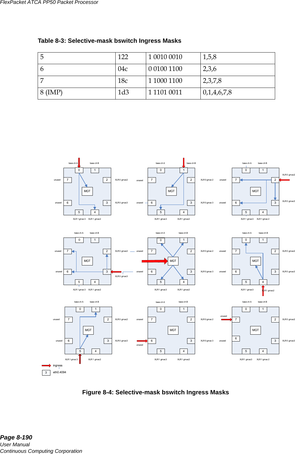
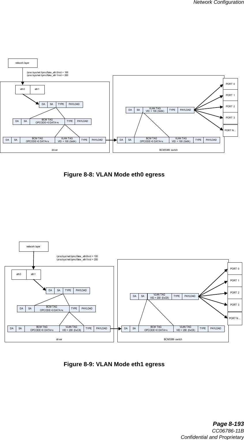
![Page 8-187CC06786-11BConfidential and ProprietaryNetwork Configuration14ABABPreliminary8.3 Base Switch Management and Port Connectivity The base switch lets you add a port specific tag to an incoming packet and multiple VLAN tagging (with no inherent limit other than packet length). These abilities allow the PP50 to work with packets that are already singly or doubly tagged.The base switch supports removing the outermost VLAN tag as the packet egresses from the switch. This allows the VLAN partitioning to occur transparently to the application and end devices, and allows the one physical switch to function as mul-tiple independent virtual switches.Aport can be a member of multiple VLANs and packets exiting the switch can retain the VLAN tag identifying which VLAN the packet belongs to. This mode allows a single physical port to send traffic to multiple destination networks on a packet by packet basis.The Ethernet data path is facilitated through a 10GbE capable switch. The FM2112 contains eight 10GbE interfaces and sixteen 1GbE interfaces.The fabric interface to the AdvancedTCA backplane can be configured as a build time option for 10GbE or for up to 4x 1GbE operation. In 10GbE operation, Ports 7 and 5 are wired to all 4 ports in channels 1 and 2. In four 1GbE operation, Ports 7 and 5 are put in 1GbE mode and make up the ‘A’ ports of the two fabric channels. Switch ports [15 19 13] make up ports [b c d] for channel 1, and likewise switch ports [21 11 9] make up ports [b c d] for Fabric channel 2.8.3.1 Default BehaviorThe linux ethernet driver in the IPMC had originally been modified to enable using the Broadcom BCM5389 switch in a “statically managed” mode. This allowed the processor with a single ethernet NIC to present two virtual broadcast domains (A and B) to the system. A VLAN with ID 4094 was established at startup time, and any entity wishing to send packets to the ‘B’ network needed to use that VLAN. Table 8-1: Virtual Broadcast DomainsNetwork A Network BXLR0 gmac2 XLR0 gmac3XLR1 gmac2 XLR1 gmac3Base Channel A Base Channel B](https://usermanual.wiki/UTStarcom/MSG2000/User-Guide-2403206-Page-185.png)

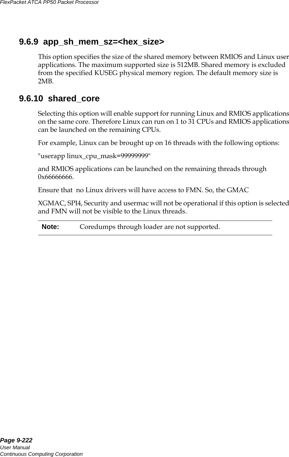
![Page 9-223CC06786-11BConfidential and ProprietaryUsing Wind River Linux on the PP5014ABABPreliminary9.7 Linux Loader ApplicationsThe Linux loader application runs on top of the Linux OS. It allows Linux to be run on threads and provides the userapp command. See Section9.7.1, "userapp" for details about this command.When this "loader" support is enabled, multiple instances of Linux can be run on a configurable number of threads (1 to 31) and various RMIOS applications can be loaded on the remaining threads. This framework supports shared memory between RMIOS applications and Linux user applications. The size of the shared memory is configurable through Linux boot time arguments.The userapp command loads and unloads RMIOS programs from within Linux. The Linux instance running on core one allows the userapp command to load the RMIOS onto the other seven cores and to start. The following Linux Loader applications are available on the PP50. 9.7.1 userapp The userapp command can be used with the following options:9.7.1.1 loadThis option is used to load RMIOS applications. Both KSEG and KUSEG are supported. The following command line options are supported for load:Buddy CPU mask for KUSEG applications. The thread specified in buddy mask are marked are busy and cannot be used for any other application until the master CPU exits Note: The Linux OS, bootloader RMIOS, and Linux loader application being run on a PP50 must all come from the same version of the SDK../userapp load -f <file> -m <mask> [-h]-f <file> : To specify the ELF file to load-m <bitmask> : Mask of CPUs to startNote: Only one bit should be set in bitmasks for KSEG applications. -b <buddy_cpu_mask>](https://usermanual.wiki/UTStarcom/MSG2000/User-Guide-2403206-Page-221.png)
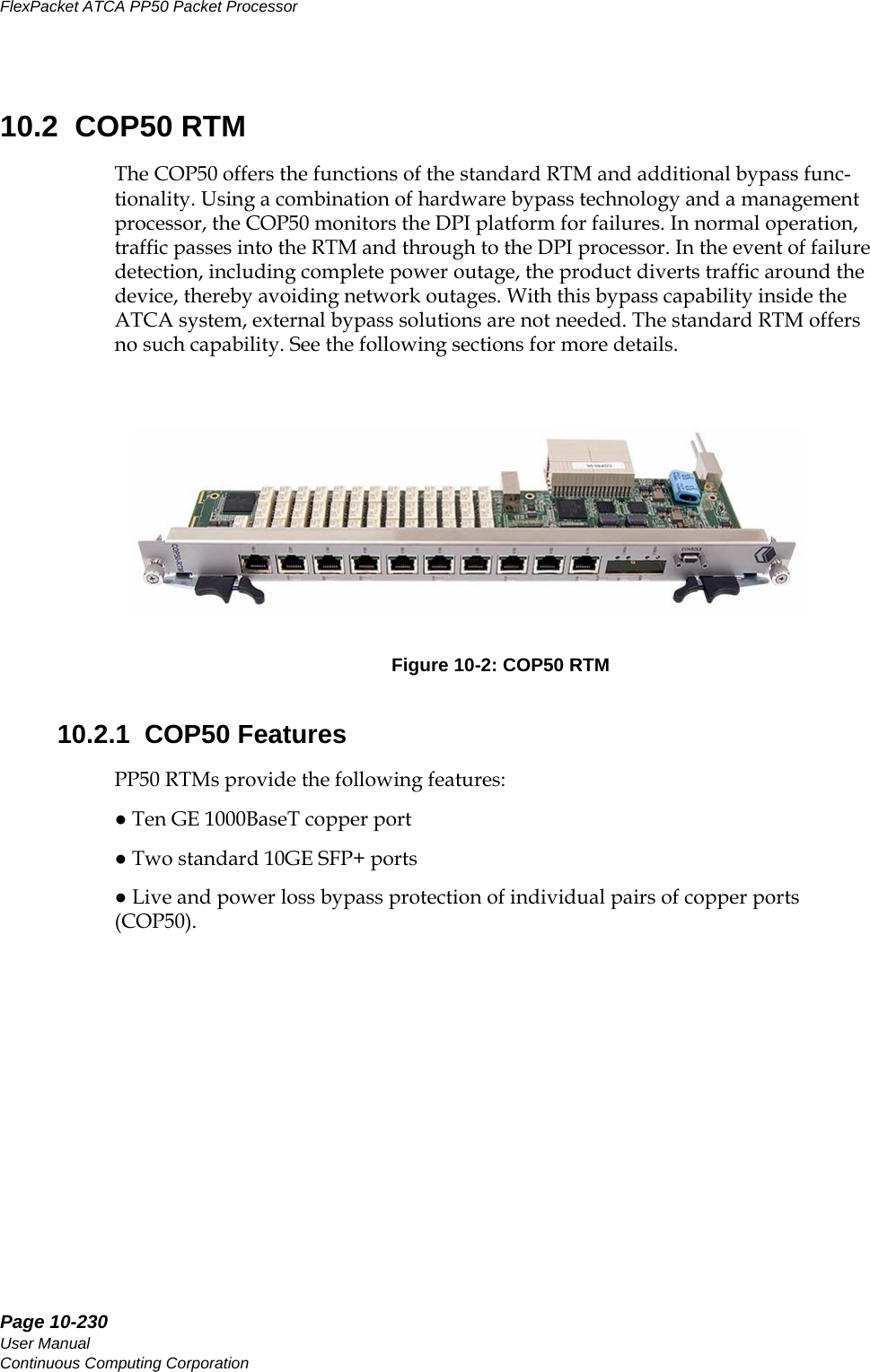
![Page 10-234User ManualContinuous Computing CorporationFlexPacket ATCA PP50 Packet Processor PreliminaryThe block diagram above presents 5 distinct pairs of copper GE ports creating a pro-tected channel where one ingress GE port can be switched to its associated egress GE port in the event of a software or power failure. Relays are used to mechanically connect adjacent ports.Both 10GE SFP+ ports operate in standard mode and do not receive any protection.10.2.3.1 Bypass protectionControl of the bypass protection resides within the front blade IPMC complex. At bootup or by management command, software configures each port-pair to enable protection or not. During normal operation, a daemon running on the IPMC acts as a server to allow management software running somewhere else in the system (on the XLRs or an external blade) to kick the RTM CPLD watchdog at regular interval to confirm its sanity.Upon failure of either watchdog timer or power, the CPLD initiates a protection switch on all port-pairs such provisioned. Relays are simply reset in the bypass position connecting ingress and egress copper port together as a line loopback.10.2.4 COP50 Specifications and Features• All AdvancedTCA components conform to the AdvancedTCA specification: PICMG3.0 R2.0 • The RTM-COP50 RTM is hot swappable.10.2.4.1 General• Ten 1000BaseT gigabit Ethernet ports over RJ45 terminating SerDes lanes from the front blade.• Two 10GE SFP+ ports terminating XAUI lanes across their respective PHYs.• Electrical bypass protection of individual 1000BaseT GE port-pairs [pair of GE ports].10.2.4.2 Mechanical• The COP50 base board may be used as a single wide RTM in accordance with PICMG 3.0.• Dual RJ45 connectors are magnetic free but contain LEDs. • Contains a serial port with RS232 transceiver and microDB9 connector.• RTM back panel • has a metal shield covering RJ45 connectors, relay circuitry and secondary side of magnetics to minimize EMC/EMI interference.10.2.4.3 Power• The power supply supports hot swap.](https://usermanual.wiki/UTStarcom/MSG2000/User-Guide-2403206-Page-232.png)
![Page 10-244User ManualContinuous Computing CorporationFlexPacket ATCA PP50 Packet Processor Preliminary6. Arm the ports by typing “a all”7. Check the RTM LEDs (within 20 seconds) to see proper indications.8. Every 10 seconds or so, type “s all” to strobe the watchdogs and keep the ports in Inline state.9. Check the status with “q”10. Do not send any arm commands for more than 20 seconds. You can then confirm port-pairs 0-2 are in Bypass state by cross-checking LED state, “q” command output, and link state from fswd for the RTM 1G ports.11. Use “Control-] <enter> e <enter>” to exit IPMC telnet.Note: you can also use telnet from any other networked PC by connecting to port 9725 on the PP50 IPMC’s IP address.](https://usermanual.wiki/UTStarcom/MSG2000/User-Guide-2403206-Page-242.png)

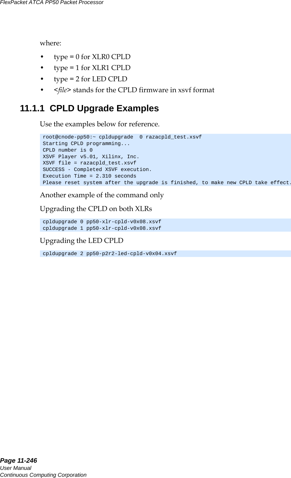
![Page 11-247CC06786-11BConfidential and ProprietaryFirmware Upgrades14ABABPreliminary11.2 XLR bootloader UpgradeThis section describes how to upgrade the XLR0 and XLR1 bootloaders.11.2.1 Get Image File11.2.1.1 Upgrade Boot Flash Via Network1. Assume the new bootloader image file (flash.bin) is located at tftp server 10.4.69.69:/tftpboot/.2. Connect both XLRs' gmac0 to the network via a cable before XLR bootup, then boot the XLR and run the command below on the bootloader's prompt.3. Run command "ifconfig -i gmac0 -a 10.4.69.11 -g 10.4.0.254 -n 255.255.255.0." The outputs will be as follows. 11.2.1.2 Get Bootloader Image File from TFTP Server Run command "tftpc -s 10.4.69.69 -f flash.bin". The output will be as follows.11.2.2 Loading Image FilesThe PP50 offers two methods for upgrading XLR firmware. •Ping-Pong Upgrade Method•Factory Golden Upgrade MethodBoth ensure the system remains operable. The choice is one of customer conve-nience and custom. Set IP address for gmac0PP50-0 $ ifconfig -i gmac0 -a 10.4.69.11 -g 10.4.0.254 -n 255.255.255.0ipaddr: 10.4.69.11gateway: 10.4.0.254netmask: 255.255.255.0PP50-0 $ Starting Network interface "gmac0"PP50-0 $ tftpc -s 10.4.69.69 -f flash.binDownloading [flash.bin].Server IP : 10.4.69.69tftpc stall, check network setupBytes downloaded: 786432tftpc: download done. size = 786432 @ address 0x8c396530PP50-0 $Note: The XLR always copies the bootloader it is running to flash, so there is no problem with upgrading the current active bank.](https://usermanual.wiki/UTStarcom/MSG2000/User-Guide-2403206-Page-245.png)
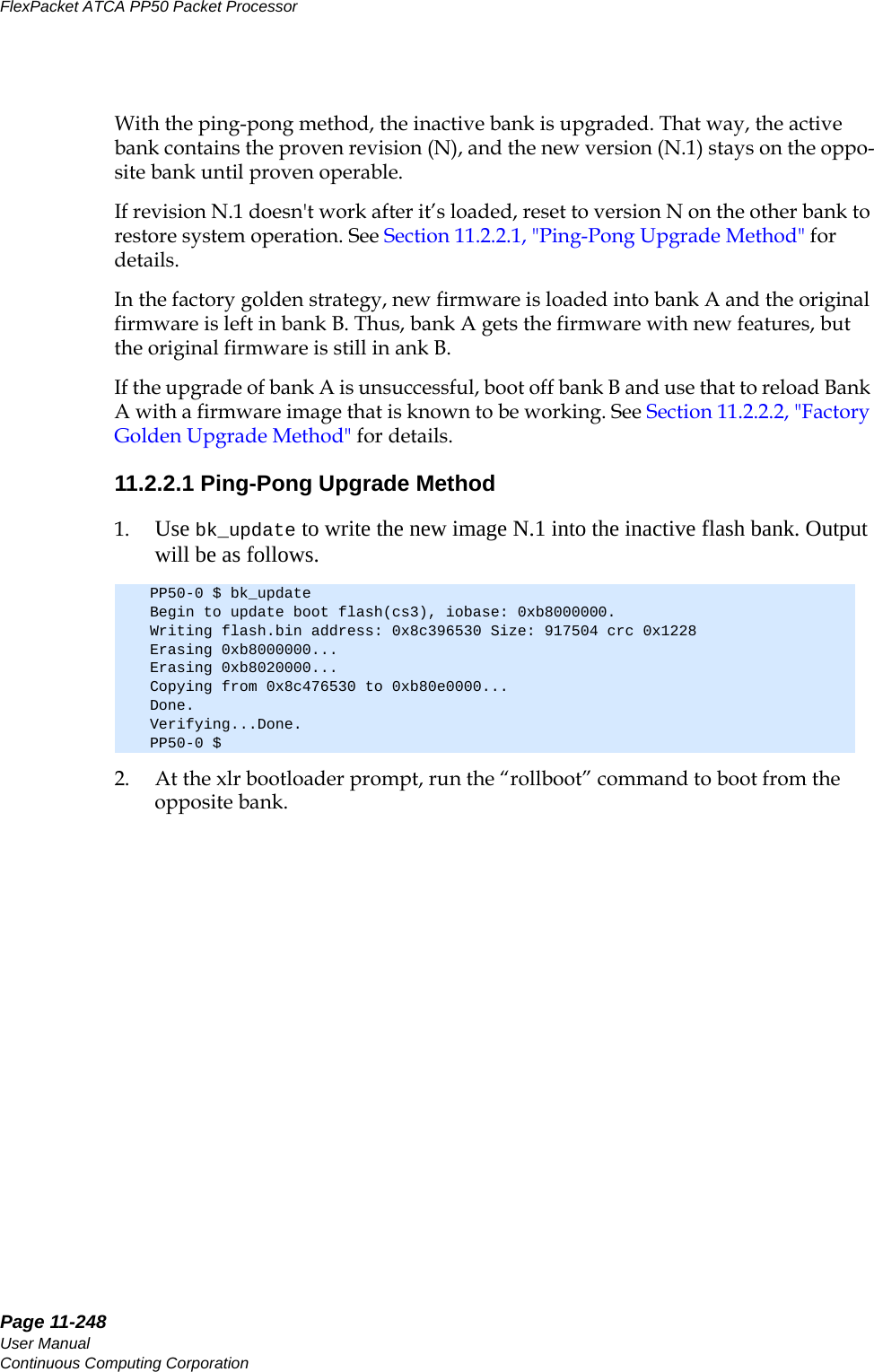
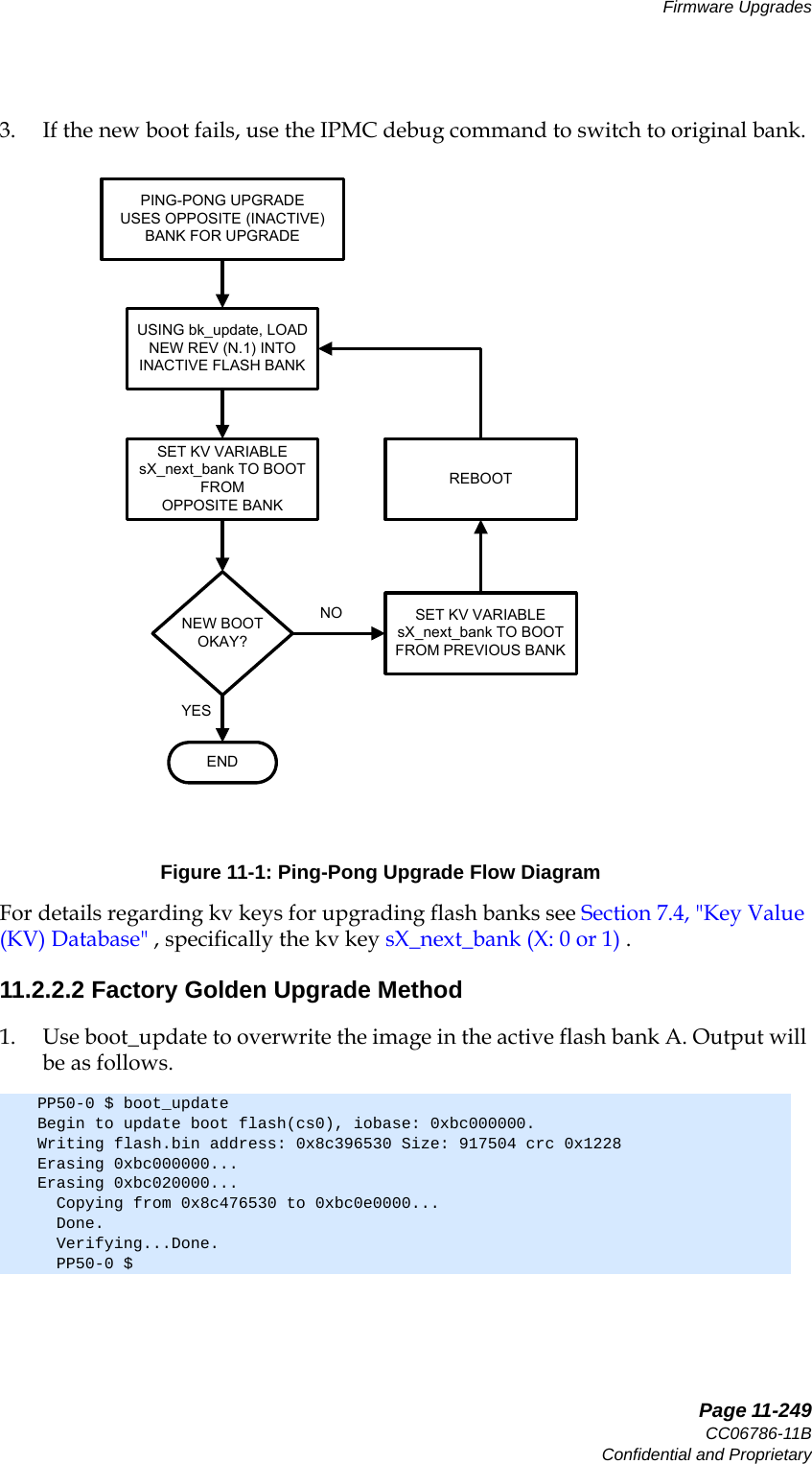
![Page 11-250User ManualContinuous Computing CorporationFlexPacket ATCA PP50 Packet Processor Preliminary2. Reboot without changing boot banks. Output will be as follows.3. If the upgrade fails, use the KV boot bank variable to boot from the Factory Golden image, Bank B.4. Once booted from Bank B, use bk_update to write a correctly working image into the primary flash bank. Output will be as follows.PP50-0 $ reboot---------------------------------------------------------------- System will be rebooted in about 1 seconds... Compiled @ 0x0000000046FBA3AF seconds from epoch Power On reset config = 0x00000000005854EF================================================================ Continuous Computing Bootloader 1.3 [Version: pp50-xlr-v2.1.0b00-rc1] for XLR732 on PP50-P2 Board (type h for help)================================================================ PP50-0 $PP50-0 $ bk_updateBegin to update boot flash(cs3), iobase: 0xb8000000.Writing flash.bin address: 0x8c396530 Size: 917504 crc 0x1228Erasing 0xb8000000...Erasing 0xb8020000...Copying from 0x8c476530 to 0xb80e0000...Done.Verifying...Done.PP50-0 $](https://usermanual.wiki/UTStarcom/MSG2000/User-Guide-2403206-Page-248.png)
![Page 11-257CC06786-11BConfidential and ProprietaryFirmware Upgrades14ABABPreliminary11.4 Linux Bootloader Upgrade ToolUse this tool to upgrade the Linux XLR bootloader.11.4.1 In WR LinuxBelow is example of using the WR Linux upgrade tool.root@10:/root> upgrade -Vupgrade version 1.2root@10:/root> upgrade Usage: upgrade <-a | -s> [options] Options: -? Display this usage -V Display version of this program -a Use active flash for operation -s Use backup flash for operation -b <backup file> Backup flash info to a file -p <program file> Program file to flash -v <program file> Verify flash info with a file for example For bakckup: upgrade -a -b bootloader.bck For program: upgrade -s -p bootloader.bin For verify: upgrade -s -v bootloader.binroot@10:/root> upgrade -a -b bootloader.bckBackup flash physical address 0x1c000000 size 0x200000 to file bootloader.bck... successroot@10:/root> upgrade -s -b bootloader.bcksBackup flash physical address 0x18000000 size 0x200000 to file bootloader.bcks... successroot@10:/root> upgrade -s -p bootloader.bin Erase flash physical address 0x18000000 size 0x120000Program flash physical address 0x18000000 size 0x120000 with filebootloader.binVerify flash physical address 0x18000000 size 0x120000Program flash successfullyroot@10:/root> upgrade -a -p bootloader.binErase flash physical address 0x1c000000 size 0x120000Program flash physical address 0x1c000000 size 0x120000 with filebootloader.binVerify flash physical address 0x1c000000 size 0x120000Program flash successfullyroot@10:/root> upgrade -a -v bootloader.binVerify flash physical address 0x1c000000 size 0x120000 with file bootloader.bin... successroot@10:/root> upgrade -s -v bootloader.binVerify flash physical address 0x18000000 size 0x120000 with file bootloader.bin... successroot@10:/root> upgrade -s -v bootloader.binroot@10:/root> upgrade -s -p ../bootloader.binErase flash physical address 0x18000000 size 0x120000Program flash physical address 0x18000000 size 0x120000 with file../bootloader.binVerify flash physical address 0x18000000 size 0x120000Program flash successfully](https://usermanual.wiki/UTStarcom/MSG2000/User-Guide-2403206-Page-255.png)
![Page 11-258User ManualContinuous Computing CorporationFlexPacket ATCA PP50 Packet Processor Preliminary11.4.2 In RMI LinuxBelow is example of using the RMI Linux upgrade tool.[root@XLR-732 luogr]$ upgrade -?Usage: upgrade <-a | -s> [options] Options: -? Display this usage -V Display version of this program -a Use active flash for operation -s Use backup flash for operation -b <backup file> Backup flash info to a file -p <program file> Program file to flash -v <program file> Verify flash info with a file for example For bakckup: upgrade -a -b bootloader.bck For program: upgrade -s -p bootloader.bin For verify: upgrade -s -v bootloader.bin[root@XLR-732 luogr]$ upgrade -Vupgrade version 1.2[root@XLR-732 luogr]$ upgrade -a -b bootloader.bckBackup flash physical address 0x1c000000 size 0x200000 to file bootloader.bck... success[root@XLR-732 luogr]$ upgrade -s -b bootloader.bcksBackup flash physical address 0x18000000 size 0x200000 to file bootloader.bcks... success[root@XLR-732 luogr]$ upgrade -s -p bootloader.binErase flash physical address 0x18000000 size 0x120000Program flash physical address 0x18000000 size 0x120000 with filebootloader.binVerify flash physical address 0x18000000 size 0x120000Program flash successfully[root@XLR-732 luogr]$ upgrade -a -p bootloader.binErase flash physical address 0x1c000000 size 0x120000Program flash physical address 0x1c000000 size 0x120000 with filebootloader.binVerify flash physical address 0x1c000000 size 0x120000Program flash successfully[root@XLR-732 luogr]$ upgrade -s -v bootloader.binVerify flash physical address 0x18000000 size 0x120000 with file bootloader.bin... success[root@XLR-732 luogr]$ upgrade -a -v bootloader.binVerify flash physical address 0x1c000000 size 0x120000 with file bootloader.bin... success[root@XLR-732 luogr]$ upgrade -v bootloader.binPlease use option <-a | -s> to select the operation flash[root@XLR-732 luogr]$](https://usermanual.wiki/UTStarcom/MSG2000/User-Guide-2403206-Page-256.png)
![Page 12-263CC06786-11BConfidential and ProprietaryDiagnostics and Troubleshooting14ABABPreliminaryUse 'diag [<test1> [<test2>...]]' to get more info.Use 'diag run [<test1> [<test2>...]]' to run tests.2. Enter the test option to get a description about a specific test.diag [<test1> [<test2>...]]:For example:This test verifies the I2C operation.3. Use the run option to run a specified test.diag run [<test1> [<test2> ...]]:For Example:4. Use “diag run” to run all the test itemsSome items need the fpga function, so you need to “run netup” before “diag run”After all the items have finished, the test result summary will be listed as follows:12.2.2 XLR Raw CLI Diagnostic Commands1. At the XLR bootloader prompt, type the diag command to view the available tests. => diag i2ci2c - I2C test => diag run i2c POST i2c PASSEDdiag run: => diag run POST i2c PASSED POST rtc Get RTC s since 1.1.1970: 23338344. POST bcm5389 PASSED POST fm2112 PASSED POST fpga FPGA version :0x8f Board version:0x01 FPGA Magic :0x7e PASSED POST frusel PASSED POST hwaddr HW address 0x48, logic slot 0x8 PASSED POST ne1617 PASSED POST pmc8380 PASSED POST rtm PASSEDPP50-0 $ diag](https://usermanual.wiki/UTStarcom/MSG2000/User-Guide-2403206-Page-261.png)
![Page 12-264User ManualContinuous Computing CorporationFlexPacket ATCA PP50 Packet Processor PreliminaryThe available hardware tests are listed below.Use 'diag [<test1> [<test2>...]]' to get more info.Use 'diag run' to run all test items.Use 'diag run [<test1> [<test2>...]]' to run specified test item.Refer to IPMC diagnostic command examples for usage of related test options.Table 12-2: XLR Raw CLI Diagnostic (Hardware) TestsTest Test Description Durationgphy0 - bcm5482 gmac0 test instantgphy1 - bcm5482 gmac1 test instantgphy2 - bcm5482 gmac2 test instantgphy3 - bcm5482 gmac3 test instantxgphy0 - vsc7280 xgmac0 test instantxgphy1 - vsc7280 xgmac1 test instantcpld - cpld test 1smemshort - short memory test 2sflashlog - part flash test 5-10sflashall - full flash test 20-25mmemlong - long memory test 4-5 hourspsram - psram test 45-75spcmcia - pcmcia test 1-2stcam - tcam register test variespft - pseudo fault test variessipl - uart 1 sipl channel test 1s](https://usermanual.wiki/UTStarcom/MSG2000/User-Guide-2403206-Page-262.png)
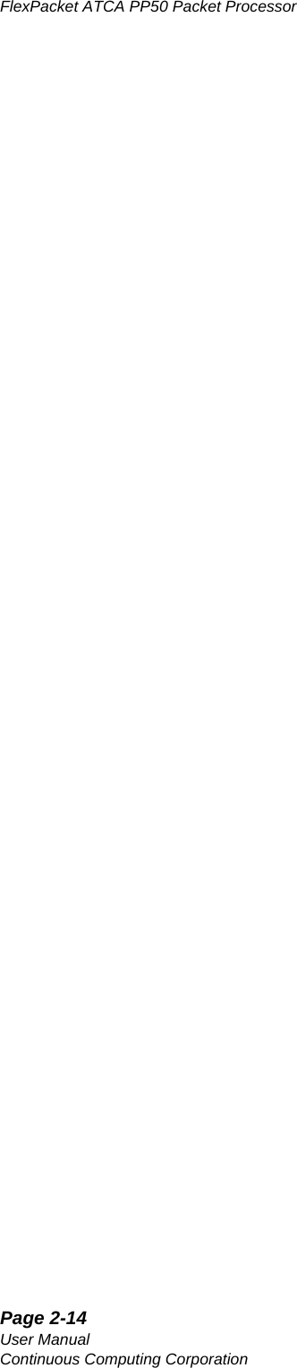
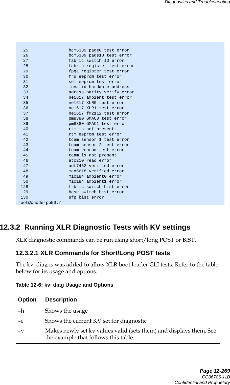
![Page 12-266User ManualContinuous Computing CorporationFlexPacket ATCA PP50 Packet Processor Preliminaryset key s0_test_mask as “1100xxxx000010xxxxxxxxxxxxxxxxxx”where: • 0 disables the test• 1 enables the test• x means the test is invalid in this contextTable 12-5: Diagnostic types and test mask string assignment12.3.1 Running IPMC Diagnostic tests with KV settings12.3.1.1 IPMC U-boot command for short/long POST testsRefer to the commands below to run related short/long POST items which are masked by test mask key string. It is similar to the XLR kv_diag command example.=> help kv_diagkv_diag [ -l | --list ] list bootmode and POST test items by kv "cn_test_mask" and "cn_bootmode"kv_diag [ -e | --execute ] run POST test items by kv"cn_test_mask" and "cn_bootmode"kv_diag [ -r | --result ] show latest POST test resultkv_diag [ -n | --no ] show POST error code and related error string0 1 2 3 4 5 6 7 8 9 10 11 12 13 14 15 16 17 18 19 20 21 22 23 24 25 26 27 28 29 30 31Post T ypeNorm al, De faul tpost_onlybist_onlypost_bistBlank cell indicates test is not run. Note: Short Post Items are always run, even when the boot mode is not set.BISTTest NumberLong PostShort Post Items](https://usermanual.wiki/UTStarcom/MSG2000/User-Guide-2403206-Page-264.png)
![Page 12-267CC06786-11BConfidential and ProprietaryDiagnostics and Troubleshooting14ABABPreliminary12.3.1.2 IPMC Linux utility for POST/BIST tests1. The utility ux_diag is also located in the rootfs folder “/usr/bin/”, refer to the usage below for help.Note in the text above XX = (cn, s0, s1)cn means IPMCs0 means PAYLOAD0s1 means PAYLOAD12. Run command “ux_diag –l cn” to list all available test items for the IPMCroot@cnode-pp50:/etc/cpld ux_diagusage: ux_diag [-u|--update] [cn|s0|s1]usage: ux_diag [-l|--list] [cn|s0|s1]usage: ux_diag [-d|--dump] [cn|s0|s1]usage: ux_diag [-n|--no] [cn|s0|s1]usage: ux_diag [-h|--help] -u update diagnosis configuration using /etc/diag/XX_diag.cfg -l list all available test items and test states configuration -d dump the test result and create /var/log/diag/XX_diag.dump -n list current diagnosis test error number and err string -h for helproot@cnode-pp50:/ ux_diag -l cn IPMC bootmode=normal===========================================================[TEST_STATE] [MASK_POS] [TEST_TYPE] [TEST_CASE] [TEST_TIME] n 0 short post i2c <= 1 sec n 1 short post shortmem <= 15 sec n 8 long post rtc <= 35 sec n 9 long post memory <= 40 sec n 10 long post nand <= 30 sec n 11 long post bcm5389 <= 1 sec n 12 long post fswitch <= 2 sec n 13 long post fpga <= 1 sec n 14 long post frusel <= 1 sec n 15 long post hwaddr <= 1 sec n 16 long post ne1617 <= 1 sec n 17 long post pmc8380 <= 3 sec n 18 long post atc210 <= 2 sec n 19 long post rtm <= 2 sec n 20 long post tcam <= 2 sec n 24 bist sfp <= 90 sec n 25 bist fabricswitch <= 16 min n 26 bist baseswitch <= 10 secroot@cnode-pp50:/](https://usermanual.wiki/UTStarcom/MSG2000/User-Guide-2403206-Page-265.png)
![Page 12-268User ManualContinuous Computing CorporationFlexPacket ATCA PP50 Packet Processor Preliminary3. Run command “ux_diag –d cn” to dump test result4. Run command “ux_diag –n cn” to list all related test result code description.root@cnode-pp50:/ ux_diag -d cn IPMC Diagnostic Test Result===============================================================================[MASK_POS] [TEST_TYPE] [TEST_CASE] [TEST_RESULT] [ERROR_CODE] [ERROR_STRING] 0 short post i2c passed 0 test passed 1 short post shortmem passed 0 test passedBegin to generate cn_diag.dump.Generate cn_diag.dump OK!root@cnode-pp50:/Note: If some test items fail, you can get more details from the log file /var/log/diag/cn_diag.dump.root@cnode-pp50:/ ux_diag -n cnIPMC Diagnosis Error Codes List==============================[code] [description] 0 test passed 1 not test 2 invalid test item 3 not response from i2c address 4 date line test error 5 address line test error 6 verify 0x00000000 error 7 verify 0xffffffff error 8 verify 0x55555555 error 9 verify 0xaaaaaaaa error 10 verify 1 shift error 11 verify address self error 12 verify address reverse error 13 verify address peak poke error 14 verify address bit fade error 15 a new second timeout 16 invalid second duration counts 17 month boundary test error 18 read old data error 19 erase old data error 20 write test data error 21 read test data error 22 verify test data error 23 erase test data error 24 restore old data error](https://usermanual.wiki/UTStarcom/MSG2000/User-Guide-2403206-Page-266.png)
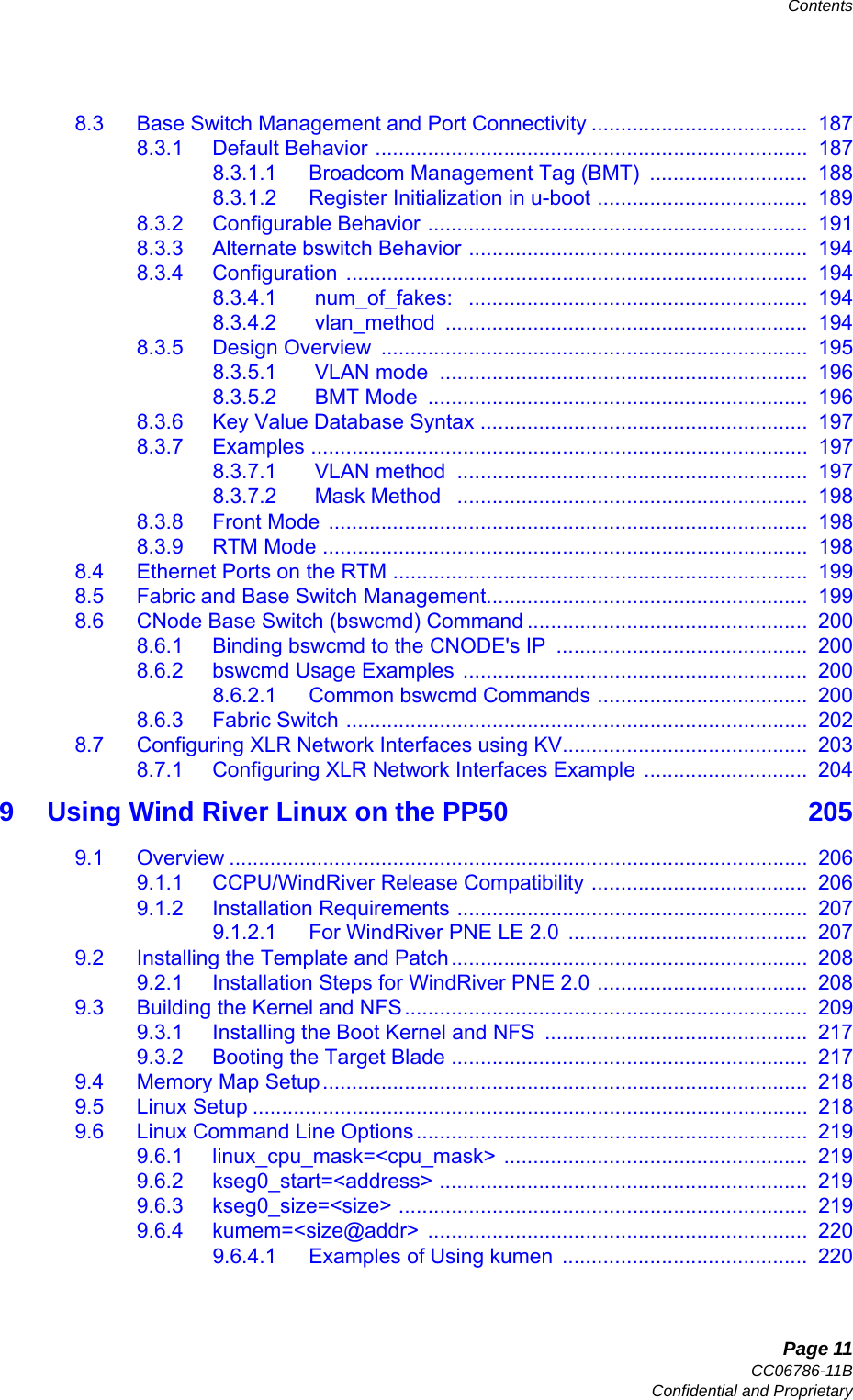
![Page 12-270User ManualContinuous Computing CorporationFlexPacket ATCA PP50 Packet Processor PreliminaryBelow is an example of how to run the short POST diagnostics on bcm5482 gmac0, bcm5482 gmac1, or bcm5482 gmac2 in the XLR boot loader CLI:a. From the XLR boot loader CLI, set the following KV keys:b. Run command “kv_diag –v” to make the key valid.c. Run command “kv_diag –c” to ensure the test cases were executed.d. Run command “kv_diag –e” to execute. See the output below.e. Run command “kv_diag –r” to show test result. See the output below.–l Lists the available POST items in XLR boot loader–e Executes the diagnostic test items currently set in the KV database–r Shows the latest diagnostic test result–n Shows the diagnostic test error codePP50-0 $ kv s0_bootmode normalPP50-0 $ kv s0_test_mask 11100000000000000000000000000000PP50-0 $ kv_diag -vkey s0_test_mask value = "11100000000000000000000000000000"PP50-0 $PP50-0 $ kv_diag -cDiagnostic boot mode is set as: s0_bootmode = "normal"Diagnostic test mask is set as: s0_test_mask = "11100000000000000000000000000000"PP50-0 $ kv_diag -eBCM5482 gmac0 aceess successBCM5482 gmac1 aceess successBCM5482 gmac2 aceess successLong post running in 0 units. Press any key to halt... POST Diagnostic Test Result===========================================================[TEST_CASE] [MASK_POS] [ERROR_CODE] [TEST_RESULT] gphy0 0 0 Pass gphy1 1 0 Pass gphy2 2 0 PassPP50-0 $PP50-0 $ kv_diag -r POST Diagnostic Test Result===========================================================[TEST_CASE] [MASK_POS] [ERROR_CODE] [TEST_RESULT] gphy0 0 0 Pass gphy1 1 0 Pass gphy2 2 0 PassTable 12-6: kv_diag Usage and Options](https://usermanual.wiki/UTStarcom/MSG2000/User-Guide-2403206-Page-268.png)
![Page 12-271CC06786-11BConfidential and ProprietaryDiagnostics and Troubleshooting14ABABPreliminary12.3.2.2 XLR RMI Linux Utility for POST/BIST Tests1. The ux_diag utility in RMI Linux RAM FS /usr/bin/ for XLRs provides the tests described below:2. Run “ux_diag -l s0” to list all available test items for XLR0 as shown below.[root@Stn000116 jwu]$ ./ux_diag -husage: ux_diag [-u|--update] [cn|s0|s1]usage: ux_diag [-l|--list] [cn|s0|s1]usage: ux_diag [-d|--dump] [cn|s0|s1]usage: ux_diag [-n|--no] [cn|s0|s1]usage: ux_diag [-v]usage: ux_diag [-h] -u update diagnosis configuration using /etc/diag/XX_diag.cfg -l list all available test items and test states configuration -d dump the test result and create /var/log/XX_diag.dump -n list current diagnosis test error number and err string -v display version -h for help [root@localhost ~]$ ux_diag -l s0 PAYLOAD0 bootmode=normal==========================================================================[TEST_STATE] [MASK_POS] [TEST_TYPE] [TEST_CASE] [TEST_TIME] n 0 short post bcm5482gmac0 <= 1 sec n 1 short post bcm5482gmac1 <= 1 sec n 2 short post bcm5482gmac2 <= 1 sec n 3 short post bcm5482gmac3 <= 1 sec n 4 short post vsc7280xgmac0 <= 1 sec n 5 short post vsc7280xgmac1 <= 1 sec n 6 short post cpld <= 2 sec n 7 short post shortmem <= 2 min n 8 long post shortflash <= 200 sec n 9 long post fullflash <= 7 min n 10 long post fullmem <= hours n 11 long post psram <= 50 sec n 12 long post pcmcia <= 1 sec n 13 long post tcamreg <= 1 sec n 14 long post pseudofault <= 1 sec n 15 long post uart1test <= 2 sec n 24 bist tcamentry <= 15 sec n 25 bist GEtest <= 90 sec n 26 bist XGEtest <= 45 sec[root@localhost ~]$Note: The tcamentry test (test 24 above) with MASK_POS 24 will be skipped on XLR1 even if it is masked, it can only be executed on XLR0.](https://usermanual.wiki/UTStarcom/MSG2000/User-Guide-2403206-Page-269.png)
![Page 12-273CC06786-11BConfidential and ProprietaryDiagnostics and Troubleshooting14ABABPreliminary3. Run command “ux_diag –d s0” to dump the test resultb. tcamentry test: this BIST item includes following subtest cases:1: 72 bit entry test2: 144, 288 and 576 entry test3: TCAM register access test 4: TCAM database read and write5: Longest prefix match If all the subtests pass the test passes.c. GE test: Tests all four XLR GE ports (eth0 through eth3), if any one GE port fails the test fails.d. : tests both XLR 10GE ports (eth4, eth5), if either fails the test fails.[root@localhost ~]$ ux_diag -d s0 PAYLOAD0 Diagnostic Test Result=============================================================================[MASK_POS][TEST_TYPE][TEST_CASE][TEST_RESULT][ERROR_CODE] [ERROR_STRING]0 short post bcm5482gmac0 passed 0 test ok.1 short post bcm5482gmac1 passed 0 test ok.2 short post bcm5482gmac2 passed 0 test ok.3 short post bcm5482gmac3 passed 0 test ok.4 short post vsc7280xgmac0 passed 0 test ok.5 short post vsc7280xgmac1 passed 0 test ok.6 short post cpld passed 0 test ok.7 short post shortmem passed 0 test ok.Begin to generate s0_diag.dump.Generate s0_diag.dump OK![root@localhost ~]$Note: More details about the test can be found in the log file /var/log/diag/s0_diag.dump.](https://usermanual.wiki/UTStarcom/MSG2000/User-Guide-2403206-Page-271.png)
![Page 12-274User ManualContinuous Computing CorporationFlexPacket ATCA PP50 Packet Processor Preliminary4. Run command “ux_diag –n s0” to display all related test result code descriptions:[root@localhost /]$ ux_diag -n s0PAYLOAD0 Diagnosis Error Code List===================================[code] [description]0 test ok.1 not tested.2 invalid test item.3 test failed with illegal parameters.4 SIPL communication error.5 memory allocated error.6 unable to find the test device.7 unable to read phy id register.8 unrecognized phy.9 write/read register error.10 unkown memory test type error.11 memory walk one test error.12 memory walk zero test error.13 memory write own addr test error.14 memory write unique addr test error.15 memory with setting a 8 bit "moving inversions" algorithm as pattern test error.16 memory with setting a 32 bit "moving inversions" algorithm as pattern test error.17 memory with setting modulo X access pattern test error.18 memory bit fade test error.19 flash erase operation error.20 flash write operation error.21 flash verify error.22 psram addr space test_1 error.23 psram addr space test_2 error.24 psram data line test_1 error.25 psram data line test_2 error.26 psram addr line test error.27 psram access by byte test error.28 psram access by word test error.29 pcmcia detect bad compactflash card error.30 tcam access register error.127 pseudo fault test error.128 TCAM bist error.129 GE port bist error.130 XGE port bist error.[root@localhost /]$](https://usermanual.wiki/UTStarcom/MSG2000/User-Guide-2403206-Page-272.png)
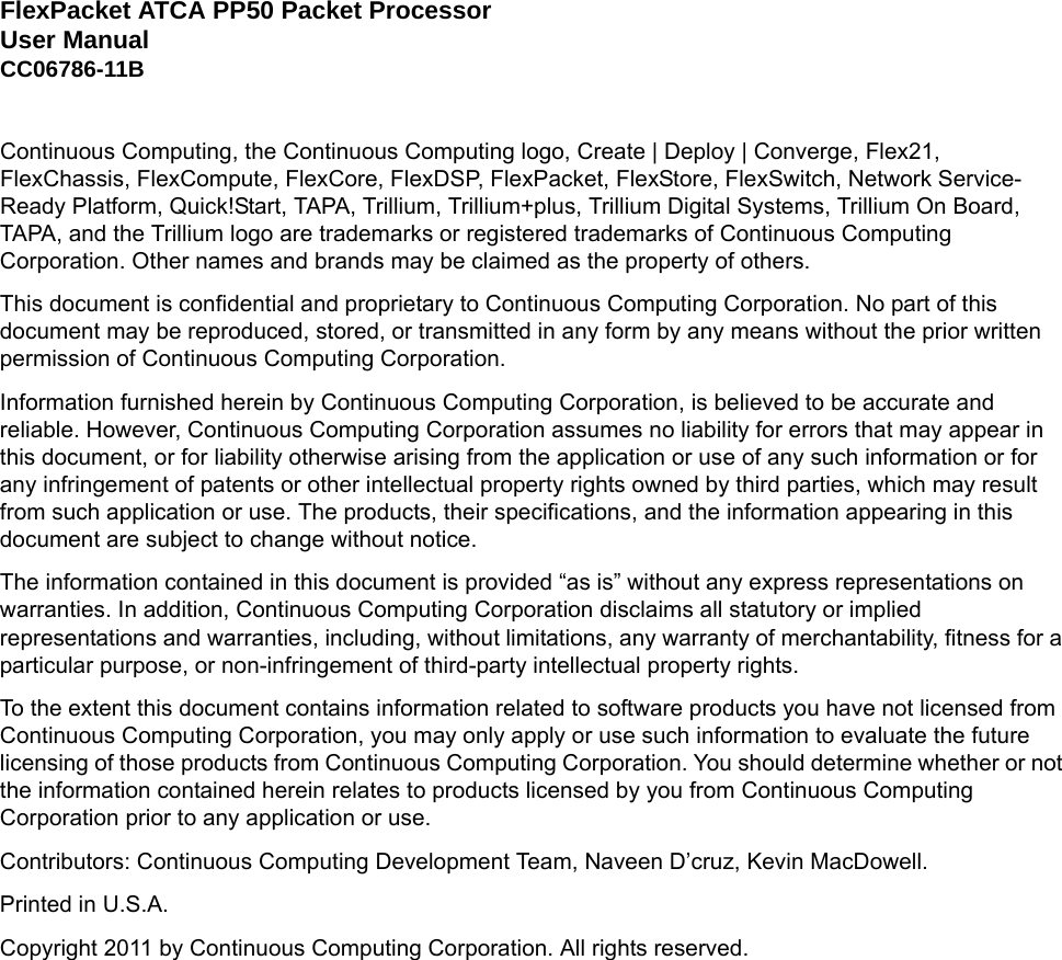
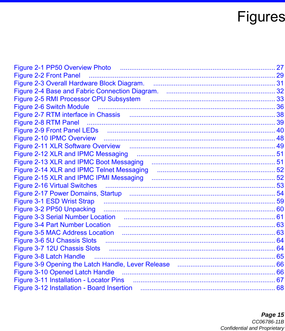
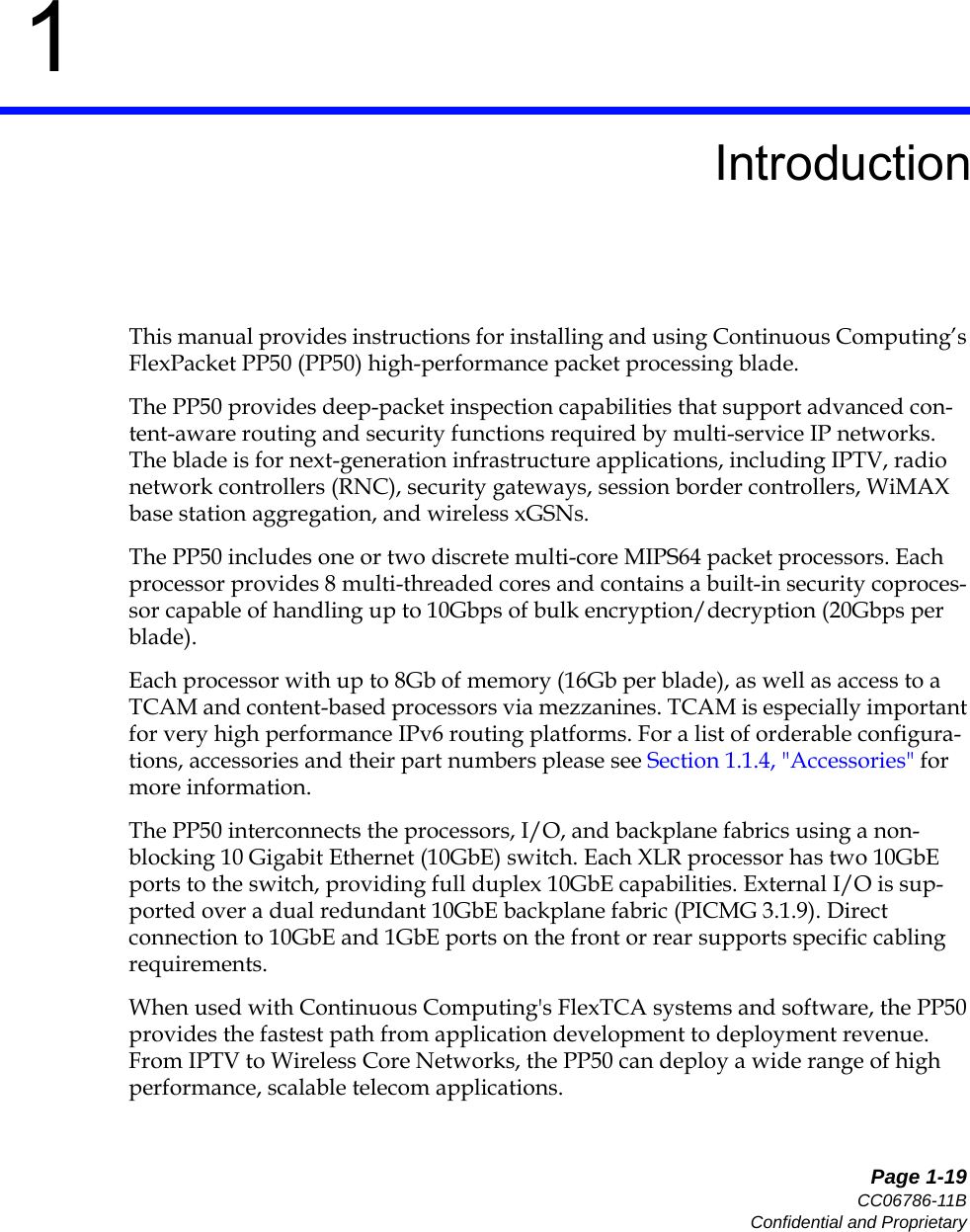
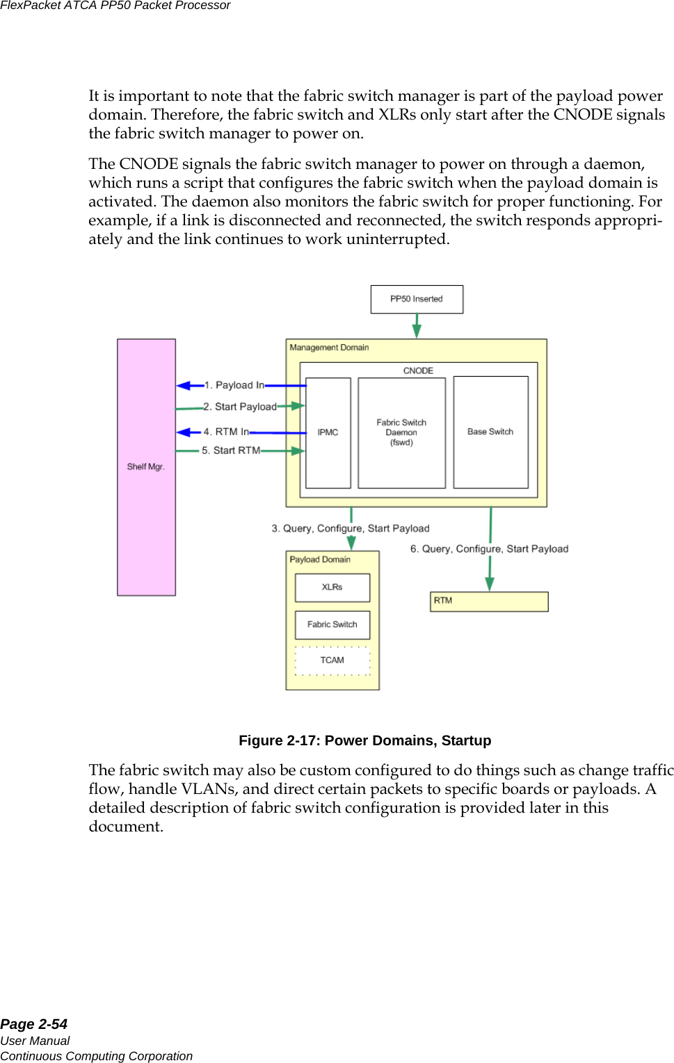
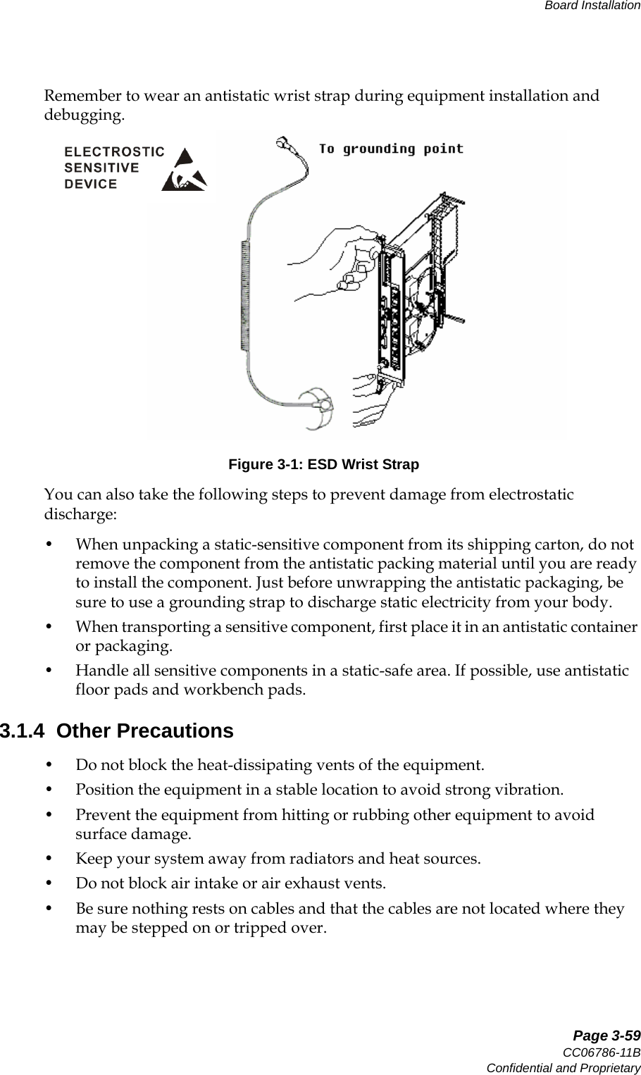
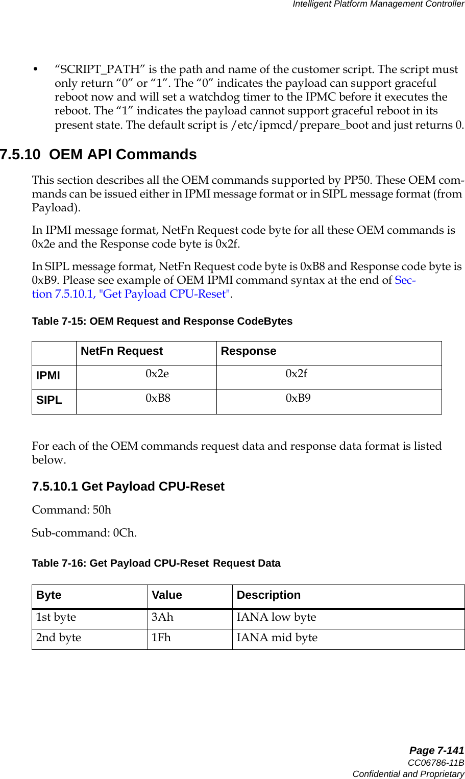
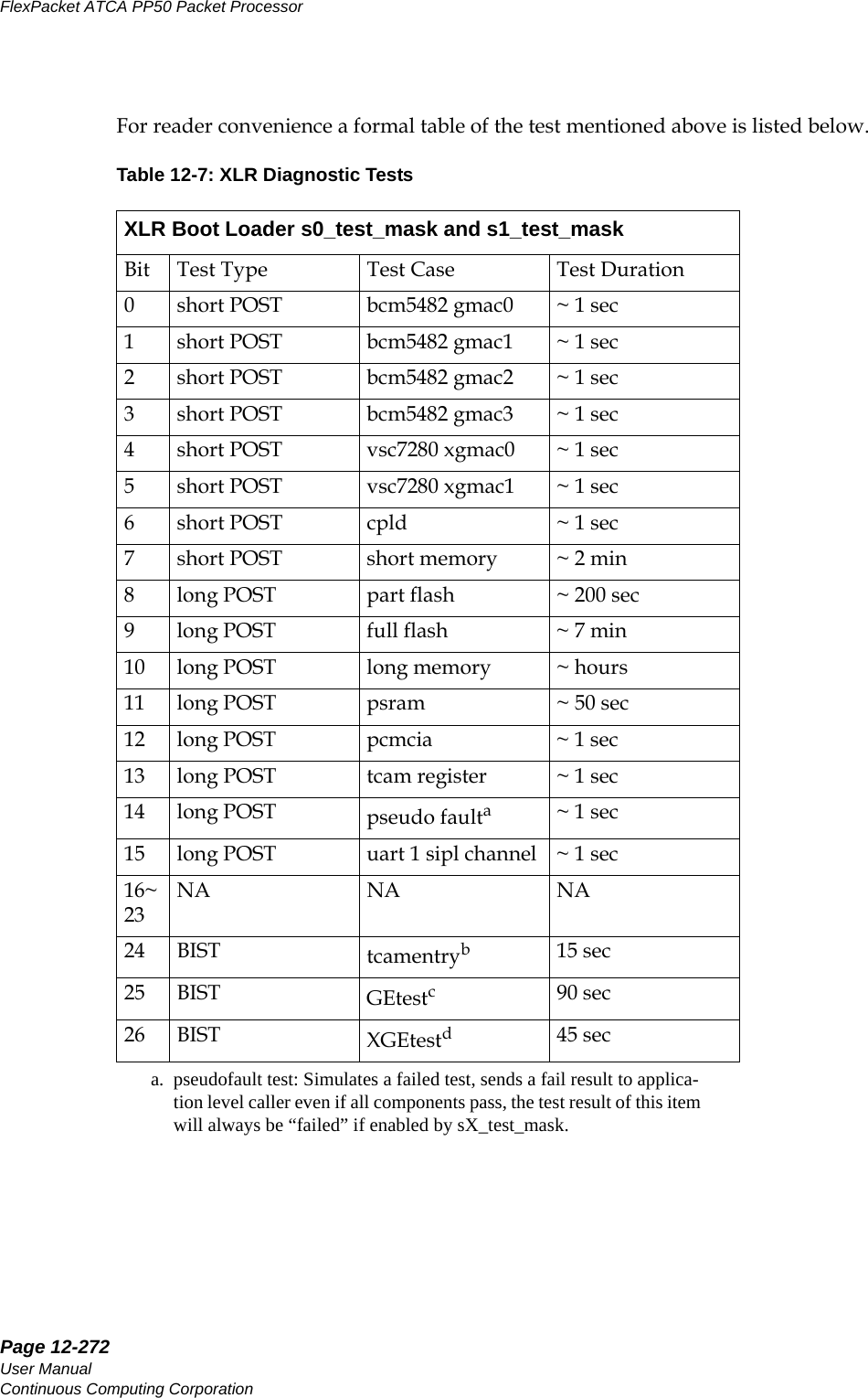
![Page 12-276User ManualContinuous Computing CorporationFlexPacket ATCA PP50 Packet Processor PreliminaryBelow are examples of how the parameters may be set.0 0x82 0x0b long 0 0x82 0x1b off 1 0x82 0x0b short 1 0x82 0x1b off12.5 Determining Board BuildDetermine a board’s build configuration by watching the console output during CNode boot as shown below. Loading FPGA Device 0...........................................Done.FPGA[0] Magic 0x7e BoardID 0x0, Revision 0x93FPGA[0] test startFPGA[0] test passedTable 12-8: Determining Board Build by Revision NumberBoard RevisionPCB XLR Switch Power BrickP2 P2R2 P3 Commer-cial Industrial FM2112 FM3112 LImited Feature FullFeature00 √√ √ √01 √√ √ √02 √√√ √aa. Some early prototypes revision 02 have a non-full feature power brick.03 √√√ √20 √√ √ √21 √√ √ √22 √√√√23 √√ √ √](https://usermanual.wiki/UTStarcom/MSG2000/User-Guide-2403206-Page-274.png)