Ubinetics GM401 Dual band module, EGSM900, GSM1900 with MS8GPRS User Manual Reference
Ubinetics Dual band module, EGSM900, GSM1900 with MS8GPRS Reference
UserManual.wiki
>
Ubinetics
>
GM401 User Manual
>
User manual
Contents
1.
User manual
2.
Revised Safety Guide
3.
Intended use letter
4.
Reference Manual
User manual
Navigation menu
Upload a User Manual
Namespaces
Wiki Guide
HTML
PDF
Info
Views
User Manual
Discussion / Help
Navigation
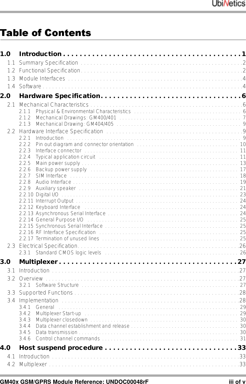
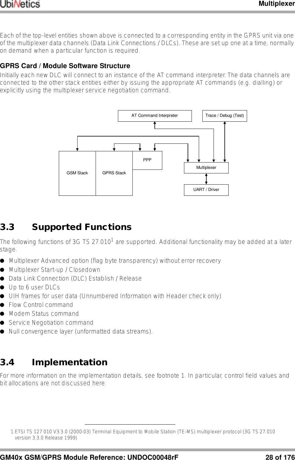
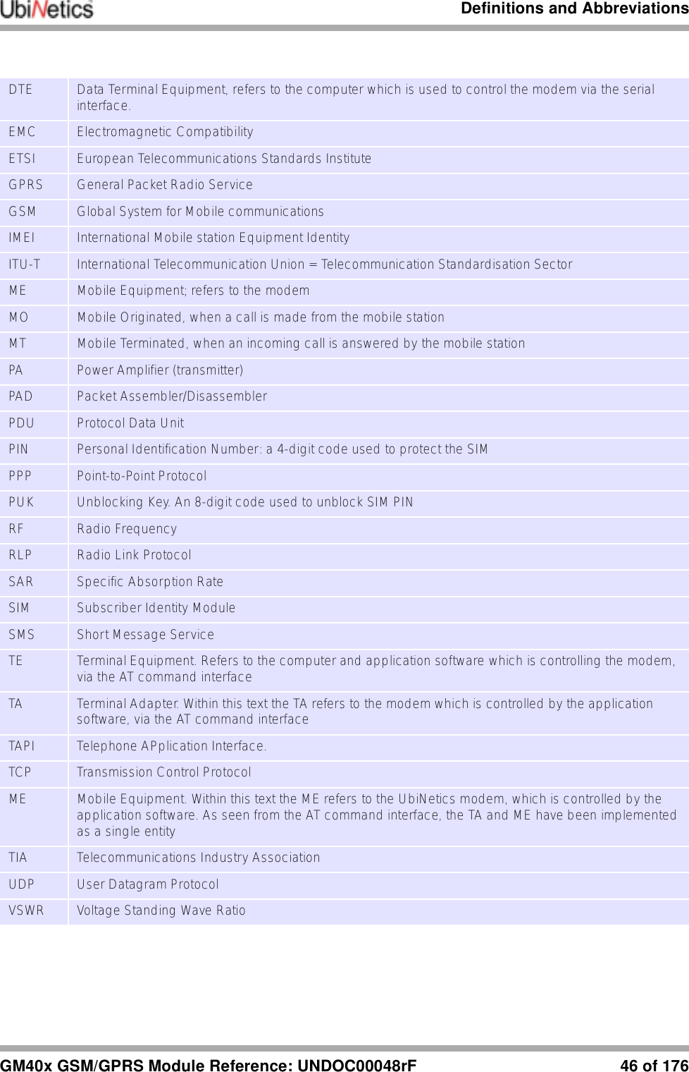
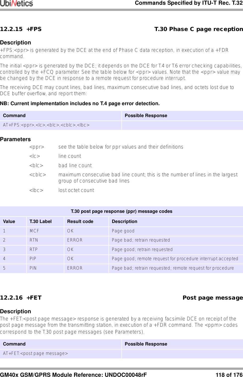
![Definitions and Abbreviations45 of 176 GM40x GSM/GPRS Module Reference: UNDOC00048rF7.0 Definitions and AbbreviationsThis section contains a list of common definitions and abbreviations used in this document.7.0.1 Definitions7.0.2 Syntactical DefinitionsThe following syntactical definitions are used in this document:7.0.3 AbbreviationsThe following abbreviations are used in this document:Off-line Command State The modem enters this state after power up i.e. the modem is not in a data call (off-line) and ready to accept AT commands.On-line Data State The modem will change from off-line command state to on-line data state after successfully setting up a data call. This allows the mobile station to exchange data with the remote station.On-line Command State To change from on-line data state to on-line command state the DTE sends the escape sequence +++. This allows AT commands to be sent to the modem whilst still retaining the data connection to the remote station. The command ATH will end the data call and ATO will return to on-line data state. Remote Station This is the term given to describe the equipment or modem at the other end of the link, when making a mobile originated or mobile terminated call.Mobile Station Throughout this document this term refers to the UbiNetics modem.Mobile Originated (MO) This means a voice call, data call or SMS has initiated by the modem.Mobile Terminated (MT) This means a voice call, data call or SMS has been received by the modem.<cr> Carriage Return character.<lf> Line Feed character.<...> a sub-parameter enclosed within angle brackets, is a syntactical element. The brackets themselves do not appear in the command line.[...] Optional sub-parameter, is enclosed within square brackets. This indicates the element may or may not be present within a result code or can be omitted from the command string. The square brackets themselves do not appear in the command line.underline Indicates a default setting of a sub-parameter value after a factory reset.AT ATtention, used to start a command lineCBM Cell Broadcast MessageCCITT Consultative Committee on International Telegraphy and Telephony DCE Data Connection Equipment, refers to the modem which is controlled by the computer and application software. Also see TA](https://usermanual.wiki/Ubinetics/GM401.User-manual/User-Guide-233185-Page-50.png)
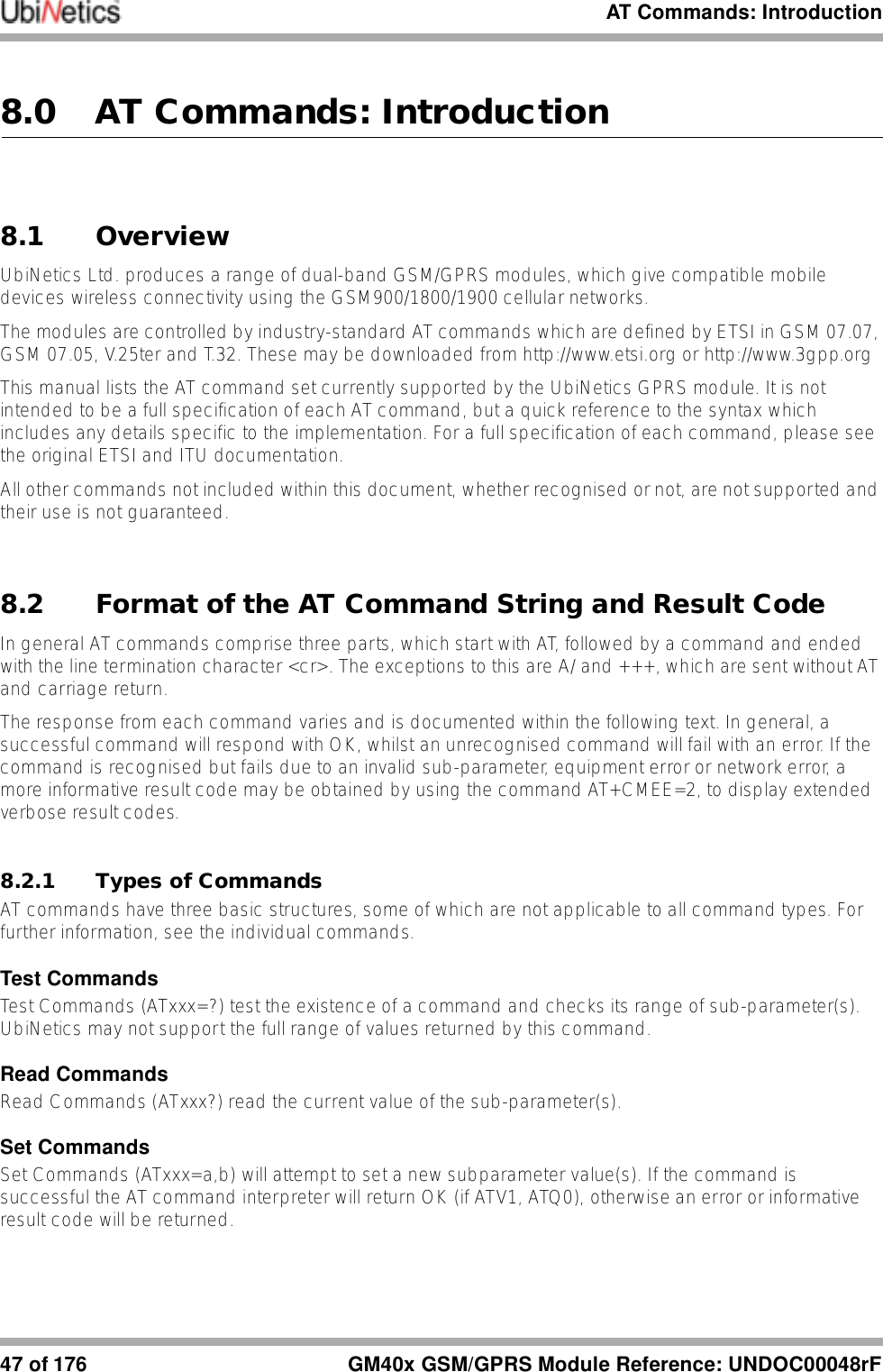
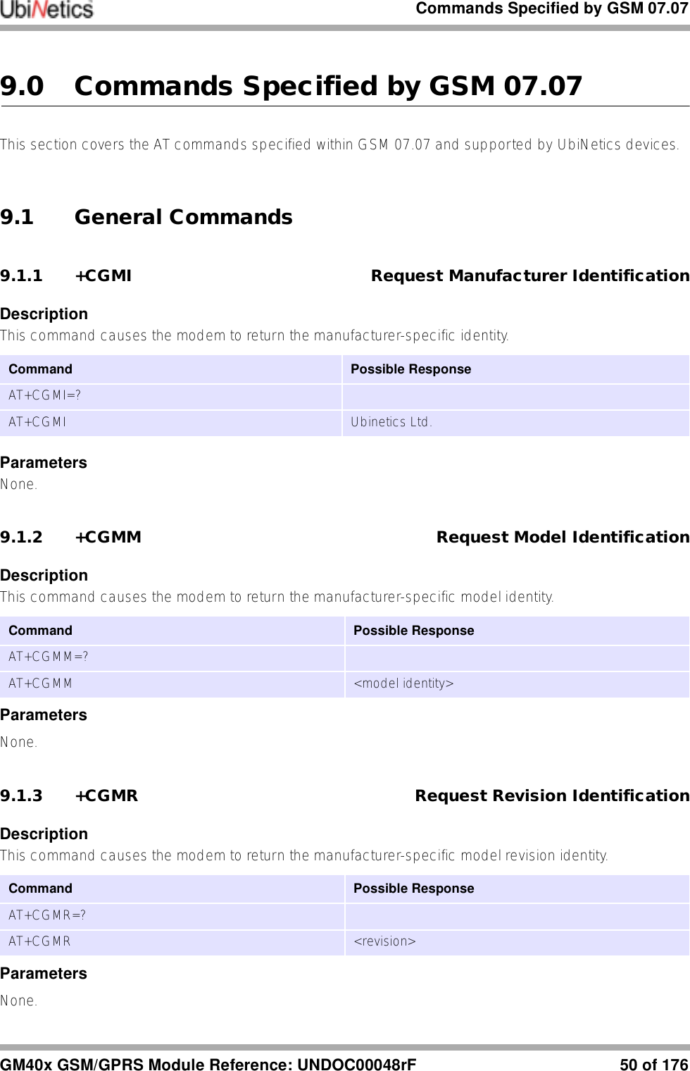
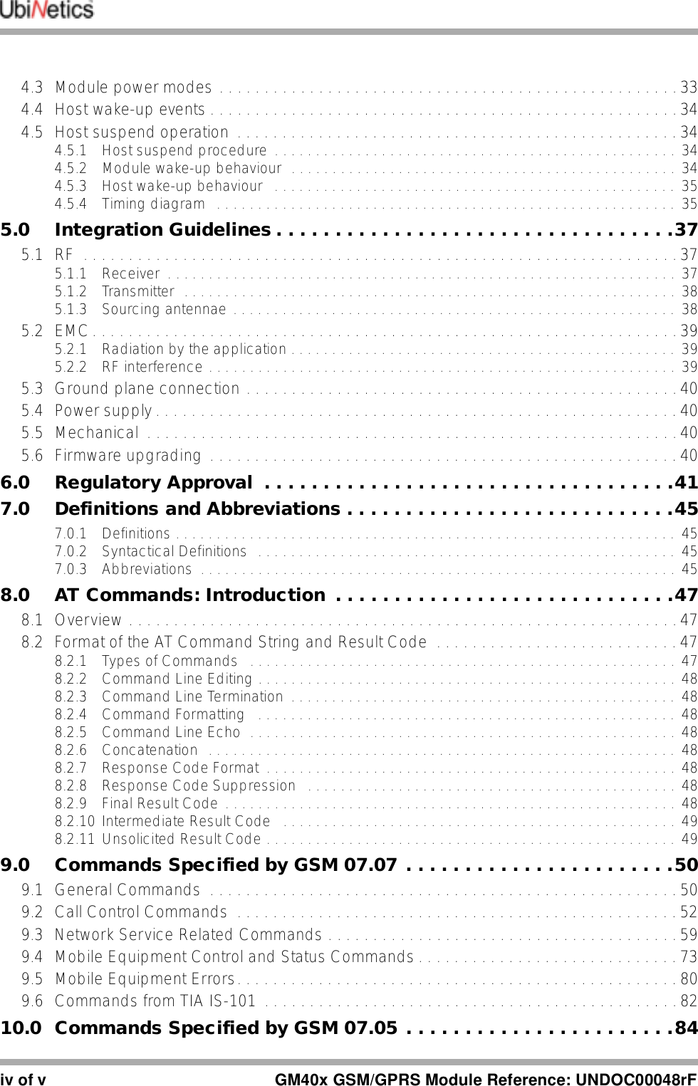
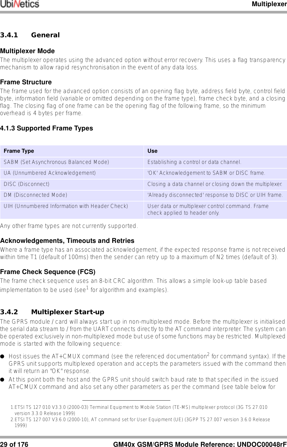
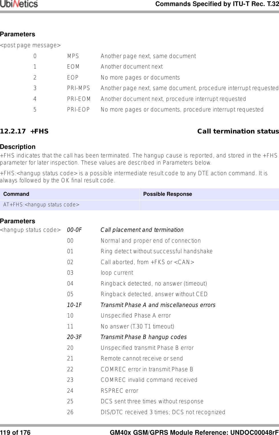
![Commands Specified by GSM 07.07GM40x GSM/GPRS Module Reference: UNDOC00048rF 52 of 1769.1.7 +WS46 Select Wireless NetworkDescriptionSelects the cellular network Wireless Data Service (WDS) to operate with the modem.Parameters<n> 12 GSM digital cellular9.1.8 +CSTA Select type of addressDescriptionSelects the type of number for further dialling commands according to GSM specifications.Parameters<type> type of address octet in integer format129 default145 default when dialling string includes the international access code character ‘+’9.2 Call Control Commands9.2.1 D Dial CommandDescriptionInitiates a mobile-originated call to the destination number <n>. Parameters<n> destination number containing the following characters 0-9,*,#,+,A,B,C,D<mgsm>, pause during dialling, ignoredCommand Possible ResponseAT+WS46=? (list of supported <n>s)AT+WS46? <n>AT+WS46=[<n>]Command Possible Response+CSTA=? +CSTA: (list of supported <type>s)+CSTA? +CSTA: <type>+CSTA=[<type>]Command Possible ResponseATD<n>[<mgsm>][;] see the table below](https://usermanual.wiki/Ubinetics/GM401.User-manual/User-Guide-233185-Page-57.png)
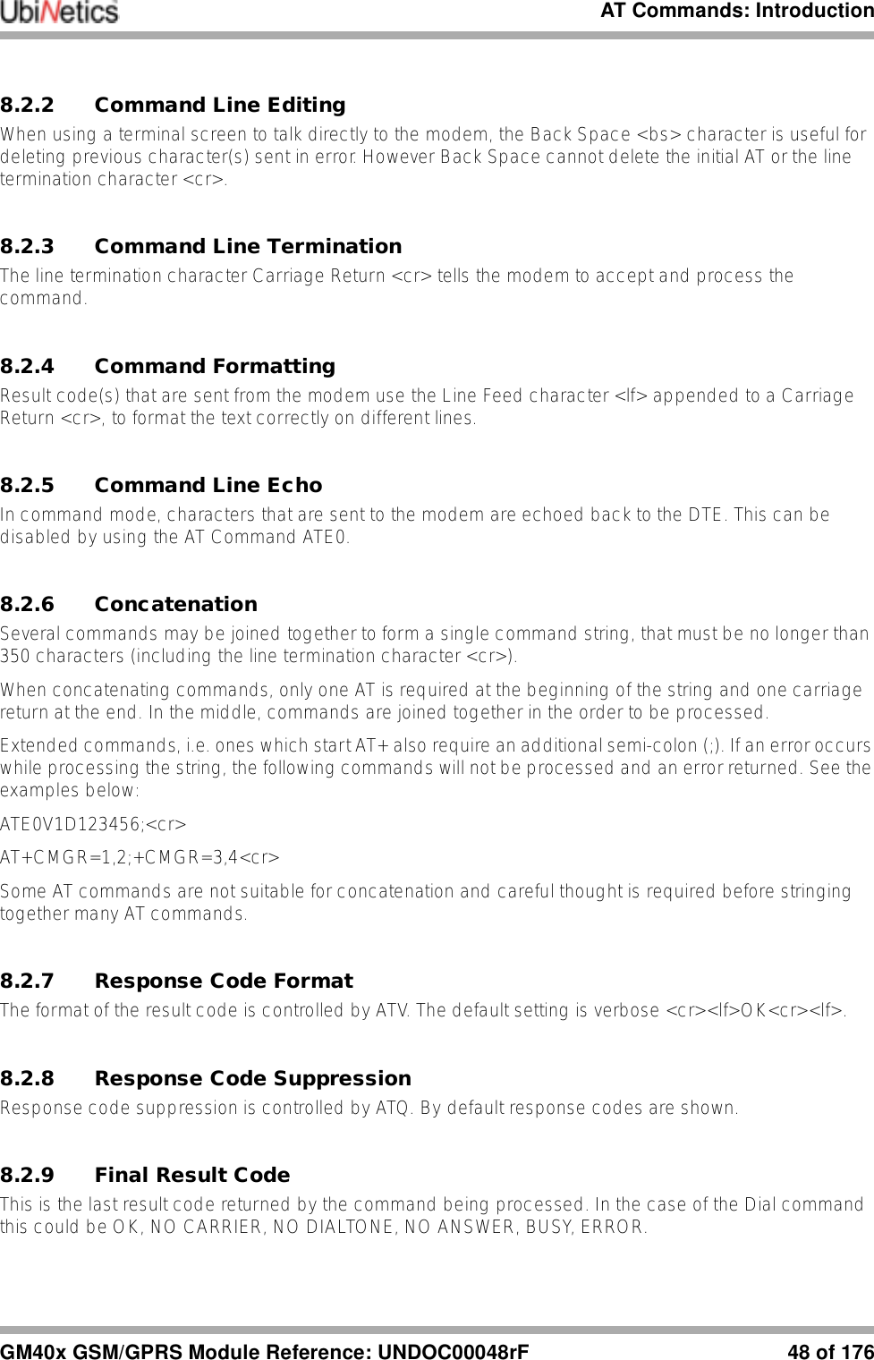
![Commands Specified by GSM 07.0753 of 176 GM40x GSM/GPRS Module Reference: UNDOC00048rFT tone dialling, ignoredP pulse dialling, ignored! register recall/hook flash, ignoredW wait for dial tone, ignored@ wait for quiet answer, ignoredI restrict CLI presentation, overriding AT+CLIR setting; originate a voice callNote: ATD112; is reserved for emergency calls only.9.2.2 D> Dial Selected Phone BookDescriptionThis command initiates a Mobile Originated call, from the specified phone book and location. Parameters<mem> EN Emergency NumberAD SIM phone book<n> Memory location of number to dialI Restrict CLI presentation, overriding AT+CLIR setting; Originate a voice call9.2.3 D> Dial Current Phone BookDescriptionInitiates a mobile originated call, from the currently selected phone book, location <n>. Verbose Result Code Numeric Result Code DescriptionOK 0Command executed, no errorCONNECT 1Connection set up (ATX=0)CONNECT <text> 1Connection set up (ATX=n) where n>0RING 2Ringing tone is present (AT+CRC=0)NO CARRIER 3Call failed to connect or disconnectedERROR 4Invalid command or too longBUSY 7The called party is currently in another callNO ANSWER 8Connection failed up to time outCommand Possible ResponseATD><mem><n>[I][;] see the table within Dial CommandCommand Possible ResponseATD><n>[I][;] see the table within Dial Command](https://usermanual.wiki/Ubinetics/GM401.User-manual/User-Guide-233185-Page-58.png)
![Commands Specified by GSM 07.07GM40x GSM/GPRS Module Reference: UNDOC00048rF 54 of 176Parameters<n> number of memory location to dialI restrict CLI presentation, overriding AT+CLIR setting; originate a voice call9.2.4 +CHMOD Call modeDescriptionSelects the call mode for dialling commands or for next answering command. The mode can be either single or alternating (for example, voice/data, voice/fax).Parameters<mode> 0 single mode1 alternating voice/fax2 alternating voice/data3 voice followed by data9.2.5 +CHUP Hangup CallDescriptionExecution command hangs up all active calls, giving an assured procedure to terminate an alternating mode call.ParametersNone.9.2.6 +CBST Select Bearer Service TypeDescriptionSet command selects the bearer service for Mobile Originated calls. Values may also be used during mobile terminated data call setup.Command Possible Response+CMOD=? +CMOD: (list of supported <mode>s)+CMOD? +CMOD: <mode>+CMOD=[<mode>]Command Possible ResponseAT+CHUP](https://usermanual.wiki/Ubinetics/GM401.User-manual/User-Guide-233185-Page-59.png)
![Commands Specified by GSM 07.0755 of 176 GM40x GSM/GPRS Module Reference: UNDOC00048rFParameters<speed> 7 9600 bps (V.32)12 9600 bps (V.34)14 14400 bps (V.34)71 9600 bps (V.110)75 14400 bps (V.110)<name> 0 data circuit asynchronous (UDI or 3.1 kHz modem)<ce> Sets whether error correction is performed by RLP, or by other means0 transparent1 non-transparent9.2.7 +CRLP Radio Link ProtocolDescriptionRadio link protocol (RLP) parameters used for non-transparent data calls.Parameters<iws> 0-61 IWF to MS window size<mws> 0-61 MS to IWF window size<t1> 39-48-255 acknowledgement timer t1, in 10ms units<n2> 1-100-255 retransmission attempts n2 (the default subject to change)Notes●Only version 1 is supported. ●<ver> and <t4> are not implemented. ●Not all of the combinations of parameters have not been tested.Command Possible ResponseAT+CBST=? +CBST: (list of supported <speed>s),(list of supported <name>s),(list of supported <ce>s)AT+CBST? +CBST: <speed>,<name>,<ce>AT+CBST=[<speed>[,<name>[,<ce>]]]Command Possible ResponseAT+CRLP=? +CRLP: (list of supported <iws>s),(list of supported <mws>s),(list of supported <t1>s),(list of supported <n2>s)]<cr><lf>[+CRLP: (list of supported <iws>s),(list of supported <mws>s),(list of supported <t1>s),(list of supported <n2>s)][...]]AT+CRLP? +CRLP: <iws>,<mws>,<t1>,<n2>][<cr><lf>+CRLP:<iws>,<mws>,<t1>,<n2>][...]]AT+CRLP=[<iws>[,<mws>[,<t1>[,<n2>]]]]](https://usermanual.wiki/Ubinetics/GM401.User-manual/User-Guide-233185-Page-60.png)
![Commands Specified by GSM 07.07GM40x GSM/GPRS Module Reference: UNDOC00048rF 56 of 1769.2.8 +CR Service Reporting ControlDescriptionSet command controls whether or not intermediate result code is returned from the modem to the DTE. If enabled, the intermediate result code is transmitted when the modem has established the speed, which is before the final result code connect.Parameters<mode> 0 disables reporting1 enables reporting<serv> service supported, displayed after connect messageASYNC asynchronous transparentREL ASYNC asynchronous non-transparent9.2.9 +CEER Extended Error ReportDescriptionThis command returns information text, which offers the user an extended report for the reason of the failure of the last unsuccessful call set up (originating or answering) or in-call modification. Parameters<report> no errorunassigned numberno route to destinationchannel unacceptableoperator determined barringnormal call clearinguser busyno user respondinguser alerting no answercall rejectednumber changedCommand Possible ResponseAT+CR=? +CR: (list of supported <mode>s)AT+CR? +CR: <mode>AT+CR=[<mode>]intermediate result code +CR: <serv>Command Possible ResponseAT+CEER +CEER: <report>](https://usermanual.wiki/Ubinetics/GM401.User-manual/User-Guide-233185-Page-61.png)
![Commands Specified by GSM 07.07GM40x GSM/GPRS Module Reference: UNDOC00048rF 58 of 176protocol errorinterworking errorbearer service not availableno TI availabletimer 303 expiryestablishment failureno erroroperation failedtimeoutbearer service not compatible9.2.10 +CRC Cellular Result CodesDescriptionSet command controls the use of extended format reporting during a MT call set up.Parameters<mode> 0 disables extended format (i.e. +RING)1 enables extended format (i.e. +CRING: VOICE)<type> ASYNC asynchronous transparentREL ASYNC asynchronous non-transparentVOICE normal voiceFAX Facsimile9.2.11 +CRING Result codeDescriptionResult code only generated when AT+CRC=1. See See “+CRC Cellular Result Codes” on page 58.Command Possible ResponseAT+CRC=? +CRC: (list of supported <mode>s)AT+CRC? +CRC: <mode>AT+CRC=[<mode>]unsolicited result code +CRING: <type>](https://usermanual.wiki/Ubinetics/GM401.User-manual/User-Guide-233185-Page-63.png)
![Commands Specified by GSM 07.0759 of 176 GM40x GSM/GPRS Module Reference: UNDOC00048rF9.3 Network Service Related Commands9.3.1 +CSNS Single Numbering SchemeDescriptionSelects the bearer or teleservice to be used when a single numbering scheme call is established.Parameters<mode> 0 voice1 alternating voice/fax; fax first (TS61)2 fax (TS 62)3 alternating voice/data, voice first (BS61)4data5 alternating voice/fax, fax first (TS61)6 alternating voice/data, data first (BS61)7 voice followed by data (BS81)9.3.2 +CNUM Subscriber NumberDescriptionAction command returns the MSISDNs related to the subscriber. If subscriber has different MSISDN for different services, each MSISDN is returned in a separate line.Parameters<alphax> optional alphanumeric string associated with <numberx><numberx> string type phone number of format specified by <typex><typex> type of address octet in integer format<speed> as defined in AT+CBST<service> service related to the phone number0 asynchronous modem Command Possible ResponseAT+CSNS=? +CSNS: (list of supported <mode>s)AT+CSNS? +CSNS: <mode>AT+CSNS=[<mode>]Command Possible ResponseAT+CNUM=?AT+CNUM +CNUM: [<alpha1>],<number1>,<type1> [,<speed>,<service>[,<itc>]][<cr><lf>+CNUM: [<alpha2>],<number2>,<type2> [,<speed>,<service>[,<itc>]][...]]](https://usermanual.wiki/Ubinetics/GM401.User-manual/User-Guide-233185-Page-64.png)
![Commands Specified by GSM 07.07GM40x GSM/GPRS Module Reference: UNDOC00048rF 60 of 1761 synchronous modem2 PAD access (asynchronous)3 packet access (synchronous)4 voice5 fax<itc> information transfer capability0 3.1 kHz1 UDI9.3.3 +CREG Network RegistrationDescriptionDisplays network registration status.Parameters<n> 0 disable network registration unsolicited result code1 enable network registration unsolicited result code<stat> 0 not registered new operator to registered and not searching1 registered, home network2 not registered, currently searching a new operator to register with3 registration denied4 unknown5 registered, roamingCommand Possible ResponseAT+CREG=? +CREG: (list of supported <n>s)AT+CREG? +CREG: <n>,<stat>AT+CREG=[<n>]unsolicited result code +CREG: <stat>](https://usermanual.wiki/Ubinetics/GM401.User-manual/User-Guide-233185-Page-65.png)
![Commands Specified by GSM 07.0761 of 176 GM40x GSM/GPRS Module Reference: UNDOC00048rF9.3.4 +COPS Operator SelectionDescriptionRegisters/displays network operators available.Parameters<stat> availability of operator0 unknown 1 available2 current3 forbidden<oper> shows the operator identity, within speech marks, in the format set by <format><mode> registration mode0 automatic (<oper> field is ignored)1 manual (<oper> field shall be present)2 de-register from network3 set only <format> (for read command AT+COPS?). Do not attempt registration / de-registration (<oper> field is ignored); this value is not applicable in read command response4 manual/automatic (<oper> field shall be present); if manual selection fails, automatic mode <mode>=0) is entered<format> format of <oper> reports0 long format alphanumeric <oper>1 short format alphanumeric <oper>2 numeric <oper>Command Possible ResponseAT+COPS=? +COPS: ([list of supported <stat>,long alphanumeric <oper>,short alphanumeric <oper>,numeric <oper>)s][,,(list of supported <mode>s),(list of supported <format>s)]AT+COPS? +COPS: <mode>[,<format>,<oper>]AT+COPS=[<mode>[,<format>[,<oper>]]]e.g.AT+COPS=1,2,"23410"](https://usermanual.wiki/Ubinetics/GM401.User-manual/User-Guide-233185-Page-66.png)
![Commands Specified by GSM 07.07GM40x GSM/GPRS Module Reference: UNDOC00048rF 62 of 1769.3.5 +CLCK Facility LockDescriptionThis command is used to lock, unlock or interrogate the modem or a network facility. A password is required for some actions.Parameters<fac> (within speech marks)SC SIM (lock SIM card) SIM asks password in modem power-up and when this lock command issuedAO BAOC (Bar All Outgoing Calls)OI BOIC (Bar Outgoing International Calls)OX BOIC-exHC (Bar Outgoing International Calls except to Home Country)AI BAIC (Bar All Incoming Calls)IR BIC-Roam (Bar Incoming Calls when Roaming outside the home country)AB All Barring servicesAG All outGoing barring servicesAC All inComing barring servicesFD SIM fixed dialling memory feature, if PIN2 authentication has not been done during the current session, PIN2 is required as <passwd><mode> 0 unlock1 lock2 query status<status> 0 not active (when mode=2, indicates no services are active)1 active<passwd> the same password used by AT+CPWD, within speech marks<classx> a sum of integers each representing a class of information1 voice (telephony)2 data (refers to all bearer services; with <mode>=2 this may refer only to some bearer service if TA does not support values 16, 32, 64 and 128)4 fax (facsimile services)7 all classesCommand Possible ResponseAT+CLCK=? +CLCK: (list of supported <fac>s)AT+CLCK=<fac>,<mode>[,<passwd>],<class>]]e.g.AT+CLCK="SC",0,"1111"when <mode>=2 and command successful;+CLCK: <status>[,<class1>[<cr><lf>+CLCK: <status>,<class2>[...]]](https://usermanual.wiki/Ubinetics/GM401.User-manual/User-Guide-233185-Page-67.png)
![Commands Specified by GSM 07.0763 of 176 GM40x GSM/GPRS Module Reference: UNDOC00048rF9.3.6 +CPWD Change PasswordDescriptionAction command sets a new password for the facility lock function defined by command facility lock (AT+CLCK).Parameters<fac> (within speech marks)SC lock SIM card, asks password in modem power-up and when this loccommand issued (SIM PIN1)AO bar All Outgoing Calls (BAOC)OI bar Outgoing International Calls (BOIC)OX bar Outgoing International Calls except to Home Country (BOIC-exHC)AI bar All Incoming Calls (BAIC)IR bar Incoming Calls when Roaming outside the home country (BIC-Roam)AB all Barring servicesAG all outGoing barring servicesAC all inComing barring servicesP2 SIM PIN2<pwdlength> integer type, maximum length of the password for the facility (see AT+CPWD=?)<oldpwd> string type; shall be the same as password specified for the facility from the modem AT command interface or with command Change Password AT+CPWD<newpwd> string type; shall be the new password for the facility from the modem AT command interface or with command Change Password AT+CPWD9.3.7 +CLIP Calling Line Identification PresentationDescriptionThis command allows the called subscriber to get the Calling Line Identity (CLI) of the calling party, in a mobile terminated call.Command Possible ResponseAT+CPWD=? +CPWD: list of supported (<fac>,<pwdlength>)sAT+CPWD=<fac>,<oldpwd>,<newpwd>e.g.AT+CPWD=”SC”,”1234”,”4321”Command Possible ResponseAT+CLIP=? +CLIP: (list of supported <n>s)AT+CLIP? +CLIP: <n>,<m>AT+CLIP=[<n>]unsolicited result code, displayed when CLI is enabled for the first two rings +CLIP: <number>,<type>](https://usermanual.wiki/Ubinetics/GM401.User-manual/User-Guide-233185-Page-68.png)
![Commands Specified by GSM 07.07GM40x GSM/GPRS Module Reference: UNDOC00048rF 64 of 176Parameters<n> sets/shows the result code presentation status in the modem0 disable1 enable<m> 0 CLIP not provisioned (parameter shows the subscriber CLIP service status in the network)1 CLIP provisioned2 unknown (e.g. no network, etc.)<number> String type phone number in "quotes", in the format specified by <type><type> type of number129 dial string without the international access character 145 dial string which includes the international access character "+"9.3.8 +CLIR Calling Line Identification RestrictionDescriptionThis command enables/disables CLI to the called party, when originating a call.Parameters<n> sets CLI status for following calls.0 presentation indicator is used according to the subscription of the CLIR service.1 CLIR invocation (hide)2 CLIR suppression (show)<m> Shows the subscriber CLIR service status in the network0 CLIR not provisioned1 CLIR provisioned in permanent mode2 unknown (e.g. no network, etc.)3 CLIR temporary mode presentation restricted4 CLIR temporary mode presentation allowedCommand Possible ResponseAT+CLIR=? +CLIR: (list of supported <n>s)AT+CLIR? +CLIR: <n>,<m>AT+CLIR=[<n>]](https://usermanual.wiki/Ubinetics/GM401.User-manual/User-Guide-233185-Page-69.png)
![Commands Specified by GSM 07.0765 of 176 GM40x GSM/GPRS Module Reference: UNDOC00048rF9.3.9 +COLP Connected Line Identification PresentationDescriptionCOLP enables a calling subscriber to get the connected line identity (COL) of the called party after setting up a mobile originated call.Parameters<n> Sets/shows the result code presentation status in the TA0 disable1 enable<m> Shows the subscriber COLP service status in the network0 COLP not provisioned1 COLP provisioned2 unknown (e.g. no network, etc.)<number> String type phone number in "brackets" of format specified by <type><type> Type of address octet in integer format. 145 when the dial string contains +, otherwise 129.9.3.10 +CCUG Closed User GroupDescriptionAllows control of the Closed User Group supplementary service.Parameters<n> 0 disable CUG temporary mode1 enable CUG temporary mode<index> 0...9 CUG index10 no index<info> 0 no information1 suppress OA2 suppress preferential CUGCommand Possible ResponseAT+COLP=? +COLP: (list of supported <n>s)AT+COLP? +COLP: <n>,<m>AT+COLP=[<n>]Intermediate result code +COLP:<number>,<type>[,<subaddr>,<satype> [,<alpha>]] Command Possible ResponseAT+CCUG=?AT+CCUG? +CCUG: <n>,<index>,<info>AT+CCUG=[<n>[,<index>[,<info>]]]](https://usermanual.wiki/Ubinetics/GM401.User-manual/User-Guide-233185-Page-70.png)
![Commands Specified by GSM 07.07GM40x GSM/GPRS Module Reference: UNDOC00048rF 66 of 1763 suppress OA and preferential CUG9.3.11 +CCFC Call Forwarding Number and ConditionsDescriptionThis command allows control over the call forwarding supplementary service providing, registration, erasure, activation, deactivation and status query.Parameters<reason> 0 unconditional1 mobile busy2 no reply3 not reachable4 all call forwarding5 all conditional call forwarding<mode> 0 disable1 enable2 query status3 registration4 erasure<number> String type phone number of forwarding address in format specified by <type><type> Type of number129 dial string without the international access character145 dial string which includes the international access character "+"<subaddr> String type sub-address of format specified by <satype><satype> Type of sub-address octet in integer format128 default<class> a sum of integers each representing a class of information1 voice (telephony)2 data (refers to all bearer services; with <mode>=2 this may refer only to some bearer service if TA does not support values 16, 32, 64 and 128)Command Possible ResponseAT+CCFC=? +CCFC: (list of supported <reason>s)AT+CCFC=<reason>,<mode>[,<number>[,<type>[,<class>[,<subaddr>[,<satype>[,<time>]]]]]]e.g. AT+CCFC=0,3,"01763262222"When <mode>=2 and command successful;+CCFC: <status>,<class1>[,<number>, <type>[,<subaddr>,<satype>[,<time>]]][<cr><lf>+CCFC: <status>,<class2>[,<number>, <type>[,<subaddr>,<satype>[,<time>]]][...]]](https://usermanual.wiki/Ubinetics/GM401.User-manual/User-Guide-233185-Page-71.png)
![Commands Specified by GSM 07.0767 of 176 GM40x GSM/GPRS Module Reference: UNDOC00048rF4 fax (facsimile services)7 All classes8 short message service16 data circuit sync32 data circuit async64 dedicated packet access128 dedicated PAD access<time> 1-20-30 when "no reply" is enabled or queried, this gives the time in seconds to wait before call is forwarded<status> 0 not active (when <mode>=2, means not active for all class)1 active9.3.12 +CCWA Call WaitingDescriptionThis command allows control over the call waiting supplementary service providing activation, deactivation, and status query.Parameters<n> sets/shows the result code presentation status in the modem0 disable1 enable<mode> when <mode> parameter is not given, network is not interrogated0 disable1 enable2 query status<class> a sum of integers each representing a class of information1 voice (telephony)2 data (refers to all bearer services; with <mode>=2 this may refer only to some bearer service if TA does not support values 16, 32, 64 and 128)4 fax8 short message serviceCommand Possible ResponseAT+CCWA=? +CCWA: (list of supported <n>s)AT+CCWA? +CCWA: <n>AT+CCWA=[<n>[,<mode>[,<class>]]] When <mode>=2 and command successful;+CCWA: <status>,<class1>[<cr><lf>+CCWA: <status>,<class2>[...]]unsolicited result code (when <n>=1) +CCWA: <number>,<type>,<class>[,<alpha>]](https://usermanual.wiki/Ubinetics/GM401.User-manual/User-Guide-233185-Page-72.png)
![Commands Specified by GSM 07.07GM40x GSM/GPRS Module Reference: UNDOC00048rF 68 of 17616 data circuit sync32 data circuit async64 dedicated packet access128 dedicated PAD access.<status>0 not active, (when <mode>=2, means not active for all class)1 active<number> string type phone number of calling address in format specified by <type><type> type of address octet in integer format<alpha> optional string type alphanumeric representation of <number> corresponding to the entry found in phonebook)9.3.13 +CHLD Call Related Supplementary ServicesDescriptionThis command allows call control using Call Hold and MultiParty.Parameters<n> integer type0 releases all held calls or sets User Determined User Busy (UDUB) for a waiting call1 releases all active calls (if any exist) and accepts the other (held or waiting) call1x releases a specific active call X2 places all active calls (if any exist) on hold and accepts the other (held or waiting) call2x places all active calls on hold except call X with which communication shall be supported3 adds a held call to the conversation4 connects the two calls and disconnects the subscriber from both calls (ECT)9.3.14 +CUSD Unstructured Supplementary Service DataDescriptionThis command allows control of the Unstructured Supplementary Service Data, for both network and mobile initiated operations.Command Possible ResponseAT+CHLD=? +CHLD: (list of supported <n>s)AT+CHLD=[<n>]Command Possible ResponseAT+CUSD=? +CUSD: (list of supported <n>s)](https://usermanual.wiki/Ubinetics/GM401.User-manual/User-Guide-233185-Page-73.png)
![Commands Specified by GSM 07.0769 of 176 GM40x GSM/GPRS Module Reference: UNDOC00048rFParameters<n> 0 disable the result code presentation in the TA1 enable the result code presentation in the TA<str> string type USSD-string; when <str> parameter is not given, network is not interrogated<dcs> Cell Broadcast Data Coding Scheme in integer format<m> 0 no further user action required (network initiated USSD-Notify, or no further information needed after mobile initiated operation)1 further user action required (network initiated USSD-Request, or further information needed after mobile initiated operation)2 USSD terminated by network3 other local client has responded4 operation not supported5 network time out Implementation 9.3.15 +CAOC Advice of chargeDescriptionAdvice of Charge supplementary service, enabling users to obtain information on the cost of calls.Parameters<mode> 0 Query CCM value1 Deactivate the unsolicited reporting of CCM value2 Activate the unsolicited reporting of CCM value9.3.16 +CSSN Supplementary Service NotificationsDescriptionSupplementary service: enables/disables network-initiated notifications.AT+CUSD? +CUSD: <n>AT+CUSD=[<n>[,<str>[,<dcs>]]]unsolicited result code +CUSD: <m>[,<str>,<dcs>]Command Possible ResponseAT+CAOC=? [+CAOC: (list of supported <mode>s]AT+CAOC? +CAOC: <mode>AT+CAOC[=<mode>] [+CAOC: <ccm>]Command Possible response](https://usermanual.wiki/Ubinetics/GM401.User-manual/User-Guide-233185-Page-74.png)
![Commands Specified by GSM 07.07GM40x GSM/GPRS Module Reference: UNDOC00048rF 70 of 176Parameters<n> CSSI result code notification0 disable1 enable<m> CSSU result code notification0 disable1 enable<code1> (manufacturer specific)0 unconditional call forwarding is active1 some of the conditional call forwardings are active2 call has been forwarded3 call is waiting4 CUG call (also <index> present)5 outgoing calls barred6 incoming calls barred7 CLIR suppression rejected8 call deflected<index> refer "Closed user group +CCUG"<code2> (manufacturer specific)0 forwarded call (MT call setup)1 CUG call (also <index> present) (MT call setup)2 call put on hold (during a voice call)3 call retrieved (during a voice call)4 multiparty call entered (during a voice call)5 call on hold has been released (not a SS notification) (during a voice call)6 forward check SS message received (can be received whenever)7 call is being connected (alerting) with the remote party in alerting state in explicit call transfer operation (during a voice call)8 call has been connected with the other remote party in explicit call transfer operation (also number and subaddress parameters may be present) (during a voice call or MT call setup)9 deflected call (MT call setup)<number> string type phone number of format specified by <type><type> type of address octet in integer formatAT+CSSN=[<n>[,<m>]]AT+CSSN? +CSSN: <n>,<m>AT+CSSN=? +CSSN: (list of supported <n>s),(list of supported <m>s)](https://usermanual.wiki/Ubinetics/GM401.User-manual/User-Guide-233185-Page-75.png)
![Commands Specified by GSM 07.0771 of 176 GM40x GSM/GPRS Module Reference: UNDOC00048rF<subaddr> string type sub-address of format specified by <satype><satype> type of sub-address octet in integer format 9.3.17 +CLCC List Current CallsDescriptionThis returns a list of current call of the modem, if any.Parameters<idx> call identification number; this number can be used in AT+CHLD command operations<dir> 0 mobile originated (MO) call1 mobile terminated (MT) call<stat> state of the call0 active1 held2 dialling (MO call)3 alerting (MO call)4 incoming (MT call)5 waiting (MT call)<mode> bearer/teleservice0 voice1 data9 unknown<mpty> 0 call is not one of multiparty (conference) call parties1 call is one of multiparty (conference) call parties<number> phone number in format specified by <type>, within "quotes"<type> type of number129 dial string without the international access character145 dial string which includes the international access character "+"<alpha> alphanumeric representation of <number> corresponding to the entry found in phonebookCommand Possible ResponseAT+CLCC [+CLCC: <id1>,<dir>,<stat>,<mode>, <mpty>[,<number>,<type>[,<alpha>]][<cr><lf>+CLCC: <id2>,<dir>,<stat>,<mode>, <mpty>[,<number>,<type>[,<alpha>]][...]]]](https://usermanual.wiki/Ubinetics/GM401.User-manual/User-Guide-233185-Page-76.png)
![Commands Specified by GSM 07.07GM40x GSM/GPRS Module Reference: UNDOC00048rF 72 of 1769.3.18 +CPOL Preferred Operator ListDescriptionThis command is used to edit the SIM preferred list of networks.Parameters<index>,<index> integer type; the order number of operator in the SIM preferred operator list. With the execute command, if <index> is left out, the next free location shall be used<format> If only the <format> is given, the result format changes for the read command0 long format alphanumeric <oper>1 short format alphanumeric <oper>2 numeric <oper><oper>,<oper> string type; <format> indicates the format of <oper>; also see AT+COPSNote: To delete an entry, give <index> but leave out <oper>.9.3.19 +COPN Read Operator NamesDescriptionThis command returns the list of operator names from the modem.Parameters<numericn> string type; operator in numeric format (see AT+COPS)<alphan> string type; operator in long alphanumeric format (see AT+COPS)Command Possible ResponseAT+CPOL=? +CPOL: (list of supported <index>s),(list of supported <format>s)AT+CPOL? +CPOL: <index1>,<format>,<oper1>[<cr><lf>+CPOL: <index2>,<format>,<oper2>[...]]AT+CPOL=[<index>][,<format>[,<oper>]]Command Possible ResponseAT+COPN=?AT+COPN +COPN: <numeric1>,<alpha1>[<cr><lf>+COPN: <numeric2>,<alpha2>[...]]](https://usermanual.wiki/Ubinetics/GM401.User-manual/User-Guide-233185-Page-77.png)
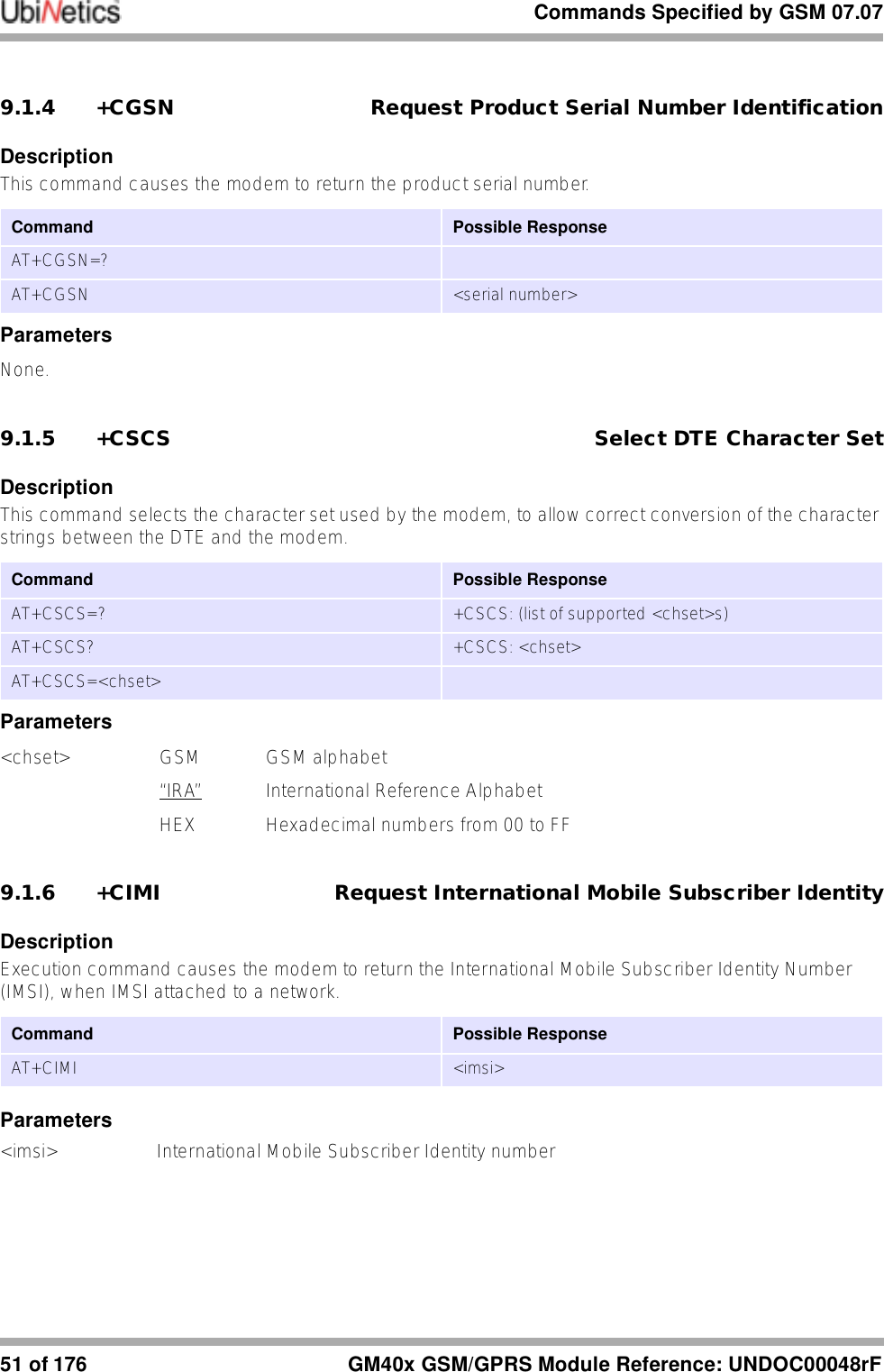
![Commands Specified by GSM 07.0773 of 176 GM40x GSM/GPRS Module Reference: UNDOC00048rF9.3.20 +CPAS Phone Activity StatusDescriptionReturns the phone activity status.Parameters<pas>0 ready allows commands1 unavailable does not allow commands2 unknown not guaranteed to respond to commands3 ringing ringer is active4 call in progress call is in progress5 asleep low functionality state9.4 Mobile Equipment Control and Status Commands9.4.1 +CFUN Set Phone FunctionalityDescriptionThis command sets the level of functionality provided by the modem.Parameters<fun> 0 sets minimum functionality. In this mode the modem de-registers from the network and powers down the SIM interface and RF circuitry1 sets full functionalityNote: An ERROR returned after entering AT+CFUN=1 usually means the SIM card cannot be read. This can be for several reasons—incorrect insertion, a damaged SIM, or a type of SIM not supported by the module.Command Possible responseAT+CPAS +CPAS: <pas>AT+CPAS=? +CPAS: (list of supported <pas>s)Command Possible ResponseAT+CFUN=? CFUN: (list of supported <fun>s)AT+CFUN? CFUN: <fun>AT+CFUN=[<fun>]](https://usermanual.wiki/Ubinetics/GM401.User-manual/User-Guide-233185-Page-78.png)
![Commands Specified by GSM 07.07GM40x GSM/GPRS Module Reference: UNDOC00048rF 74 of 1769.4.2 +CPIN Enter PINDescriptionThis command is used to query and enter a password which is necessary before the modem will operate. If the PIN is to be entered twice, the modem shall automatically repeat the PIN.Parameters<pin>,<newpin> string type values within "quotes"<code> READY no passwords requiredSIM PIN waiting for SIM PIN i.e. on power up SIM PIN 1SIM PUK waiting for SIM PUK, SIM PIN 1 unblocking code. parameter <newpin> in the new SIM PIN code.PH-SIM PIN waiting for phone-to-SIM card passwordPH-FSIM PIN waiting for phone-to-very first SIM card passwordPH-FSIM PUK waiting for phone-to-very first SIM card un-blocking passwordSIM PIN2 waiting for SIM PIN2 password. This <code> is recommended to be returned only when the last executed command resulted in PIN2 authentication failure (i.e. +CME ERROR: 17)SIM PUK2 waiting for SIM PUK2 password. This <code> is recommended to be returned only when the last executed command resulted in PUK2 authentication failure (i.e. +CME ERROR: 18)9.4.3 +CPBS Select Phone Book Memory StorageThis command selects phonebook memory storage <storage>, which is used by other phonebook commands.Parameters<storage> EN Emergency NumberCommand Possible ResponseAT+CPIN=?AT+CPIN? +CPIN: <code>AT+CPIN=<pin>[,<newpin>]e.g. AT+CPIN?+CPIN: SIM PINAT+CPIN="1234"Command Possible ResponseAT+CPBS=? +CPBS: (list of supported <storage>s)AT+CPBS? +CPBS: <storage>[,<used>,<total>]AT+CPBS=<storage>e.g.AT+CPBS="AD"](https://usermanual.wiki/Ubinetics/GM401.User-manual/User-Guide-233185-Page-79.png)
![Commands Specified by GSM 07.0775 of 176 GM40x GSM/GPRS Module Reference: UNDOC00048rFAD SIM phone bookFD SIM fixdialling-phonebookLD SIM last-dialling-phonebookBD Barred diallingLR Last-received numbersSD SIM service numbersLM Last missedAF SIM fixed<used> The number of used locations in selected memory<total> The total number of locations in selected memory9.4.4 +CPBR Read Phone Book EntriesDescriptionThis command returns the phonebook entry for location <index> of the currently selected phone book (AT+CPBS). If all queried locations are empty (but available), no information text lines may be returned.Parameters<index1>,<index2>,<index> range of location numbers of phonebook memory<number> phone number in format <type><type> type of phone number129 dial string without international access character145 dial string which includes the international access character "+"<text> text field of maximum length <tlength><nlength> value indicating the maximum length of field <number><tlength> value indicating the maximum length of field <text>Command Possible ResponseAT+CPBR=? +CPBR: (list of supported <index>s),[<nlength>],[<tlength>]AT+CPBR=<index1>[,<index2>] [+CPBR: <index1>,<number>,<type> ,<text>[[...]<cr><lf>+CPBR: <index2>,<number>,<type>,<text>]]](https://usermanual.wiki/Ubinetics/GM401.User-manual/User-Guide-233185-Page-80.png)
![Commands Specified by GSM 07.07GM40x GSM/GPRS Module Reference: UNDOC00048rF 76 of 1769.4.5 +CPBF Find Phone Book EntriesDescriptionThis command returns phonebook entries from the current phone book which alphanumeric field start with string <findtext>.Parameters<index1>,<index2> values in the range of location numbers of phonebook memory<number> phone number of format <type><type> type of phone number129 dial string without the international access character145 dial string which includes the international access character "+"<findtext>,<text> field of maximum length <tlength<nlength> value indicating the maximum length of field <number><tlength> value indicating the maximum length of field <text>)9.4.6 +CPBW Write Phone Book EntryDescriptionThis command writes an entry to location number <index> in the current phonebook. Parameters<index> range of valid location numbers for the selected phonebook memory. If this is omitted when writing an entry the first free location shall be used<number> phone number of format <type><type> type of phone number129 dial string without the international access character145 dial string which includes the international access character "+"<text> field of maximum length <tlength>Command Possible ResponseAT+CPBF=? +CPBF: [<nlength>],[<tlength>]AT+CPBF=<findtext>e.g.AT+CPBF="UbiNetics"[+CPBF: <index1>,<number>,<type> ,<text>[[...]<cr><lf>+CBPF: <index2>,<number>,<type> ,<text>]]Command Possible ResponseAT+CPBW=? +CPBW: (list of supported <index>s),[<nlength>],(list of supported <type>s),[<tlength>]AT+CPBW=[<index>][,<number>[,<type>[,<text>]]]e.g:AT+CPBW=1,”+441763262222”,145,”UbiNetics”](https://usermanual.wiki/Ubinetics/GM401.User-manual/User-Guide-233185-Page-81.png)
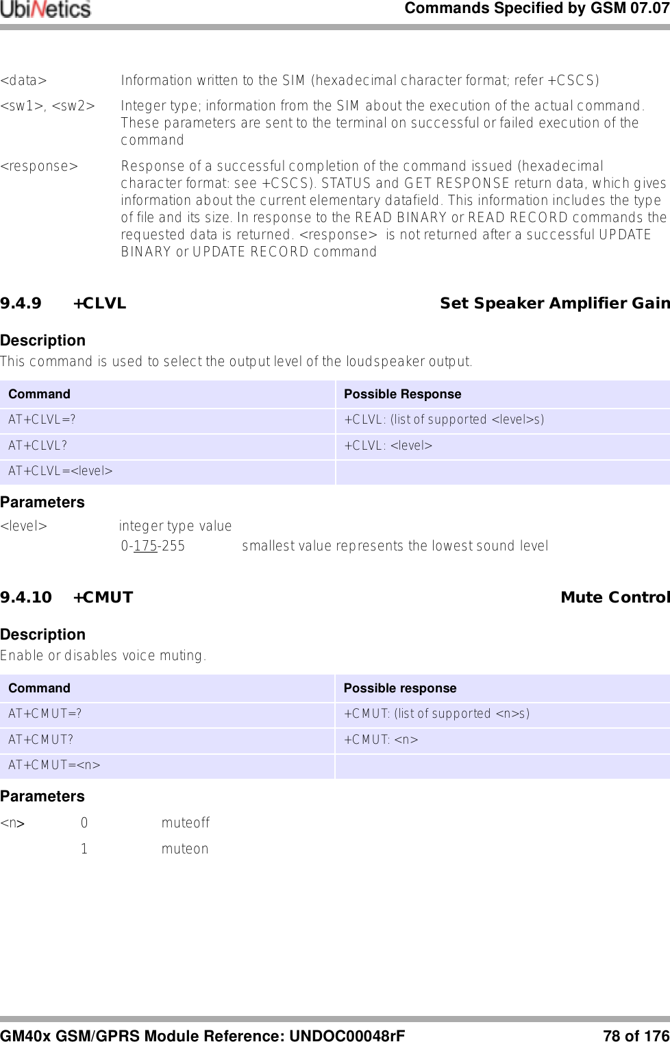
![Commands Specified by GSM 07.0777 of 176 GM40x GSM/GPRS Module Reference: UNDOC00048rF<nlength> value indicating the maximum length of field <number><tlength> value indicating the maximum length of field <text>Note: To delete an entry, only specify the <index> field.9.4.7 +CRSL Ringer Sound LevelDescriptionThis command is queries and sets, the sound level of the incoming call ringer.Parameters<level> integer type value0-175-255 smallest value represents the lowest sound level9.4.8 +CRSM Restricted SIM accessDescriptionTransmits SIM commands to mobile equipment. Can be used in place of +CSIM for easier but more limited access to the SIM database.Parameters<command> 176 READ BINARY178 READ RECORD192 GET RESPONSE214 UPDATE BINARY220 UPDATE RECORD242 STATUSAll other values are reservedNOTE: The ME internally executes all commands necessary for selecting the desired file, before performing the actual command.<fileid> Integer type: the identifier of a elementary datafile on SIM. Mandatory for every command except STATUS<P1>, <P2>, <P3>Integer type; parameters passed on by the ME to the SIM. These parameters are mandatory for every command, except GET RESPONSE and STATUS.Command Possible ResponseAT+CRSL=? +CRSL: (list of supported <level>s)AT+CRSL? +CRSL: <level>AT+CRSL=<level>Command Possible responseAT+CRSM=?AT+CRSM=<command>[,<fileid>[,<P1>,<P2>,<P3>[,<data>]]] +CRSM: <sw1>,<sw2>[,<response>]](https://usermanual.wiki/Ubinetics/GM401.User-manual/User-Guide-233185-Page-82.png)
![Commands Specified by GSM 07.0779 of 176 GM40x GSM/GPRS Module Reference: UNDOC00048rF9.4.11 +CACM Accumulated Call MeterDescriptionAllows the call meter to be read and reset.Parameters<passwd> string SIM PIN2<acm> string accumulated call meter value (see also <ccm> in +CAOC)9.4.12 +CAMM Accumulated Call Meter MaximumDescriptionAllows call meter maximum to be set and values to be read.Parameters<acmmax> string accumulated call meter maximum value (see also <ccm> in AT+CAOC)0 disables ACMmax<passwd> string SIM PIN29.4.13 +CPUC Price Per Unit and Currency TableDescriptionSets the price per unit and currency table to allow conversion between home units and other currency units.Parameters<currency> string three-character currency code (e.g. "GBP", "DEM") as specified by AT+CSCS<ppu> string price per unit; dot is used as a decimal separator (e.g. "3.34")Command Possible responseAT+CACM=?AT+CACM? +CACM: <acm>AT+CACM=[<passwd>] Command Possible responseAT+CAMM? +CAMM: <acmmax>AT+CAMM=?AT+CAMM=[<acmmax>[,<passwd>]] Command Possible responseAT+CPUC=?AT+CPUC? +CPUC: <currency>,<ppu>AT+CPUC=<currency>,<ppu>[,<passwd>]](https://usermanual.wiki/Ubinetics/GM401.User-manual/User-Guide-233185-Page-84.png)
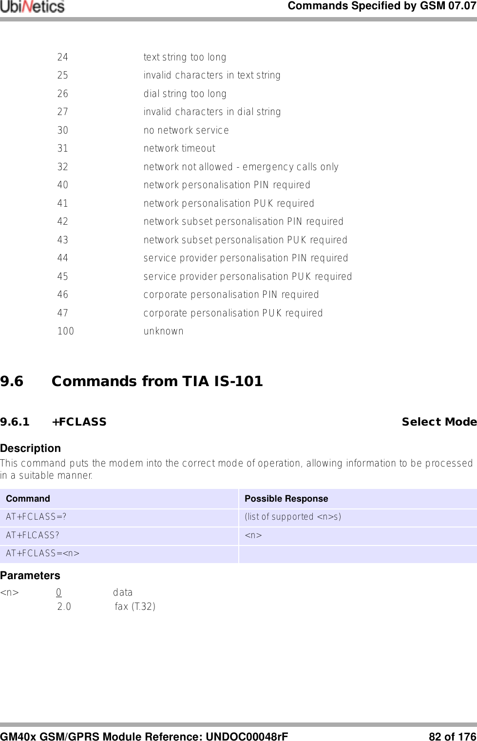
![Commands Specified by GSM 07.07GM40x GSM/GPRS Module Reference: UNDOC00048rF 80 of 176<passwd> string SIM PIN29.4.14 +CCWE Call Meter Maximum EventDescriptionDetermines whether the result code +CCWV (which warns when less than 30 seconds call time remains short of the maximum) is sent.Parameters<mode>0 Disable the call meter warning event1 Enable the call meter warning event9.4.15 +CLAC List All Available AT CommandsDescriptionReturns the AT commands available to the user.Parameters<AT Command > Defines the AT command, including the prefix AT.9.5 Mobile Equipment Errors9.5.1 +CMEE Mobile Equipment ErrorsDescriptionThis command controls the presentation of result codes, generated by errors relating the functionality of the modem.Command Possible responseAT+CCWE=? +CCWE: (list of supported<mode>s)AT+CCWE? +CCWE: <mode>AT+CCWE=<mode> Command Possible responseAT+CLAC <AT Command1> [<CR> <LF> <ATCommand2>[…]]AT+CLAC=? Command Possible ResponseAT+CMEE =? +CMEE: (list of supported <n>s)](https://usermanual.wiki/Ubinetics/GM401.User-manual/User-Guide-233185-Page-85.png)
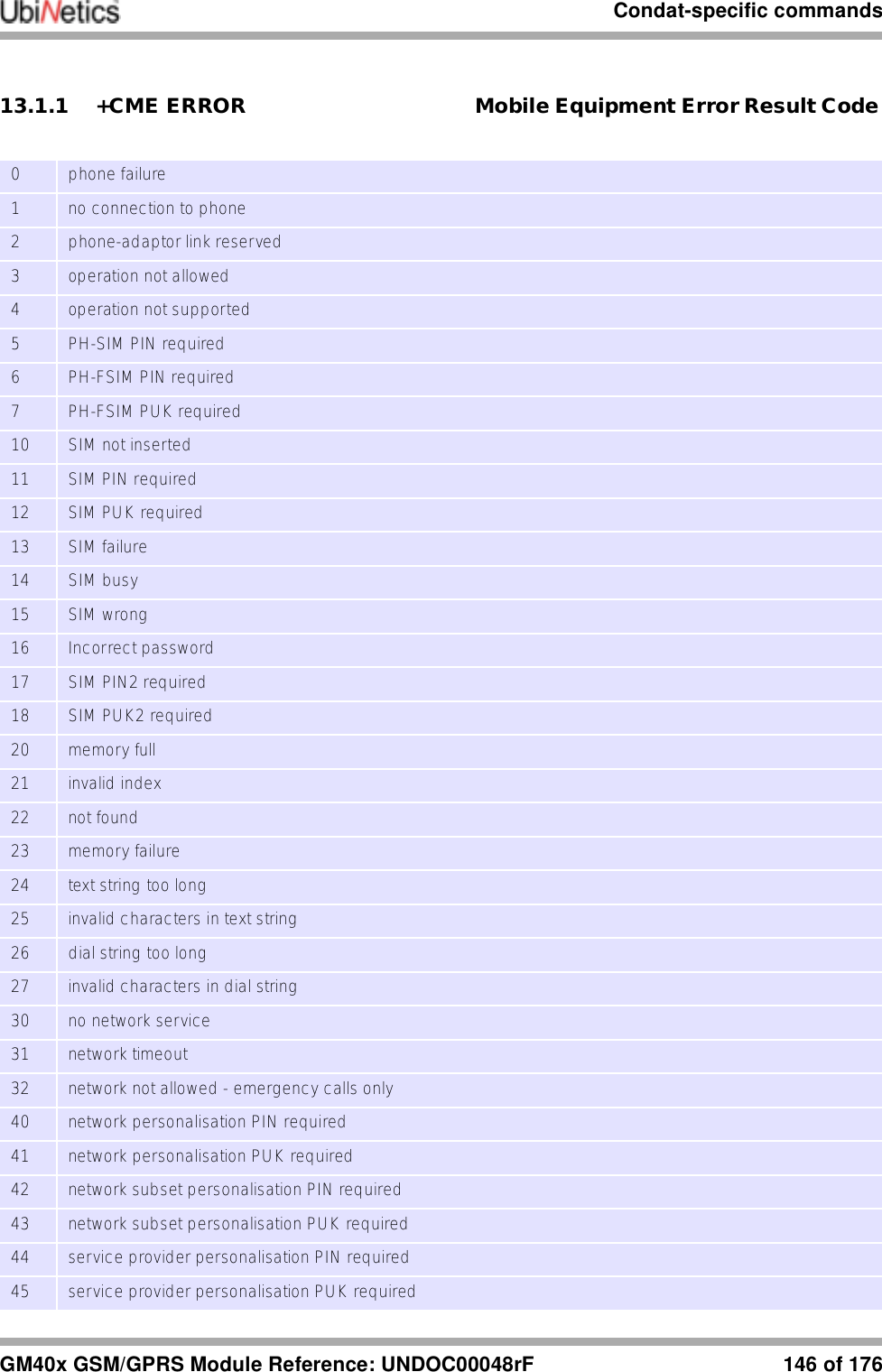
![Commands Specified by GSM 07.0781 of 176 GM40x GSM/GPRS Module Reference: UNDOC00048rFParameters<n> 0 disable result code and use ERROR instead1 enable result code and use numeric <err> values2 enable result code and use verbose <err> values<err> for a complete list of error codes, see CME result codes.9.5.2 +CME ERROR Mobile Equipment Error Result CodeDescriptionSimilar in operation to the normal ERROR result code. None of the following commands in the same command line is executed.Parameters<err> Numeric format Verbose format0 Phone failure1 No connection to phone2 Phone-adaptor link reserved3 Operation not allowed4 Operation not supported5 PH-SIM PIN required6 PH-FSIM PIN required7 PH-SIM PUK required10 SIM not inserted11 SIM PIN required12 SIM PUK required13 SIM failure14 SIM busy15 SIM wrong16 incorrect password17 SIM PIN2 required18 SIM PUK2 required20 memory full21 invalid index22 not found23 memory failureAT+CMEE? +CMEE: <n>AT+CMEE=[<n>]result code +CME ERROR: <err>](https://usermanual.wiki/Ubinetics/GM401.User-manual/User-Guide-233185-Page-86.png)
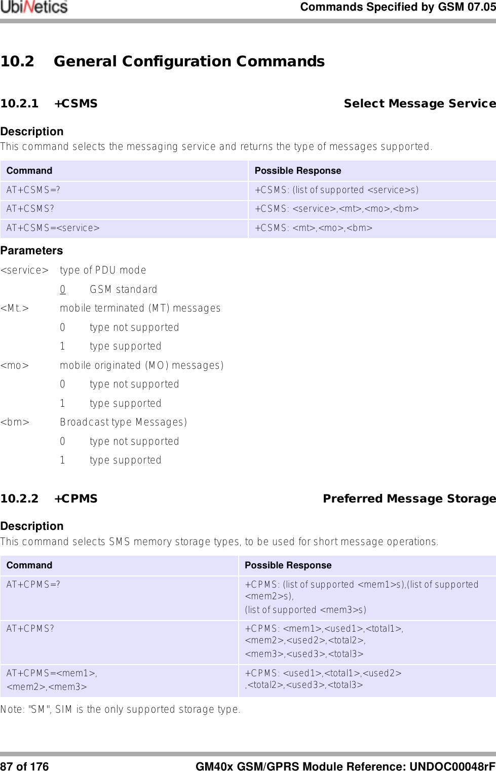
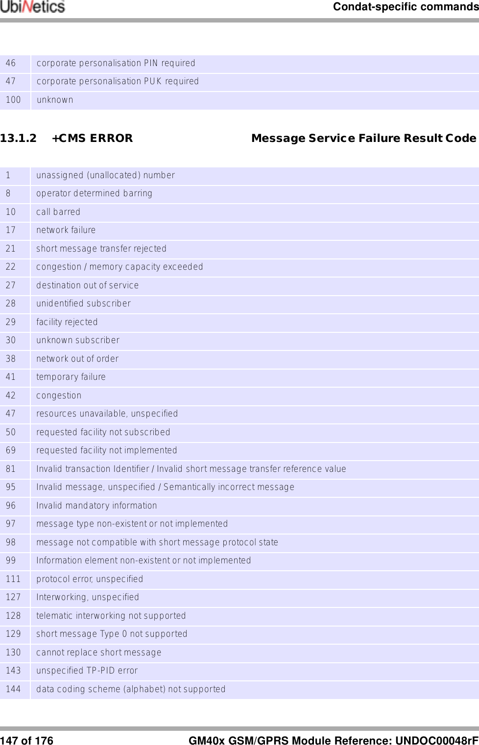
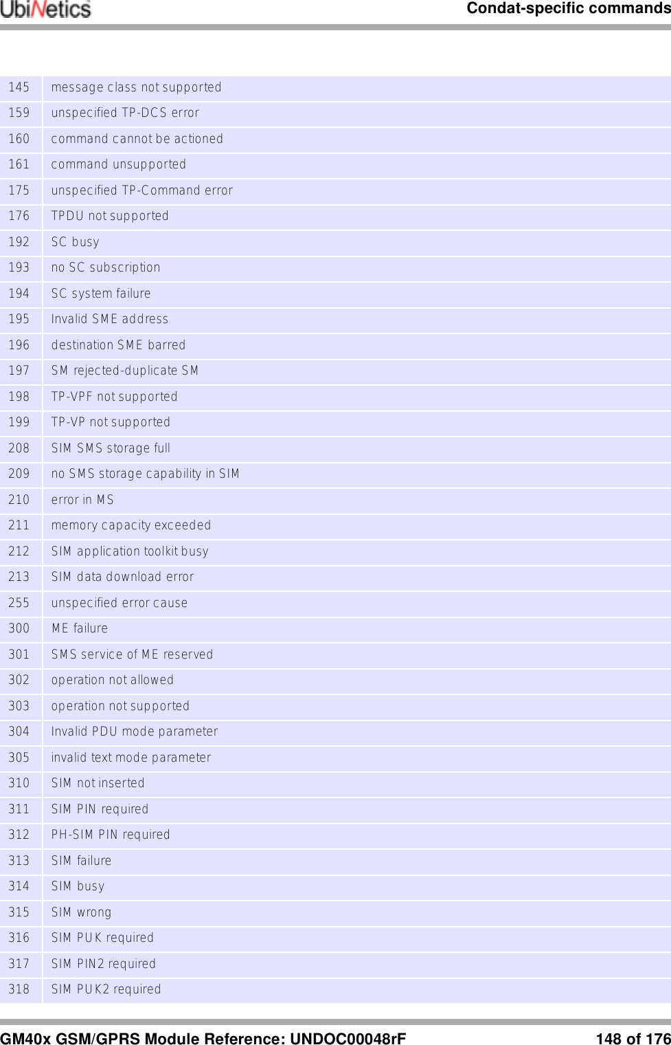
![Commands Specified by GSM 07.05GM40x GSM/GPRS Module Reference: UNDOC00048rF 88 of 17610.2.3 +CMGF SMS FormatDescriptionThis command controls the presentation format of short messages from the modem. Parameters<mode> 0 PDU mode1text mode10.2.4 +CMS ERROR Message Service Failure Result CodeDescriptionResult code indicating an error related to mobile equipment or the network. Similar in operation to the normal ERROR result code. None of the following commands in the same command line is executed.ParametersSee “+CMS ERROR Message Service Failure Result Code” on page 147.10.3 Message Configuration Commands10.3.1 +CSCA Service Centre AddressDescriptionThis command updates the short message service centre address, through which mobile-originated short messages are transmitted.Note: Subscription to this service may be required. This number can be obtained from your network provider. Below is a list of the UK service centres:BT Cellnet +447802000332 Vodafone +447785016005Orange +447973100973Command Possible ResponseAT+CMGF=? +CMGF: (list of supported <mode>s)AT+CMGF? +CMGF: <mode>AT+CMGF=<mode>Command Possible ResponseAT+CSCA=?AT+CSCA? +CSCA: <sca>,<tosca>AT+CSCA=<sca>[,<tosca>]e.g.AT+CSCA=”+44973100973”,145](https://usermanual.wiki/Ubinetics/GM401.User-manual/User-Guide-233185-Page-93.png)
![Commands Specified by GSM 07.0589 of 176 GM40x GSM/GPRS Module Reference: UNDOC00048rFOne 2 One +447958879879Virgin +44795887989010.3.2 +CSMP Set Text Mode ParametersDescriptionThis command used to select values for additional parameters needed when short message is sent to the network or placed in storage when text format message mode is selected.10.3.3 +CSDH Show Text Mode ParametersDescriptionThis command controls whether detailed header information is shown in text mode result codes.Parameters<show> 0 do not show header values1show the values in result codes10.3.4 +CSCB Select Cell Broadcast Message TypesDescriptionThis command selects which types of Cell Broadcast Messages are to be received by the modem.Parameters<mode> 0 message types specified in <mids> and <dcss> are accepted<mids> all different possible combinations of CBM message identifiers<dcss> all different possible combinations of CBM data coding schemesCommand Possible ResponseAT+CSMP=? +CPMS: (list of supported <fo>s),(list of supported <vp>s),(list of supported <pid>s),(list of supported <dcs>s)AT+CSMP? +CSMP: <fo>,<vp>,<pid>,<dcs>AT+CSMP=[<fo>[,<vp>[,<pid>[,<dcs>]]]]Command Possible ResponseAT+CSDH=? +CSDH: (list of supported <show>s)AT+CSDH? +CSDH: <show>AT+CSDH=[<show>]Command Possible ResponseAT+CSCB? +CSCB: <mode>,<mids>,<dcss>AT+CSCB=[<mode>[,<mids>[,<dcss>]]]](https://usermanual.wiki/Ubinetics/GM401.User-manual/User-Guide-233185-Page-94.png)
![Commands Specified by GSM 07.05GM40x GSM/GPRS Module Reference: UNDOC00048rF 90 of 17610.3.5 +CSAS Save SettingsDescriptionSaves active message service settings to NV RAM. Several profiles of settings may be stored at a TA, referenced by a setting number. Settings are specified by the commands +CSCA, +CSMP and +CSCB.Parameters<profile>0...255 manufacturer specific profile number10.3.6 +CRES Restore SettingsDescriptionRestores message service settings from a profile held in NV memory to active memory.Parameters<profile>0...255 manufacturer specific profile number10.4 Message Receiving and Reading Commands10.4.1 +CNMI New Message Indications to DTEDescriptionThis command selects the procedure, how receiving of new messages from the network is indicated to the DTE when DTE is active. Further information can be found in GSM 03.38.Parameters<mode> 0 buffer unsolicited result codes in the modem. When the buffer is full, indications may be discarded.Command Possible responseAT+CSAS=? +CSAS: (list of supported <profile>s)AT+CSAS[=<profile>] Command Possible responseAT+CRES=? +CRES: (list of supported <profile>s)AT+CRES[=<profile>] Command Possible ResponseAT+CNMI=? +CNMI: (list of supported <mode>s),(list of supported <mt>s),(list of supported <bm>s),(list of supported <ds>s),(list of supported <bfr>s)AT+CNMI? +CNMI: <mode>,<mt>,<bm>,<ds>,<bfr>AT+CNMI=[<mode>[,<mt>[,<bm>[,<ds>[,<bfr>]]]]]](https://usermanual.wiki/Ubinetics/GM401.User-manual/User-Guide-233185-Page-95.png)
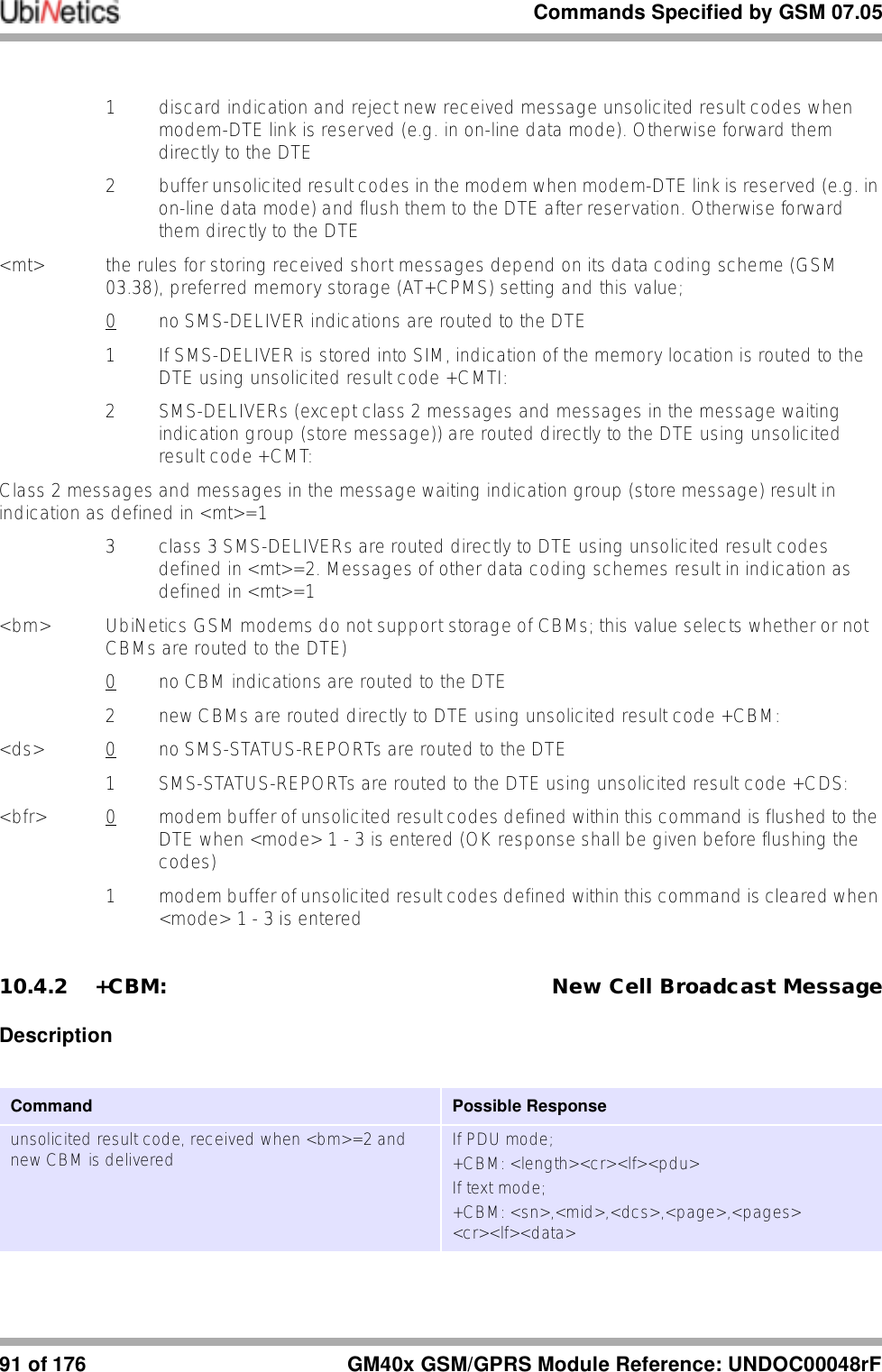
![Commands Specified by GSM 07.05GM40x GSM/GPRS Module Reference: UNDOC00048rF 92 of 17610.4.3 +CMT: New Mobile Terminated Short MessageDescription10.4.4 +CDS: New SMS status report messageDescription10.4.5 +CMTI: New Mobile Terminated Short Message IndicatorDescription10.4.6 +CMGL List MessagesDescriptionThis command returns messages with status value <stat> from message storage <mem1> to the DTE. If status of the message is 'received unread', status in the storage changes to 'received read'.Command Possible Responseunsolicited result code, received when <mt>=2 and new short message is delivered If PDU mode;+CMT: [<alpha>],<length><cr><lf><pdu>If text mode;+CMT: <oa>,[<alpha>],<scts>[,<tooa>, <fo>,<pid>,<dcs>,<sca>,<tosca>,<length>] <cr><lf><data>Command Possible ResponseSMS-STATUS-REPORTs are routed to the DTE using unsolicited result code +CDS: <length><cr><lf><pdu> (PDU mode enabled)+CDS: <fo>,<mr>,[<ra>],[<tora>],<scts>,<dt>,<st> (text mode enabled)Command Possible Responseunsolicited result code, is sent by the modem when a new short message is received. +CMTI: <mem>,<index>](https://usermanual.wiki/Ubinetics/GM401.User-manual/User-Guide-233185-Page-97.png)
![Commands Specified by GSM 07.0593 of 176 GM40x GSM/GPRS Module Reference: UNDOC00048rF10.4.7 +CMGR Read MessageDescriptionThis command returns short message from location <index>, of message storage <mem1> to the DTE. If status of the message is 'received unread', status in the storage changes to 'received read'.10.4.8 +CNMA New Message AcknowledgementDescriptionConfirms receipt of new message routed directly to the DTE. Used when +CSMS parameter <service> equals 1.Command Possible ResponseAT+CMGL=? +CMGL: (list of supported <stat>s)AT+CMGL[=<stat>] If text mode, command successful and SMS-SUBMITs and/or SMS-DELIVERs:+CMGL: <index>,<stat>,<oa/da>,[<alpha>],[<scts>][,<tooa/ toda>,<length>]<cr><lf><data>[<cr><lf>+CMGL: <index>,<stat>,<da/oa>,[<alpha>],[<scts>][,<tooa/toda>, <length>]<cr><lf><data>[...]] If PDU mode, command successful:+CMGL: <index>,<stat>,[<alpha>],<length><cr><lf><pdu>[<cr><lf>+CMGL:<index>,<stat>,[<alpha>],<length><cr><lf><pdu>[...]]Command Possible ResponseAT+CMGR=?AT+CMGR=<index> If text mode, command successful and SMS-DELIVERs;+CMGR: <stat>,<oa>,[<alpha>],<scts>[,<tooa>,<fo>,<pid>, <dcs>,<sca>,<tosca>,<length>]<cr><lf><data>if text mode, command successful and SMS-SUBMIT;+CMGR: <stat>,<da>,[<alpha>][,<toda>,<fo>,<pid>, <dcs>,[<vp>],<sca>,<tosca>,<length>]<cr><lf><data>If PDU mode, command successful;+CMGR: <stat>,[<alpha>],<length><cr><lf><pdu>](https://usermanual.wiki/Ubinetics/GM401.User-manual/User-Guide-233185-Page-98.png)
![Commands Specified by GSM 07.05GM40x GSM/GPRS Module Reference: UNDOC00048rF 94 of 17610.5 Message Sending and Writing Commands10.5.1 +CMGS Send MessageDescriptionThis command sends a short message from the modem to the network (SMS-SUBMIT).Note:●Control+z = terminate and send, escape = terminate and quit (without sending).●After sending the command AT+CMGS="123456"<cr> wait for the character > before sending the text or characters will be lost.●The text string is terminated by ctrl+z do not use a carriage return like other commands.Command Possible responseif text mode (+CMGF=1):AT+CNMAAT+CNMA=?Command Possible ResponseIf text mode;AT+CMGS=<da>[,<toda>]<cr>text is entered <ctrl+z/esc>If PDU mode;AT+CMGS=<length><cr>PDU mode is given <ctrl+z/esc>e.g. (text mode)AT+CMGS=”01763262222”<cr>>Write your test here <ctrl+z>If text mode and sending successful;+CMGS: <mr>If PDU mode and sending successful;+CMGS: <mr>](https://usermanual.wiki/Ubinetics/GM401.User-manual/User-Guide-233185-Page-99.png)
![Commands Specified by GSM 07.0595 of 176 GM40x GSM/GPRS Module Reference: UNDOC00048rF10.5.2 +CMSS Send Message from StorageDescriptionThis command sends a message from SIM storage location value <index> (SMS-SUBMIT).10.5.3 +CMGW Write Message to MemoryDescriptionThis command writes a message to SIM storage (either SMS-DELIVER or SMS-SUBMIT) to memory storage <mem2>. By default message status will be set to 'stored unsent', but parameter <stat> allows also other status values to be given.Note:●Control+z = terminate and write, escape = terminate and quit (without writing).●After sending the command AT+CMGW="123456"<cr> wait for the character > before sending the text or characters will be lost.●The text string is terminated by ctrl+z do not use carriage return like other commands.10.5.4 +CMGC Send CommandDescriptionSends a command message from the DTE to the network.Command Possible ResponseAT+CMSS=?AT+CMSS=<index>[,<da>[,<toda>]]e.g. (text mode)AT+CMSS=1,”01763262222”<cr>If text mode and sending successful;+CMSS: <mr>If PDU mode and sending successful;+CMSS: <mr>Command Possible ResponseIf text mode;AT+CMGW[=<oa/da>[,<tooa/toda>[,<stat>]]]<cr>text is entered<ctrl+z>If PDU mode;AT+CMGW=<length>[,<stat>]<cr>PDU is given<ctrl+z>e.g. (text mode)AT+CMGW=”01763262222”<cr>Write your test message here <ctrl+z>+CMGW: <index>](https://usermanual.wiki/Ubinetics/GM401.User-manual/User-Guide-233185-Page-100.png)
![Commands Specified by GSM 07.05GM40x GSM/GPRS Module Reference: UNDOC00048rF 96 of 17610.5.5 +CMGD Delete MessageDescriptionThis command deletes a message from the location <index> from SIM storage.Command Possible responseif text mode (AT+CMGF=1):AT+CMGC=<fo>,<ct>[,<pid>[,<mn>[,<da>[,<toda>]]]]<CR>text is entered<ctrl-z/Esc>if text mode (+CMGF=1) and sending successful:+CMGC: <mr>[,<scts>]if sending fails:AT+CMGC=?Command Possible ResponseAT+CMGD=?AT+CMGD=<index>](https://usermanual.wiki/Ubinetics/GM401.User-manual/User-Guide-233185-Page-101.png)
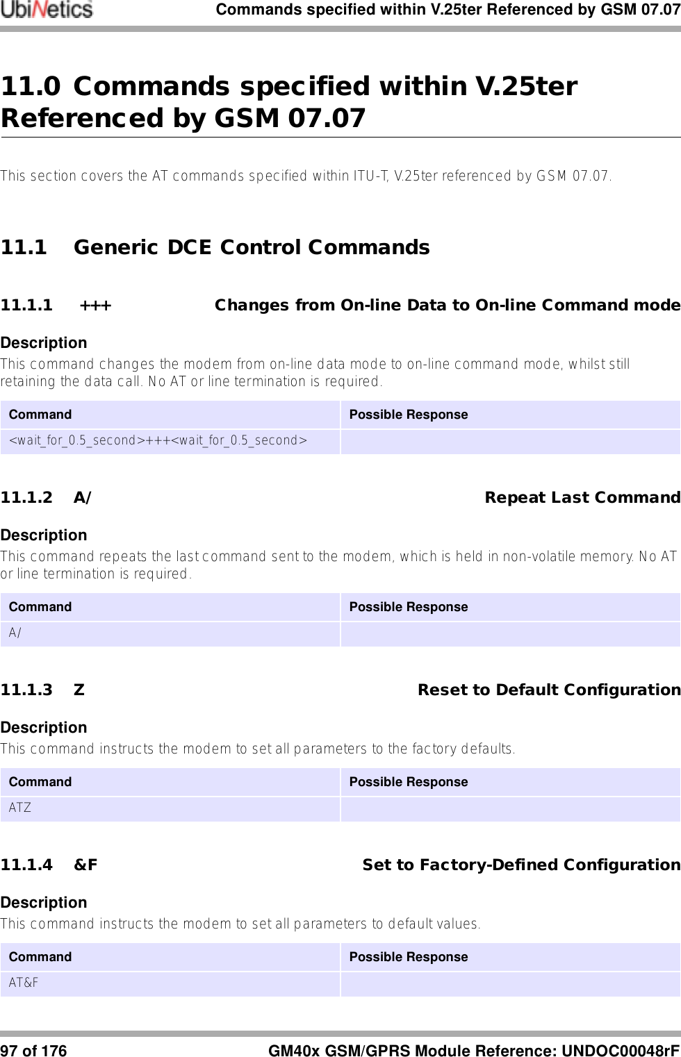
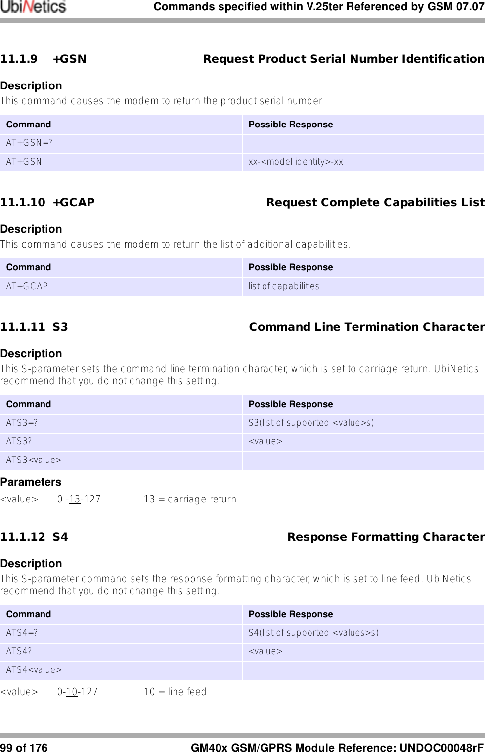
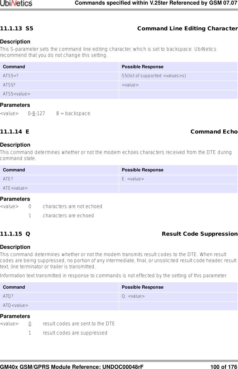
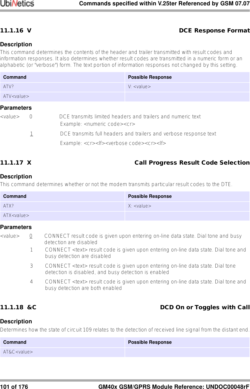
![Commands specified within V.25ter Referenced by GSM 07.07GM40x GSM/GPRS Module Reference: UNDOC00048rF 98 of 17611.1.5 I Request Identification InformationDescriptionThis command causes the modem to transmit the manufacturer specific information about the modem.11.1.6 +GMI Request Manufacturer IdentificationDescriptionExecution command causes the modem to return the manufacturer specific identity.11.1.7 +GMM Request Model IdentificationDescriptionExecution command causes the modem to return the manufacturer specific model identity.11.1.8 +GMR Request Model RevisionDescriptionExecution command causes the modem to return the manufacturer specific model revision identity.Command Possible Response GM400For the GM400ATI[0]ATI1ATI2ATI3ATI4ATI5ATI614400Ubinetics Ltd.Ubinetics Ltd.<software version>Ubinetics Ltd.Dual Band PC CardDesigned in UKCommand Possible ResponseAT+GMI=?AT+GMI Ubinetics Ltd.Command Possible ResponseAT+GMM=?AT+GMM <model identity>Command Possible ResponseAT+GMR=?AT+GMR <revision>](https://usermanual.wiki/Ubinetics/GM401.User-manual/User-Guide-233185-Page-103.png)
![Commands specified within V.25ter Referenced by GSM 07.07103 of 176 GM40x GSM/GPRS Module Reference: UNDOC00048rF11.1.21 +ICF DTE-DCE character framingDescriptionUsed to determine the local serial port start-stop (asynchronous) character framing that the DCE shall use while accepting DTE commands and while transmitting information text and result code, if this is not automatically determined.+IPR=0 forces +ICF=0 (see “+IPR Fixed DTE-DCE Rate” on page 102). Note that the definition of fixed character format for OnLine Data State is for further study.<format> determines the number of bits in the data bits, the presence of a parity bit, and the number of stop bits in the start-stop frame. NOTE: The semantics of this command are derived from Recommendation V.58.<parity> determines how the parity bit is generated and checked, if present.Parameters<format> 0 auto detect (not currently supported)1 8 Data 2 Stop2 8 Data 1 Parity 1 Stop3 8 Data 1 Stop4 7 Data 2 Stop5 7 Data 1 Parity 1 Stop6 7 Data 1 Stop<parity> 0 Odd1 Even2 Mark3 Space11.1.22 +IFC DTE-DCE Local Flow ControlDescriptionThis command is used to control the operation of local flow control between the DTE and modem.Command Possible Response+ICF=? +ICF:(list of supported <format> values),(list of supported <parity> values)+ICF? +ICF:<format>,<parity>+ICF=[<format>[,<parity>]]Command Possible ResponseAT+IFC=? +IFC: (list of supported <DCE/DTE values),(list of supported <DTE/DCE values)AT+IFC? +IFC: <DCE/DTE>,<DTE/DCE>AT+IFC=[<DCE/DTE>[,<DTE/DCE>]]](https://usermanual.wiki/Ubinetics/GM401.User-manual/User-Guide-233185-Page-108.png)
![Commands specified within V.25ter Referenced by GSM 07.07GM40x GSM/GPRS Module Reference: UNDOC00048rF 104 of 176Parameters<DCE/DTE> DTE to control the flow of received data from the modem0 none1 XON/XOFF software flow control (filtered characters)2 RTS hardware flow control<DTE/DCE> modem to control the flow of transmitted data from the DTE0 none1 XON/XOFF software flow control2 CTS hardware flow controlNote: The flow control values must be set in pairs, i.e. RTS/CTS, XON/XOFF, NONE/NONE. 11.1.23 +ILRR DTE-DCE Local Rate ReportingDescriptionControls whether or not the current local port rate is transmitted from the DCE to the DTE.Parameters<value> 0 disables reporting (i.e. +ILRR is not reported)1 enables reporting<rate> TXD rate (decimal value, range 77-115200)11.2 Call Control Commands and Responses11.2.1 W Wait for Dial ToneDescriptionCauses the DCE to wait for a dial tone. If a valid dial tone is detected, the DCE continues processing the remainder of the dial string.Notes: ●implemented for legacy support only: no function in GSM●this command and the next two implemented by the Dial command.Command Possible ResponseAT+ILRR=? +ILRR:(list of supported values)AT+ILRR? +ILRR:<rate>AT+ILRR=<value> AT+ILRR: <rate>[,<rx_rate>]Command Possible ResponseATDW](https://usermanual.wiki/Ubinetics/GM401.User-manual/User-Guide-233185-Page-109.png)
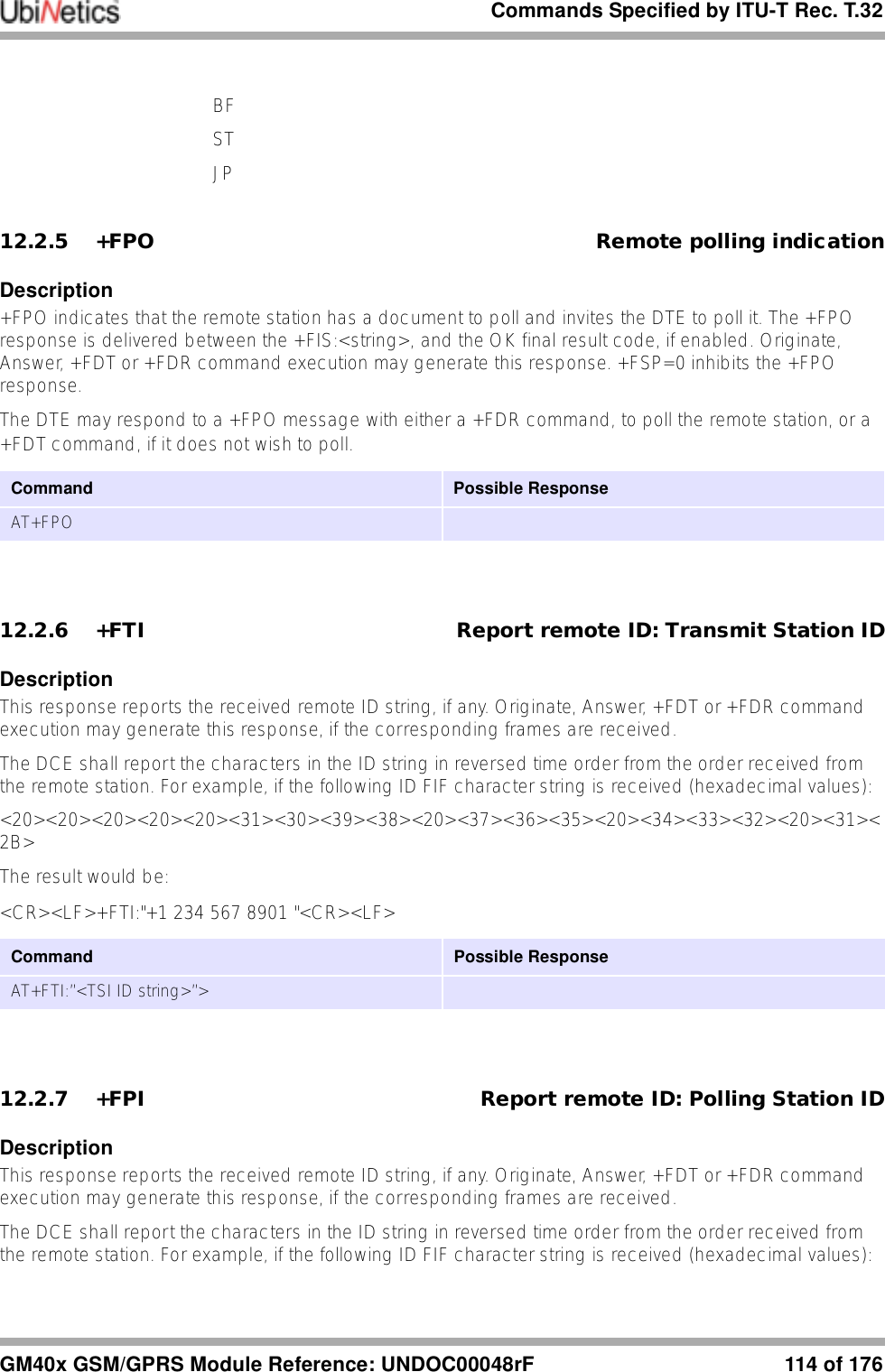
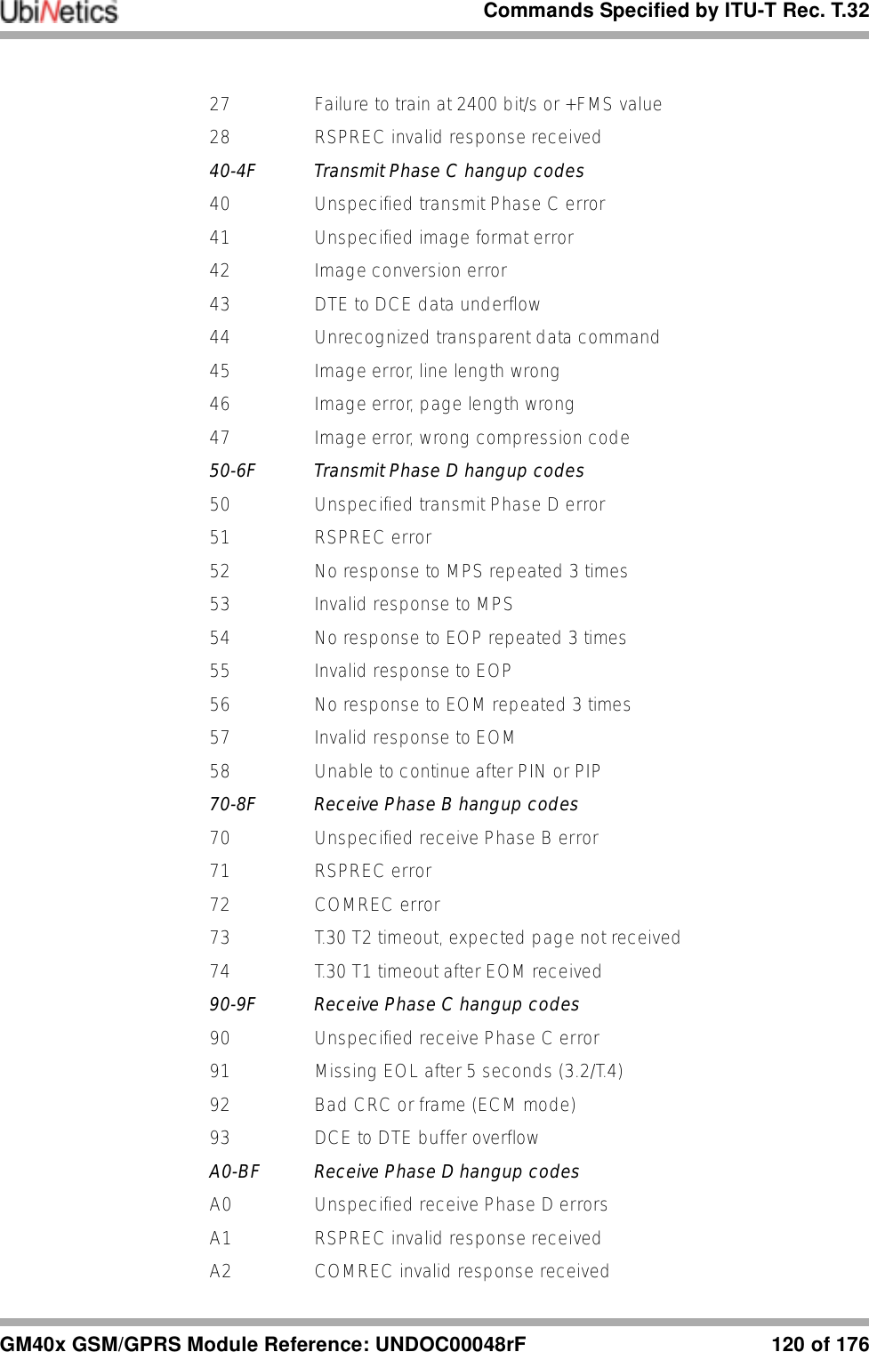
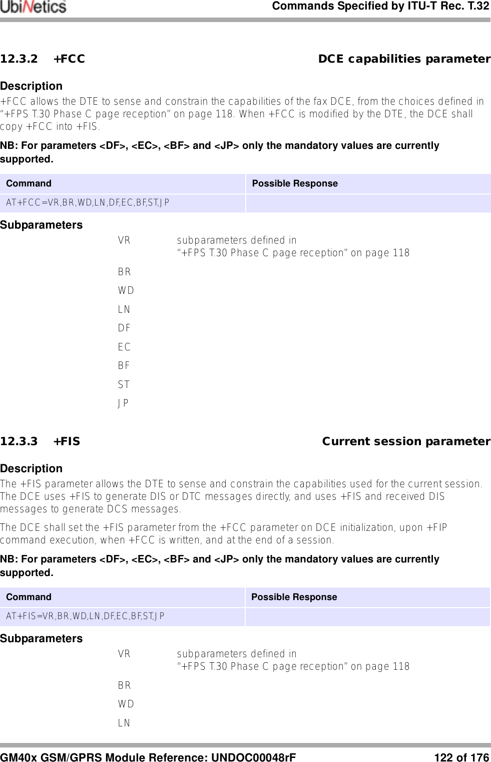
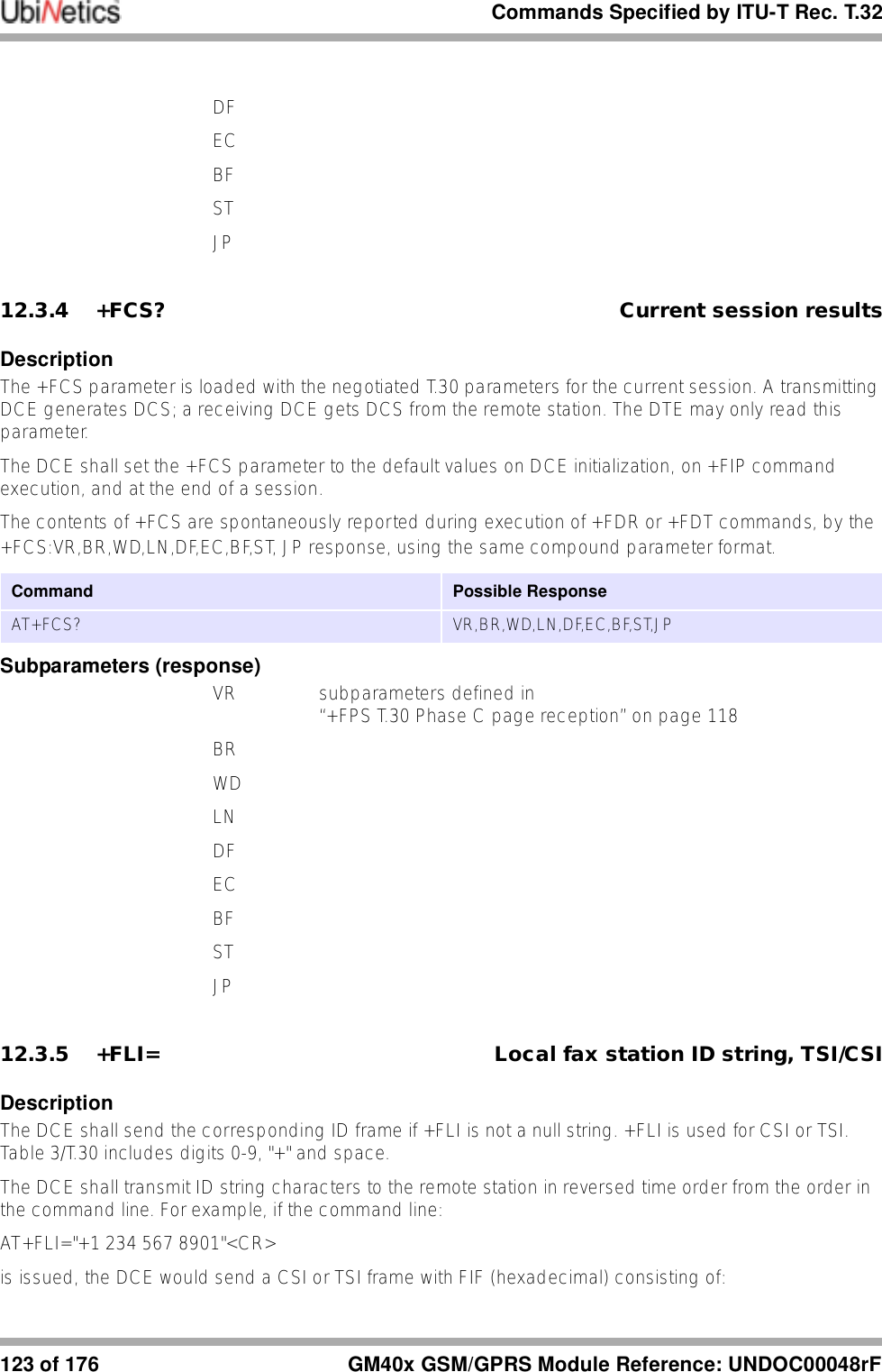
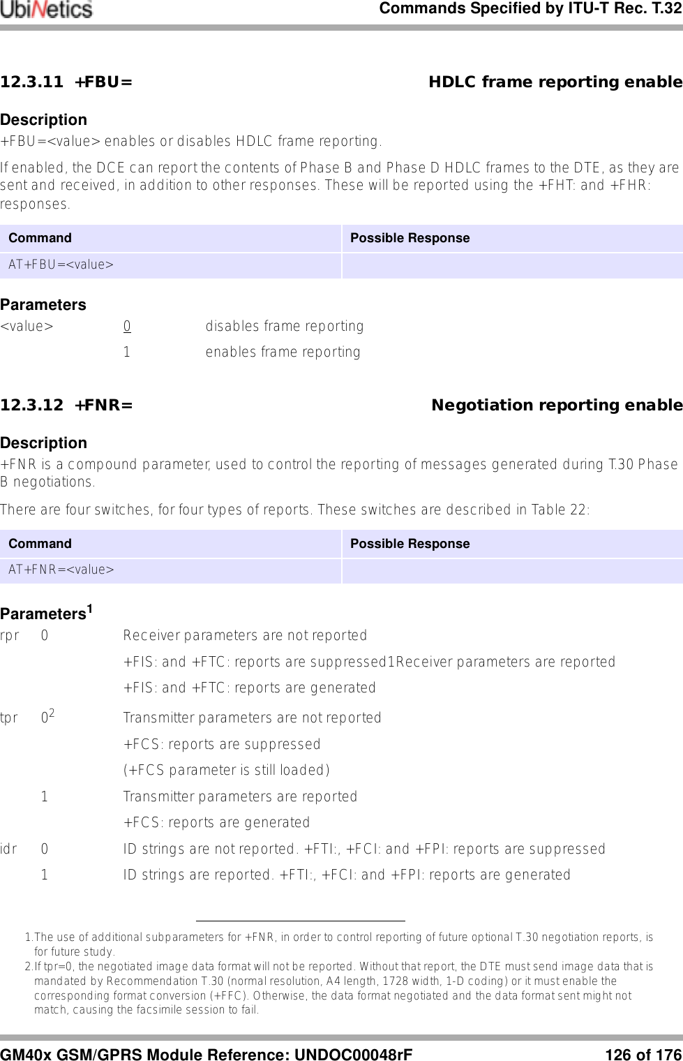
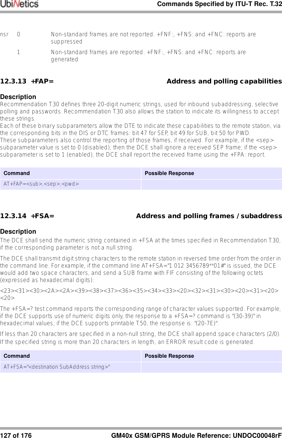
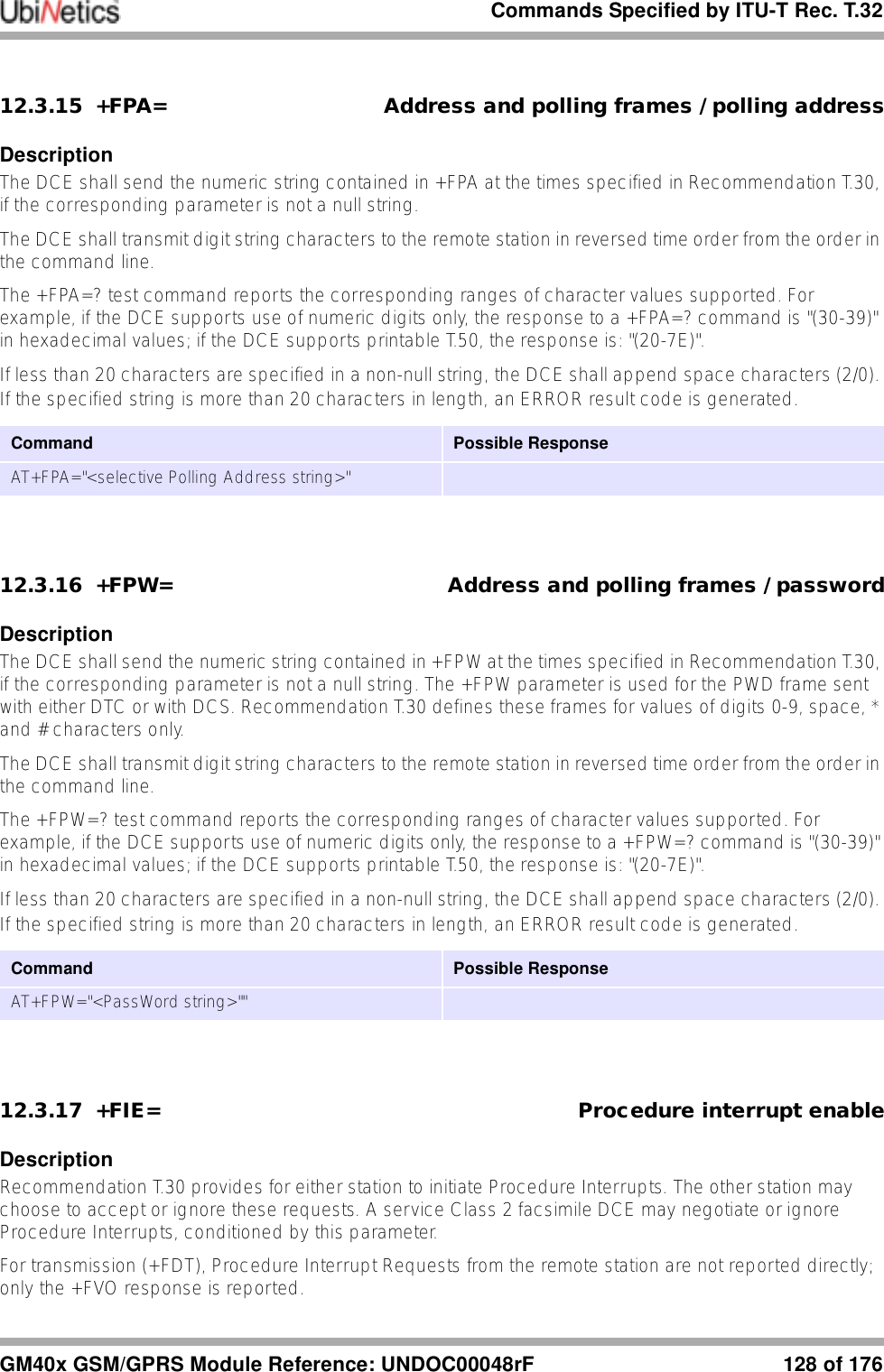
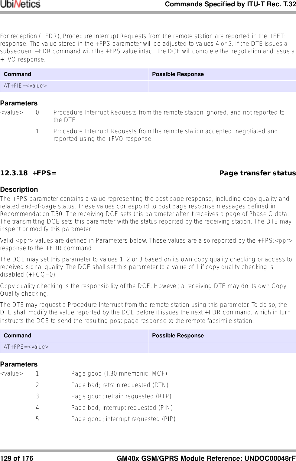
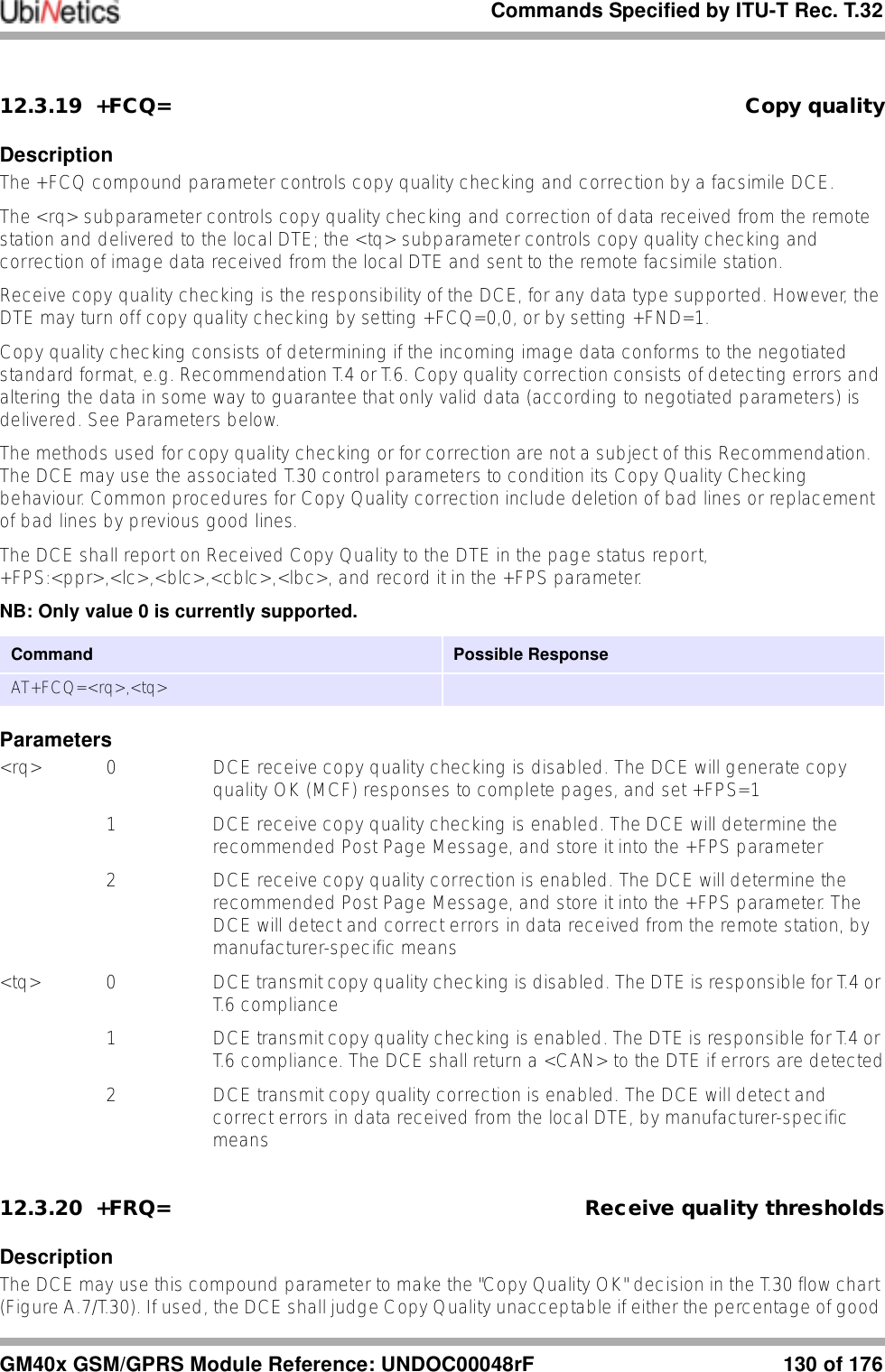
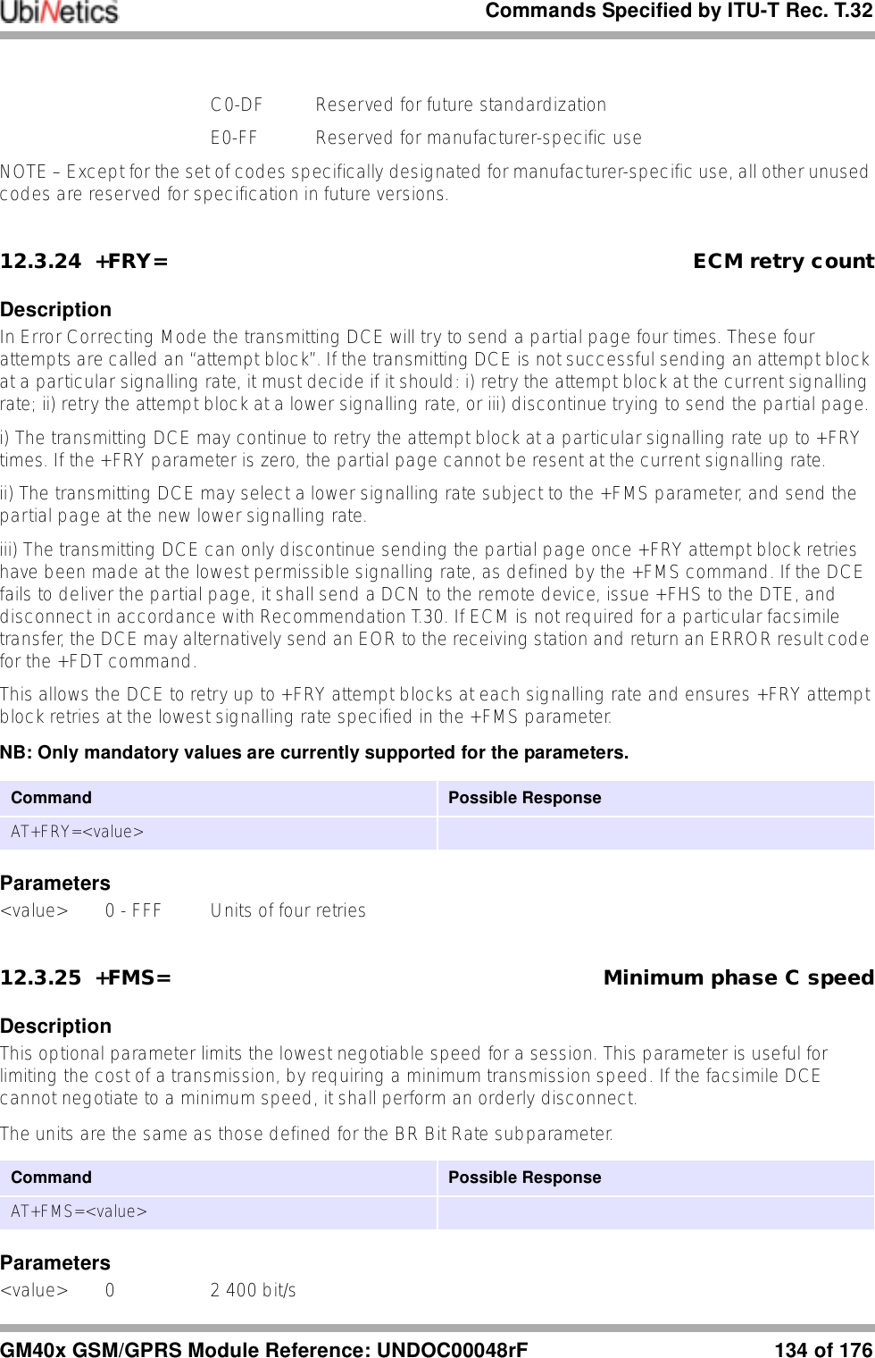
![Commands Specified by ITU-T Rec. T.32109 of 176 GM40x GSM/GPRS Module Reference: UNDOC00048rF12.0 Commands Specified by ITU-T Rec. T.3212.1 Action commands12.1.1 D Originate a callDescriptionInitiates a call or resumes a session after procedure interruption. If the <dial string> is terminated by a semi-colon, the DCE returns to command state while remaining off-hook.12.1.2 A Answer a callDescriptionThe DTE issues an A command in response to incoming Ringing.12.1.3 +FDT Send a pageDescriptionThe FDT command requests the DCE to transmit a Phase C page. It is issued at the beginning of each page, either in Phase B or in Phase D. When the DCE is ready to accept Phase C data, it issues the negotiation responses and the CONNECT result code to the DTE.12.1.4 +FDR Receive a pageDescriptionThe +FDR command initiates transition to Phase C data reception. This can occur after answering, after dialling, after a document is received, or after a page is received.Command Possible ResponseATD[<dial string>]<CR>ATD[<dial string>];<valid commands><CR>Command Possible ResponseATA<CR>Command Possible ResponseAT+FDT<CR>Command Possible ResponseAT+FDR<CR>](https://usermanual.wiki/Ubinetics/GM401.User-manual/User-Guide-233185-Page-114.png)
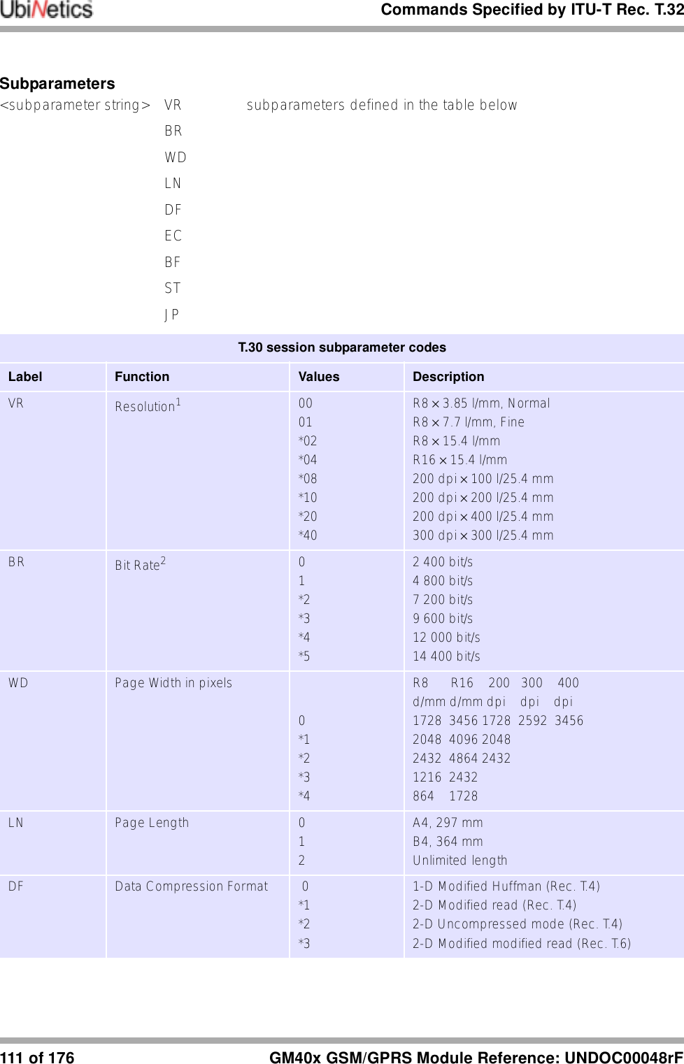
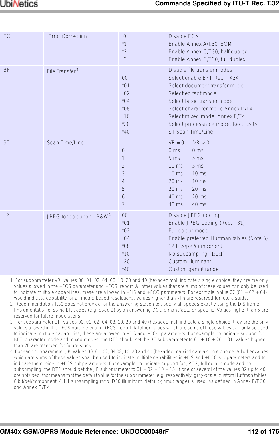
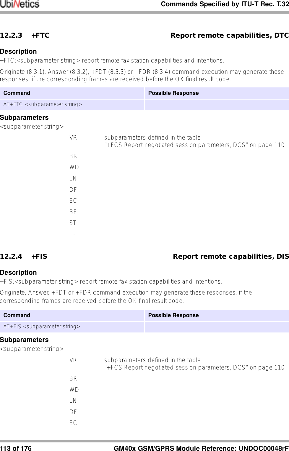
![Commands Specified by ITU-T Rec. T.32GM40x GSM/GPRS Module Reference: UNDOC00048rF 110 of 17612.1.5 +FKS Terminate a sessionDescriptionThe +FKS command causes the DCE to terminate the session in an orderly manner. In particular, it will send a DCN message at the next opportunity and hang up.12.1.6 +FIP Initialise Service Class 2 parametersDescriptionThe +FIP command causes the DCE to initialise all Service Class 2 Facsimile Parameters to the manufacturer-determined default settings. This command does not change the setting of +FCLASS. This command has the same effect as if the DTE had issued individual parameter setting commands.The optional subparameter <value> is a set of manufacturer-specified parameters.12.2 DCE responsesThe DCE sends information responses to the DTE as a fax session proceeds. They indicate the state of the fax session and convey needed information. These are solicited messages, generated in response to the DTE action commands described on page 109.12.2.1 +FCO Fax connectionDescriptionThe +FCO response indicates connection with a Group 3 facsimile station. 12.2.2 +FCS Report negotiated session parameters, DCSDescriptionReports negotiated parameters. Phase C data is formatted as reported by these subparameters. +FDT or +FDR command execution may generate these responses, before the CONNECT result code, if new DCS frames are generated or received.Command Possible ResponseAT+FKSCommand Possible ResponseAT+FIP[=<value>]Command Possible ResponseAT+FCS:<subparameter string>](https://usermanual.wiki/Ubinetics/GM401.User-manual/User-Guide-233185-Page-115.png)
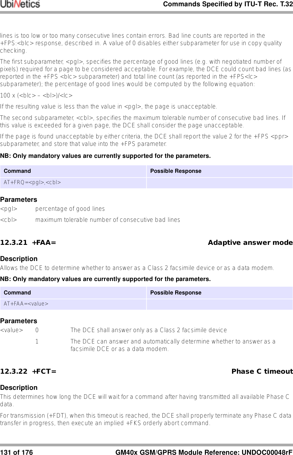
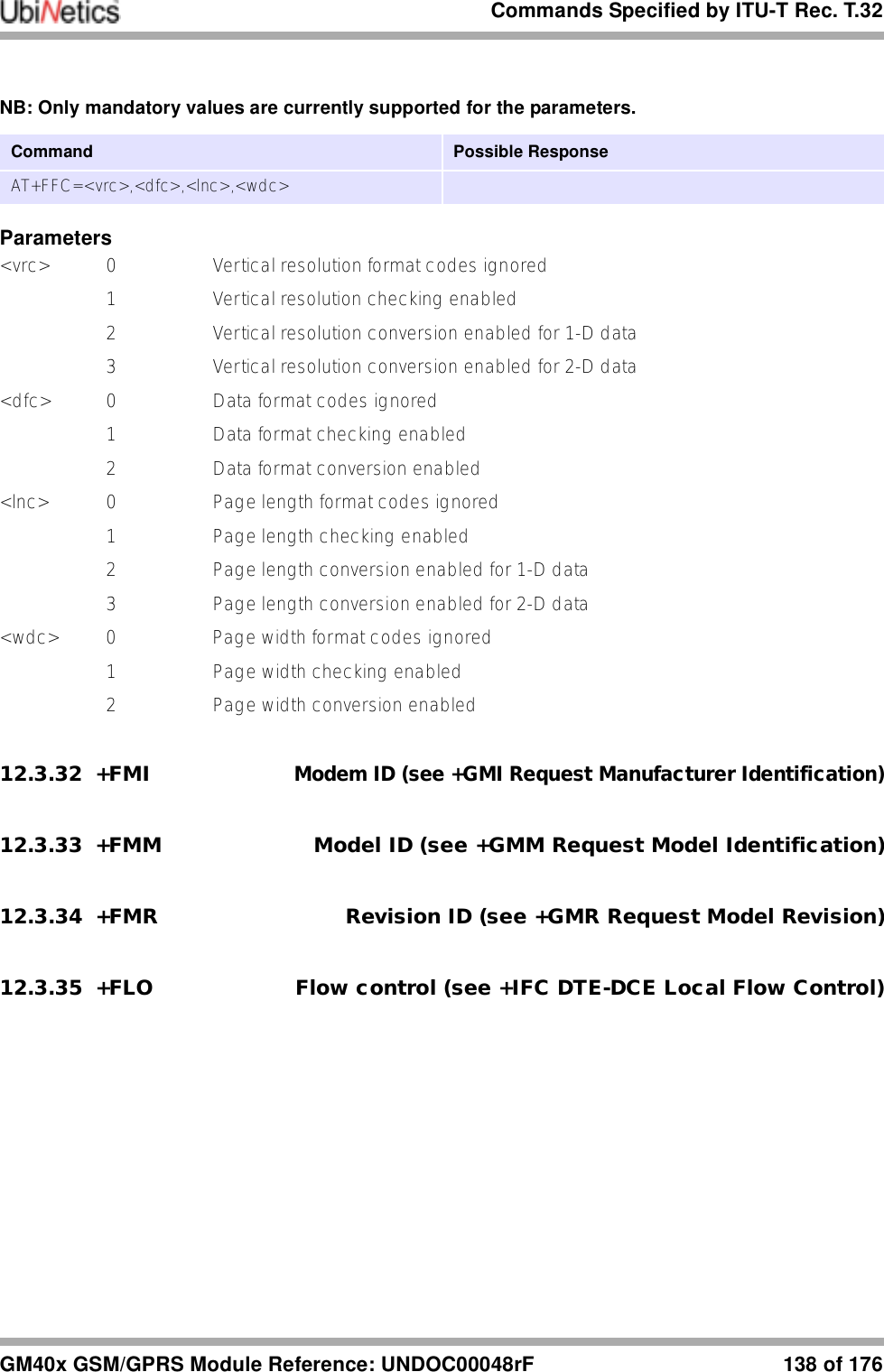
![Commands Specified by ITU-T Rec. T.32137 of 176 GM40x GSM/GPRS Module Reference: UNDOC00048rF1 Selects reversed bit order for Phase C data and selects direct bit order for Phase B/Ddata2 Selects direct bit order for Phase C data and selects reversed bit order for Phase B/Ddata3 Selects reversed bit order for both Phase C data and for Phase B/D data12.3.30 +FEA= Phase C received EOL alignmentDescriptionThis parameter enables optional octet-alignment of EOL markers in received T.4 data streams. It does not apply to T.6 data, or to any other form of data (e.g. T.434 BFT).As per 4.2.2/T.4, the tag bit for two dimensional coding, which indicates the coding used for the following line, shall be included in that line in the octet following the previous EOL.NB: Only mandatory values are currently supported for the parameters.Parameters<value> 0 Determines that T.4 EOL patterns are bit-aligned (as received)1 Determines that the last received bits of T.4 EOL patterns are octet-aligned by the DCE, with necessary zero fill bits inserted. There are two 2-octet patterns:+FBO= binary EOL pattern0 or 2 0000xxxx 100000001 or 3 xxxx0000 00000001xxxx represent previous data bits, zero bits, or other leadingdata.12.3.31 +FFC= Image data format conversionDescriptionThis compound parameter determines the DCE response to mismatches between the Phase C data delivered after the +FDT command and the data format parameters negotiated for the facsimile session. [See +FCS: response and +FCS parameter]For mismatch checking, the DCE depends on the DTE to indicate the data format with embedded <DLE><format> character pairs. If these format indicators are not provided, the DCE shall assume that the format is as negotiated for that session.For each subparameter, value 0 determines that mismatch checking is disabled, and all format codes of this type are ignored. Value 1 determines that mismatch checking is enabled, with session termination if the format codes do not match the negotiated format reported in +FCS: responses. Other values enable degrees of format conversion.Unspecified values are reserved.Command Possible ResponseAT+FEA=<value>](https://usermanual.wiki/Ubinetics/GM401.User-manual/User-Guide-233185-Page-142.png)
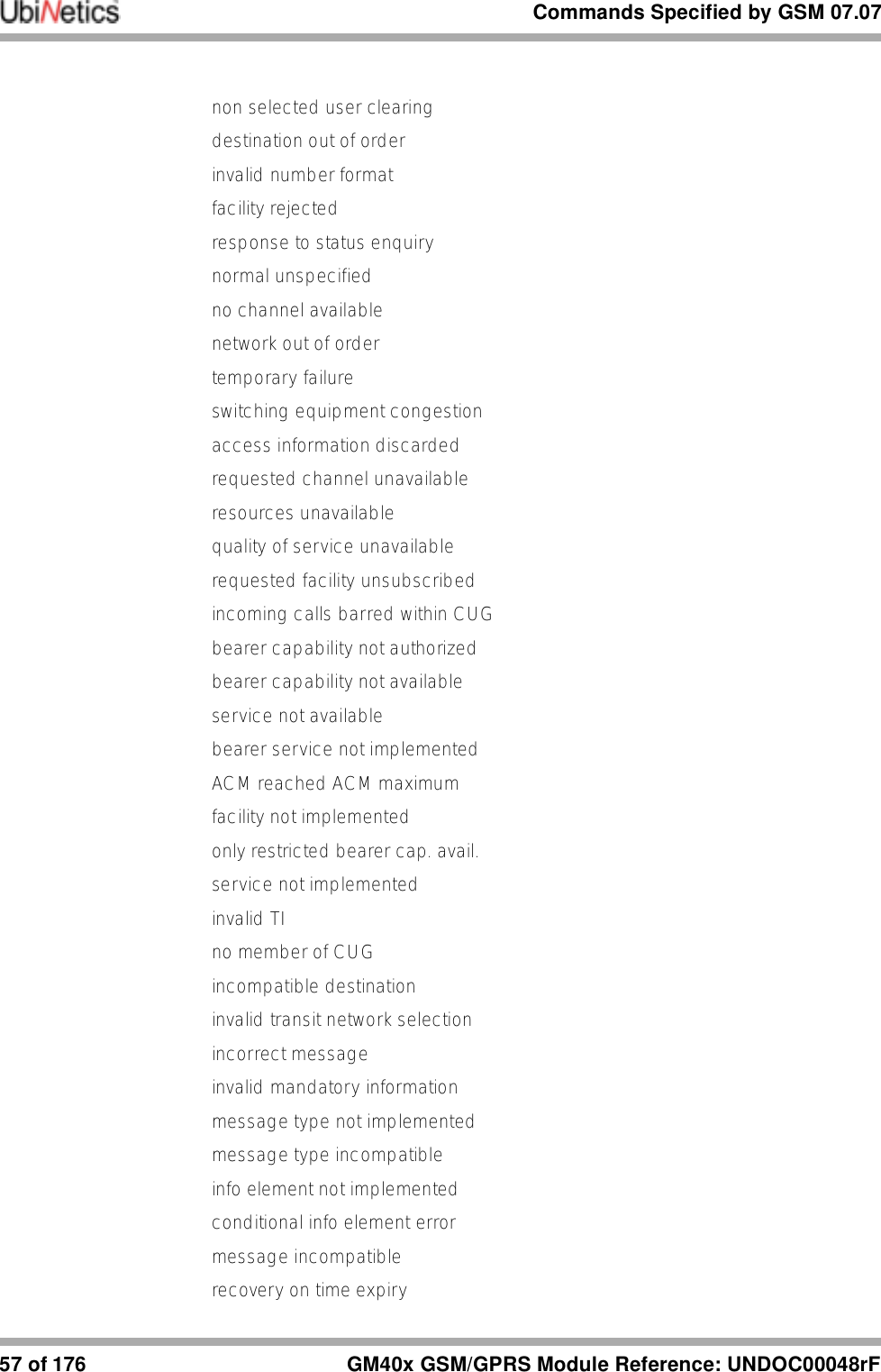
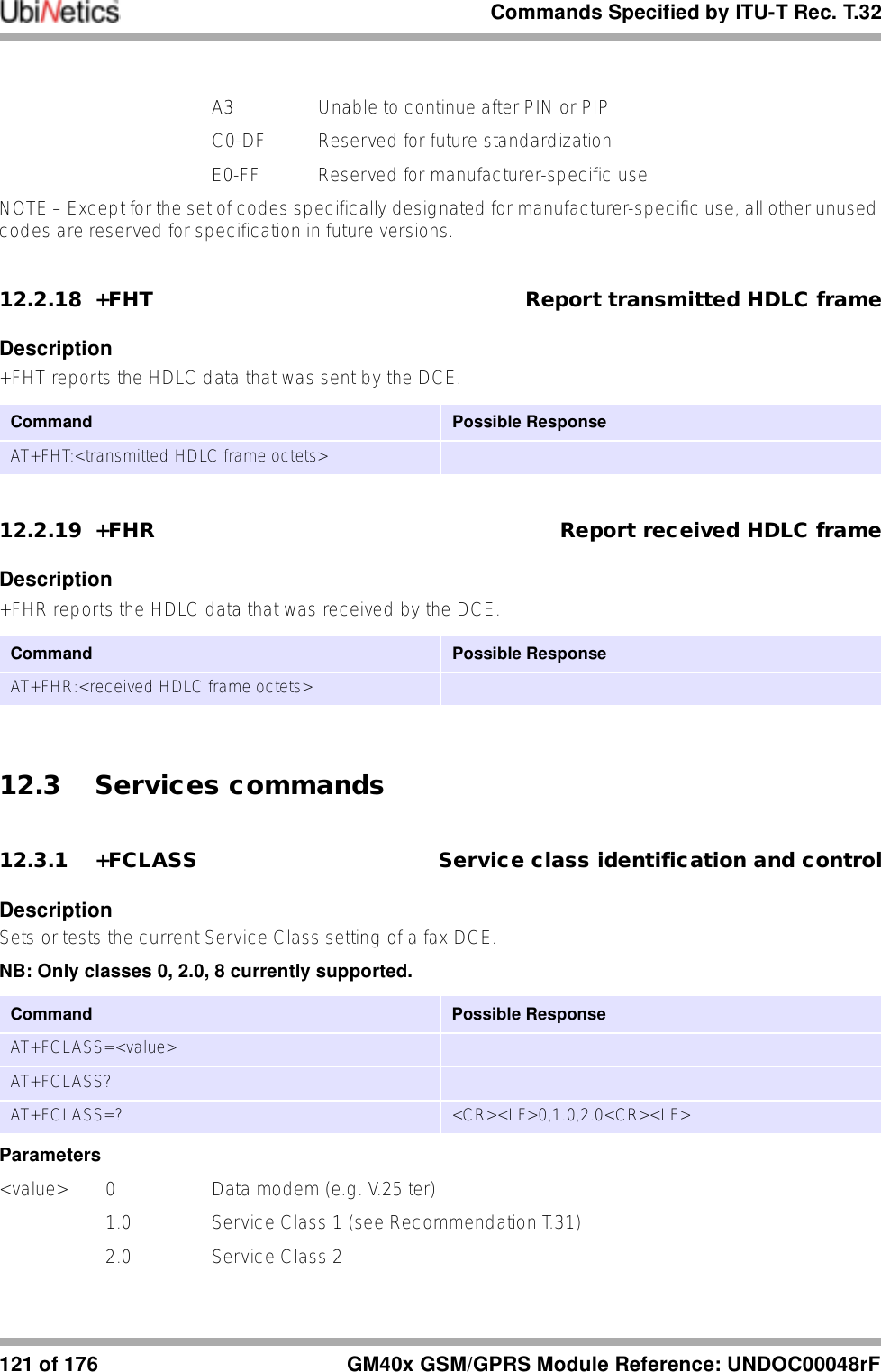
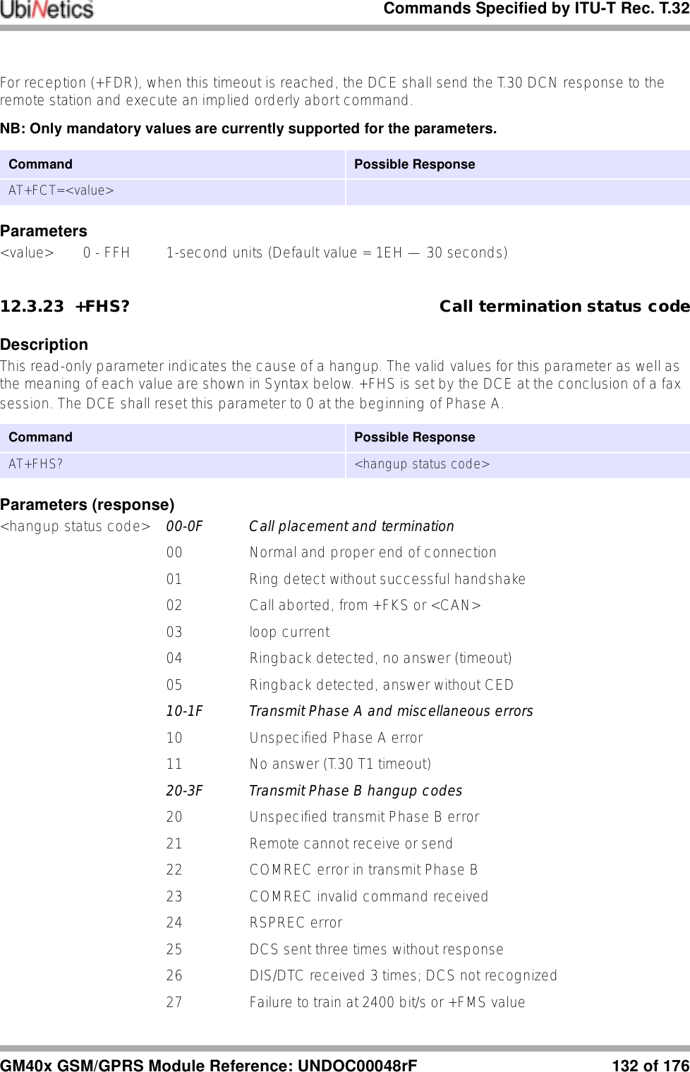
![Condat-specific commands139 of 176 GM40x GSM/GPRS Module Reference: UNDOC00048rF13.0 Condat-specific commands(Reproduced from Condat document “ACI - Application Control Interface, Condat Specific AT Command Description”, May 14, 2000. ID: 8415.052.00.003. Author: Condat AG, Alt Moabit 91d, 10559 Berlin, Germany. Reformatted by UbiNetics to be consistent with the rest of this Reference Manual. These command descriptions are reproduced here for the convenience of the reader; the Condat source document should be regarded as the authoritative source.)13.0.1 %NRG Network registration and service selectionDescriptionSet command forces an attempt to select and register the GSM network operator. <regMode> is used to select whether the selection is done automatically by the ME or is forced by this command to operator <opr> (it shall be given in format <oprFrmt>). If the selected operator is not available, no other operator is selected. The selected operator name format shall apply to further read commands (%NRG?) also. <srvMode> is used to specify the different stages of service to register to. <srvMode>=3 can be used to change the behavior of registration in case of a loss of coverage. If connection to the operator is lost and <regMode> was set to automatic, ME tries to register to the previous operator automatically. In case <regMode> was set to manual, ME stays unregistered and waits for a manual registration attempt. Refer subclause 9.2 of [GSM 07.07] for possible <err> values. This command is abortable when registration attempt is made.Read command returns the current registration mode, service mode, service status and the currently selected operator. If no operator is selected, <oprFrmt> and <opr> are omitted.Test command returns facility values supported by the TA as a compound value.NOTE: The command %NRG is an expansion of the +COPS command. The new command allows specifying the service state of the registration. For a list of current available network operators please use the test command of +COPS.Parameters<regMode> 0 automatic registration (<opr> field is ignored)1 manual registration (<opr> field shall be present on registration attempt)<srvMode> 0 full service1 limited service2 no service3 set registration mode only<oprFrmt> 0 long format alphanumeric <opr>Command Possible responseAT%NRG=? %NRG: (list of supported <regMode>s), (list of supported<srvMode>s), (list of supported <oprFrmt>s)AT%NRG? %NRG: <regMode>,<srvMode>,<oprFrmt>,<srvStat>,<opr>AT%NRG=[<regMode>[,<srvMode>[,<oprFrmt>[,<opr>]]]] +CME ERROR: <err>](https://usermanual.wiki/Ubinetics/GM401.User-manual/User-Guide-233185-Page-144.png)
![Condat-specific commandsGM40x GSM/GPRS Module Reference: UNDOC00048rF 140 of 1761 short format alphanumeric <opr>2 numeric <oprr><opr> string type; <oprFrmt> indicates if the format is alphanumeric or numeric; long alphanumeric format can be up to 16 characters long and short format up to 8 characters; numeric format is the GSM Location Area Identification number (refer GSM 04.08 subclause 10.5.1.3) which consists of a three BCD digit country code coded as in ITU-T E.212 Annex A, plus a two BCD digit network code, which is administration specific; returned <opr> shall not be in BCD format, but in IRA characters converted from BCD; hence the number has structure: (country code digit 3)(country code digit 2)(country code digit 1)(network code digit 2)(network code digit 1)13.0.2 %CACM Query accumulated call meter using PUCTDescriptionReturns the current value of the accumulated call meter, calculated with the values given by the price per unit andcurrency table stored in SIM. Refer subclause 9.2 of [GSM 07.07] for possible <err> values.Parameters<cur> string type three-character currency code (e.g. "GBP", "DEM"); character set as specified by command Select TE Character Set +CSCS<price> string type calculated price value of accumulated call meter; dot is used as a decimal separator (e.g. "2.66")13.0.3 %CAOC Query current call meter using PUCTDescriptionReturns the current value of the current call meter, calculated with the values given by the price per unit and currency table stored in SIM. Refer subclause 9.2 of [GSM 07.07] for possible <err> values.Parameters<cur> string type three-character currency code (e.g. "GBP", "DEM"); character set as specified by command Select TE Character Set +CSCS<price> string type calculated price value of accumulated call meter; dot is used as a decimal separator (e.g. "2.66")Command Possible responseAT%CACM=?AT%CACM %CACM: <cur>,<price>+CME ERROR: <err>Command Possible response(s)AT%CAOC %CAOC: <cur>,<price>+CME ERROR: <err>AT%CAOC=?](https://usermanual.wiki/Ubinetics/GM401.User-manual/User-Guide-233185-Page-145.png)
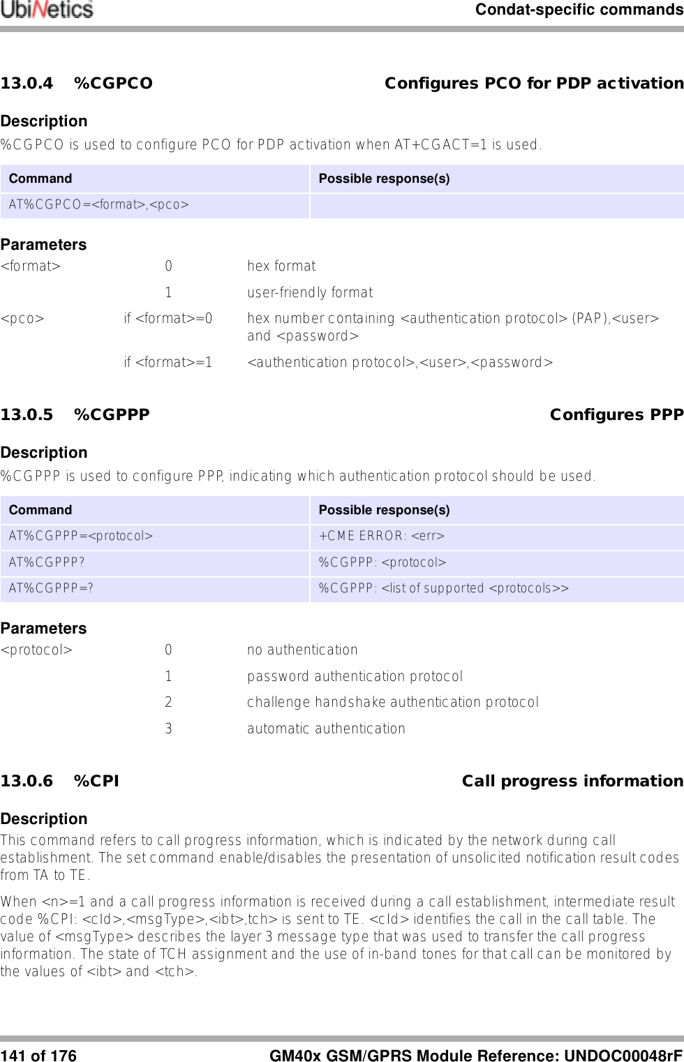
![Condat-specific commandsGM40x GSM/GPRS Module Reference: UNDOC00048rF 142 of 176Test command returns values supported by the TA as compound value.Parameters<n> parameter sets/shows the result code presentation status in the TA0 disable1 enable<cId> integer type call identification number as described in GSM 02.30 subclause 4.5.5.1<msgType> layer 3 message type0 setup message1 disconnect message2 alert message3 call proceed message4 synchronization message<ibt> status of the usage of in-band tones0 no in-band tones1 in-band tones<tch> TCH assignment0 TCH not assigned1 TCH assigned13.0.7 %CTV Call timer valueDescriptionReturns the current value of the last call duration in seconds. Refer subclause 9.2 of [GSM 07.07] for possible <err>values.Parameters<dur> integer type represents the duration of the last call in unit of secondsCommand Possible response(s)AT%CPI=? %CPI: (list of supported <n>s)AT%CPI? %CPI: <n>AT%CPI=<n>Command Possible response(s)AT%CTV=?AT%CTV %CTV: <dur> +CME ERROR: <err>](https://usermanual.wiki/Ubinetics/GM401.User-manual/User-Guide-233185-Page-147.png)
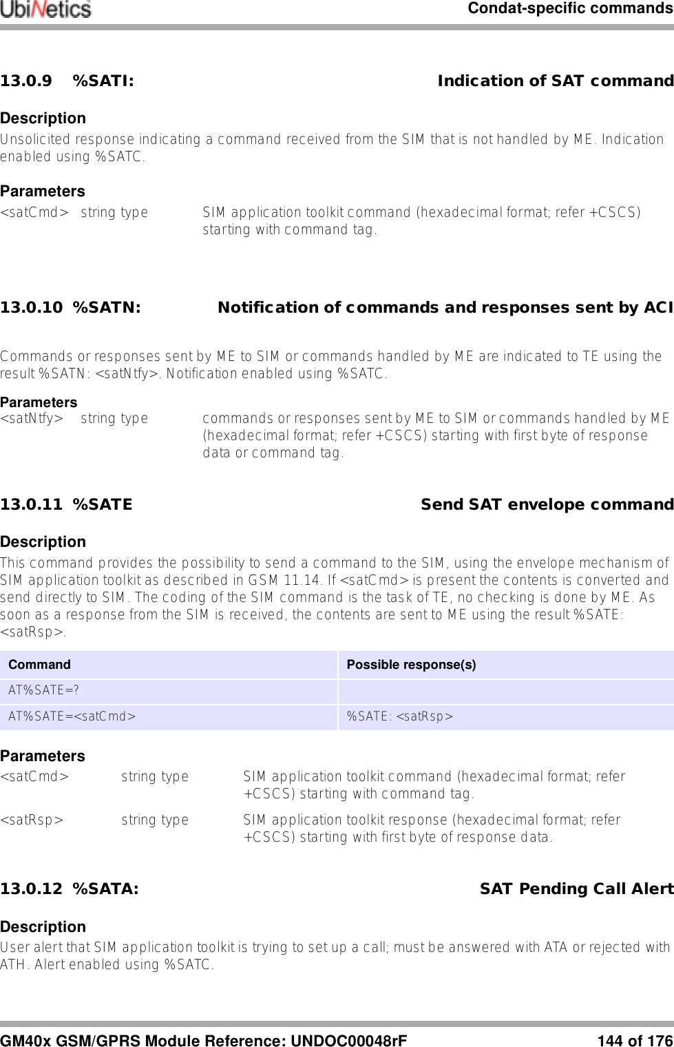
![Condat-specific commands143 of 176 GM40x GSM/GPRS Module Reference: UNDOC00048rF13.0.8 %SATC Configuration for SIM application toolkitDescriptionThis command refers to the SIM application toolkit download mechanism, which is used to indicate to the SIM the features that the ME is capable of. The different features that are possible for a proactive SIM card are summarized by a table called a profile, refer to GSM 11.14 for more details. Condat's ACI, SMS and SIM modules already implement some of these features. Therefore the profile that is indicated by <satPrfl> will be combined with the existing one.The current profile setting could be displayed using the read command. <n> is used to enable/disable the presentation of unsolicited notification result codes from TA to TE.When <n>=1 and one of the following conditions have occurred, the respective unsolicited result is sent to TE.●A command received from the SIM that is not handled by ME is indicated to TE by %SATI: <satCmd>.●The result to an envelope command, which was sent by TE, is indicated using the result %SATE: <satRsp>. For more information regarding the sending of envelope commands to SIM, please refer to the %SATE command description.●If SIM application toolkit tries to set up a call using the Set Up Call feature described in GSM 11.14, and the conditions for the call are checked by ME successfully, the call is indicated to TE using the result %SATA: [<rdl>]. Using the accept command A, ME tries to establish the call, otherwise the hook-on command H rejects the pending SAT call and sends the respective response to SIM.●In general, commands or responses sent by ME to SIM or commands handled by ME are indicated to TE using the result %SATN: <satNtfy>. With these notifications, TE shall be able to indicate appropriate messages to a user.Parameters<n> parameter sets/shows the result code presentation status in the TA0 disable notification1 enable notification<satPrfl> string type SIM application toolkit profile (hexadecimal format; refer +CSCS) starting with first byte of the profile.<satCmd> string type SIM application toolkit command (hexadecimal format; refer +CSCS) starting with command tag.<satRsp> string type SIM application toolkit response (hexadecimal format; refer +CSCS) starting with first byte of response data.<satNtfy> string type commands or responses sent by ME to SIM or commands handled by ME (hexadecimal format; refer +CSCS) starting with first byte of response data or command tag.<rdl> integer type if a pending SIM application toolkit command is alerted to TE using result %SATA:, the value of <rdl> indicates the redial timeout for the call in units of milliseconds.Command Possible responseAT%SATC=? %SATC: (list of supported <n>s),(<prflLen>)AT%SATC? %SATC: <n>,<satPrfl>AT%SATC=<n>,<satPrfl>](https://usermanual.wiki/Ubinetics/GM401.User-manual/User-Guide-233185-Page-148.png)
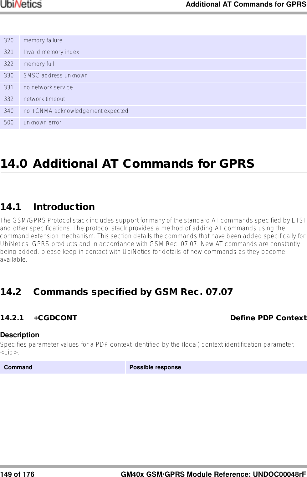
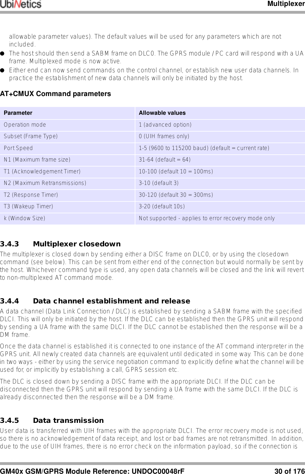
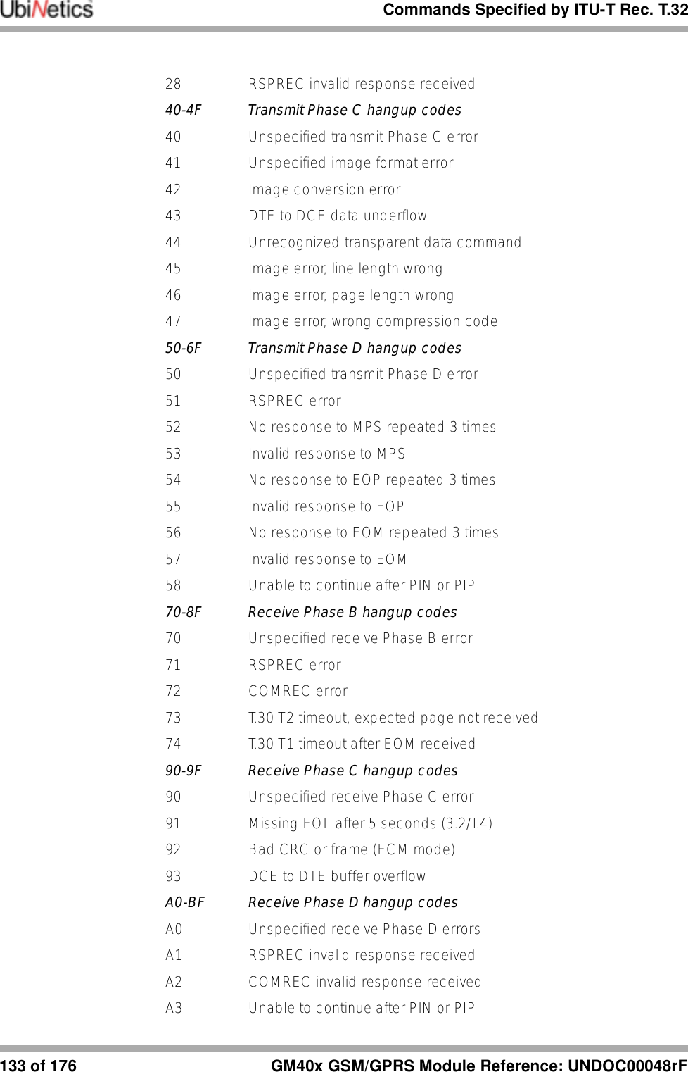
![Additional AT Commands for GPRSGM40x GSM/GPRS Module Reference: UNDOC00048rF 150 of 176Parameters<cid> PDP Context Identifier Range of permitted values returned by the test form of the command<PDP_type> Packet Data Protocol typeIP Internet Protocol (IETF STD 5)<APN> Access Point Name; a string parameter which is a logical name used to select the GGSN or the external packet data network.<PDP_address> String parameter that identifies the MT in the address space applicable to the PDP. The allocated address may be read using the +CGPADDR command.<d_comp> Numeric parameter that controls PDP data compression0 Off (default if value is omitted)1OnOther values are reserved.<h_comp> Numeric parameter that controls PDP header compression0 Off (default if value is omitted)1OnOther values are reserved.<pd1>,…<pdN> Zero to N string parameters whose meanings are specific to the <PDP_type>For PDP type OSP:IHOSS the following parameters are defined:<pd1> = <host> the fully formed domain name extended hostname of the Internet host<pd2> = <port > the TCP or UDP port on the Internet host<pd3> = <protocol> the protocol to be used over IP on the Internet - "TCP" or "UDP”AT+CGDCONT=? +CGDCONT: (range of supported <cid>s),<PDP_type>,,,(list of supported <d_comp>s),(list of supported <h_comp>s)[,(list of supported<pd1>s)[,…[,(list of supported <pdN>s)]]][<CR><LF>+CGDCONT: (range of supported <cid>s),<PDP_type>,,,(list of supported <d_comp>s),(list of supported <h_comp>s)[,(list of supported<pd1>s)[,…[,(list of supported <pdN>s)]]][...]]AT+CGDCONT? +CGDCONT: <cid>, <PDP_type>,<APN>,<PDP_addr>, <data_comp>,<head_comp>[,<pd1>[,…[,pdN]]][<cr><lf>+CGDCONT: <cid>, <PDP_type>,<APN>,<PDP_addr>, <data_comp>,<head_comp>[,<pd1>[,…[,pdN]]][...]]AT+CGDCONT=[<cid> [,<PDP_type> [,<APN>[,<PDP_addr> [<d_comp> [,h_comp>[,<pd1> [,…[,pdN]]]]]]]]]](https://usermanual.wiki/Ubinetics/GM401.User-manual/User-Guide-233185-Page-155.png)
![Additional AT Commands for GPRS151 of 176 GM40x GSM/GPRS Module Reference: UNDOC00048rF14.2.2 +CGQREC Quality of Service Profile (requested)DescriptionAllows the DTE to specify a Quality of Service Profile that is used when the MT sends an Activate PDP Context Request message to the network.If no Profile exists, an error will be returned.Parameters<cid> Numeric parameter specifying a particular PDP context definition (see AT+CGDCONT command).Parameters defined in GSM 03.60:<precedence> Numeric parameter specifying the precedence class<delay> Numeric parameter specifying the delay class<reliability> Numeric parameter specifying the reliability class<peak> Numeric parameter specifying the peak throughput class<mean> Numeric parameter specifying the mean throughput classIf a value is omitted for a particular class, the value is considered to be unspecified.14.2.3 +CGQMIN Quality of Service Profile (minimum accepted)DescriptionAllows the DTE to specify a minimum acceptable profile which is checked by the MT against the negotiated profile returned in the Activate PDP Context Accept message.Command Possible responseAT+CGQREQ=? +CGQREQ: <PDP_type>, (list of supported <precedence>s), (list of supported <delay>s), (list of supported <reliability>s) , (list of supported <peak>s), (list of supported <mean>s) [<CR><LF>+CGQREQ: <PDP_type>, (list of supported <precedence>s), (list of supported <delay>s), (list of supported<reliability>s) , (list of supported <peak>s), (list of supported <mean>s) […]]AT+CGQREQ? +CGQREQ: <cid>, <precedence >, <delay>, <reliability>, <peak>, <mean>[<CR><LF>+CGQREQ: <cid>, <precedence >,<delay>, <reliability.>, <peak>, <mean>[…]]AT+CGQREQ=[<cid> [,<precedence > [,<delay>[,<reliability.> [,<peak> [,<mean>]]]]]]](https://usermanual.wiki/Ubinetics/GM401.User-manual/User-Guide-233185-Page-156.png)
![Additional AT Commands for GPRSGM40x GSM/GPRS Module Reference: UNDOC00048rF 152 of 176Parameters<cid> Numeric parameter specifying a particular PDP context definition (see +CGDCONT command).Parameters defined in GSM 03.60:<precedence> Numeric parameter specifying the precedence class<delay> Numeric parameter specifying the delay class<reliability> Numeric parameter specifying the reliability class<peak> Numeric parameter specifying the peak throughput class<mean> Numeric parameter specifying the mean throughput classIf a value is omitted for a particular class, the value is considered to be unspecified.14.2.4 +CGATT GPRS Attach or DetachDescriptionAttach the MT to, or detach the MT from, the GPRS service.Parameters<state> 0 detached1attachedCommand Possible responseAT+CGQMIN=? +CGQMIN: <PDP_type>, (list of supported <precedence>s), (list of supported <delay>s), (list of supported <reliability>s) , (list of supported <peak>s), (list of supported <mean>s) [<CR><LF>+CGQMIN: <PDP_type>, (list of supported <precedence>s), (list of supported <delay>s), (list of supported<reliability>s) , (list of supported <peak>s), (list of supported <mean>s) […]]AT+CGQMIN? +CGQMIN: <cid>, <precedence >, <delay>, <reliability>, <peak>, <mean> [<CR><LF>+CGQMIN: <cid>, <precedence >,<delay>, <reliability.>, <peak>, <mean> […]]AT+CGQMIN=[<cid> [,<precedence > [,<delay> [,<reliability.> [,<peak> [,<mean>]]]]]]Command Possible responseAT+CGATT=? +CGATT:(list of supported <state>s)AT+CGATT? +CGATT:<state>AT+CGATT=[<state>]](https://usermanual.wiki/Ubinetics/GM401.User-manual/User-Guide-233185-Page-157.png)
![Additional AT Commands for GPRS153 of 176 GM40x GSM/GPRS Module Reference: UNDOC00048rF14.2.5 +CGACT PDP Context Activate or DeactivateDescriptionActivate or deactivate the specified PDP context (s).Parameters<state> the state of PDP context activation0 Deactivated1 Activated<cid> Numeric parameter specifying a particular PDP context definition (see +CGDCONTcommand).14.2.6 +CGDATA Enter Data StateDescriptionCauses the MT to try to establish communication between the DTE and the network, using one or more PDP types. Parameters<L2P> String parameter indicating the layer 2 protocol to be used between the DTE and MT. If omitted, the layer 2 protocol is unspecified. PPP Point-to-point protocol for a PDP such as IP<cid> Numeric parameter which specifies a particular PDP context definition (see AT+CGDCONT).14.2.7 +CGPADDR Show PDP AddressDescriptionReturns a list of PDP addresses for the specified context identifiers.Command Possible responseAT+CGACT=? +CGACT: (list of supported <state>s)AT+CGACT? +CGACT: <cid>, <state>[<CR><LF>+CGACT: <cid>, <state>[...]]AT+CGACT=[<state> [,<cid>[,<cid>[,…]]]]Command Possible responseAT+CGDATA=? +CGDATA: (list of supported <L2P>s)AT+CGDATA=[<L2P> ,[<cid> [,<cid> [,…]]]]](https://usermanual.wiki/Ubinetics/GM401.User-manual/User-Guide-233185-Page-158.png)
![Additional AT Commands for GPRSGM40x GSM/GPRS Module Reference: UNDOC00048rF 154 of 176Parameters<cid> Numeric parameter specifying a particular PDP context definition (see +CGDCONT). If no <cid> is specified, the addresses for all defined contexts are returned.<PDP_address> String identifying the MT in the address space applicable to the PDP. The address may be static or dynamic: a static address is the one set by the +CGDCONT command when the context was defined; a dynamic address is the one assigned during the last PDP context activation that used the context definition referred to by <cid>. 14.2.8 +CGAUTO Automatic Response to PDP Context Activation RequestDescriptionDisables or Enables auto-answer to the receipt of a Request PDP Context Activation message from the network.Parameters<n> 0 Turn off automatic response for GPRS only1 Turn on automatic response for GPRS only2 Modem compatibility mode, GPRS only3 Modem compatibility mode, GPRS and circuit switched calls14.2.9 +CGANS Manual Response to PDP Context Activation RequestDescriptionRequests the MT to respond to a network request for GPRS PDP context activation signalled to the DTE by the RING or +CRING: unsolicited result code. The DTE can accept or reject the request.Command Possible responseAT+CGPADDR=? +CGPADDR=?AT+CGPADDR=[<cid> [,<cid>[,…]]] +CGPADDR:<cid>,<PDP_addr>[<CR><LF>+CGPADDR:<cid>,<PDP_addr>[...]]Command Possible responseAT+CGAUTO=? +CGAUTO: (list of supported <n>s)AT+CGAUTO? +CGAUTO:<n>AT+CGAUTO=[<n>]](https://usermanual.wiki/Ubinetics/GM401.User-manual/User-Guide-233185-Page-159.png)
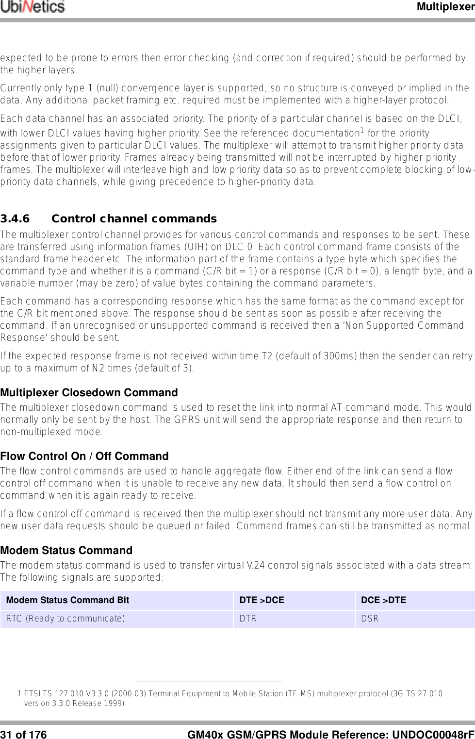
![Additional AT Commands for GPRS155 of 176 GM40x GSM/GPRS Module Reference: UNDOC00048rFParameters<response> Numeric parameter specifying how to respond to the request. If <response> is omitted, it is assumed to be 00 Reject the request1 Accept, and request that the PDP context be activated<L2P> Layer 2 protocol to be used (PPP)<cid> Numeric parameter specifying a particular PDP context definition (see +CGDCONT).14.2.10 +CGCLASS GPRS Mobile Station ClassDescriptionSets the MT to operate according to the specified GPRS mobile class.Parameters<class> String parameter indicating the GPRS mobile classB Class BC Class C in GPRS and circuit switched alternate modeCG Class C in GPRS-only modeCC Class C in circuit switched only mode (lowest)14.2.11 +CGEREP GRS Event ReportingDescriptionEnables or disables sending +CGEV: xxx unsolicited result codes from the MT to the DTE following certain events occurring in the MT or the network.Command Possible responseAT+CGANS=? +CGANS: (list of supported<response>s), (list of supported<L2P>s)AT+CGANS=[<response>,[<L2P> ,[<cid>]]]Command Possible responseAT+CGCLASS=? +CGCLASS: (list of supported <class>s)AT+CGCLASS? +CGCLASS: <class>AT+CGCLASS= [<class>]](https://usermanual.wiki/Ubinetics/GM401.User-manual/User-Guide-233185-Page-160.png)
![Additional AT Commands for GPRSGM40x GSM/GPRS Module Reference: UNDOC00048rF 156 of 176Parameters<mode> 0 MT buffers unsolicited result codes1 Discards unsolicited result codes when in on-line data mode (MT-TE link reserved), otherwise forward them directly to the DTE2 Buffers unsolicited result codes in the MT when in on-line data mode and flushes them to the DTE when MT- DTE link becomes available; otherwise forwards them directly to the DTE<bfr> 0 The MT unsolicited result codes buffer, defined within this command, is cleared on entering <mode> 1 or 21 MT unsolicited result codes buffer, defined within this command, flushed to the DTE on entering <mode> 1 or 2.14.2.12 +CGREG GPRS Network Registration StatusDescriptionControls the presentation of a GPRS MT’s network status.Parameters<n> 0 Disable network registration unsolicited result code1 Enable network registration unsolicited result code +CGREG: <stat><stat> 0 Not registered: mobile not searching a new operator to register with1 Registered, home network2 Not registered, but mobile searching for a new operator to register with3 Registration denied4 Unknown5 Registered, roamingCommand Possible responseAT+CGEREP=? +CGEREP: (list of supported <mode>s), (list of supported <bfr>s)AT+CGEREP? +CGEREP: <mode>,<bfr>AT+CGEREP=[<mode>[,<bfr>]]Command Possible responseAT+CGREG=? +CGREG: (list of supported <n>s)AT+CGREG? +CGREG: <n>,<stat>AT+CGREG=[<n>]Unsolicited Result Code +CGREG: <stat>](https://usermanual.wiki/Ubinetics/GM401.User-manual/User-Guide-233185-Page-161.png)
![Additional AT Commands for GPRS157 of 176 GM40x GSM/GPRS Module Reference: UNDOC00048rF14.2.13 +CGSMS Select Service for MO SMS MessagesDescriptionSpecifies the MO SMS message service required.Parameters<service> Numeric parameter indicating the service or service preference to be used:0 GPRS1 Circuit-switched2 GPRS preferred (use circuit-switched if GPRS not available)3 Circuit-switched preferred (use GPRS if circuit-switched not available)14.2.14 D Request GPRS ServiceDescriptionCauses the ME to carry out any actions necessary to establish communication between the DTE and the external PDN.Parameters<GPRS_SC> 99 Request to use the GPRS<called_address> String identifying the called party in the address space applicable to the PDP. For communications software that does not support arbitrary characters in the dial string, a numeric equivalent may be used. The comma character ',' may be used as a substitute for the period character '.'.For PDP type OSP:IHOSS, the following syntax may be used:[<host>][@[<port>][@[<protocol>]]]For a definition of <host>, <port> and <protocol> , see +CGDCONT. For communications software that does not support arbitrary characters in the dial string, a numeric equivalent to the hostname may be used, but this should be avoided if at all possible.<L2P> String indicating the layer 2 protocol to be used (see +CGDATA). For communications software that does not support arbitrary characters in the dial string, the following numeric equivalents shall be used:1 PPPCommand Possible responseAT+CGSMS=? +CGSMS:(list of currently available <service>s)AT+CGSMS? +CGSMS: <service>AT+CGSMS=[<service>]Command Possible responseATD*<GPRS_SC>[*[<called_address>][*[<L2P>][*[<cid>]]]]#](https://usermanual.wiki/Ubinetics/GM401.User-manual/User-Guide-233185-Page-162.png)
![Additional AT Commands for GPRSGM40x GSM/GPRS Module Reference: UNDOC00048rF 158 of 176Note: V.250 (and some communications software) does not permit arbitrary characters in the dial string. The <L2P> and <called_address> strings are therefore specified as containing digits only.<cid> Digit string specifying a particular PDP context definition (see +CGDCONT).14.2.15 D Request GPRS IP ServiceDescriptionCauses the ME to carry out any actions necessary to establish communication between the DTE and the external PDN.Parameters<GPRS_SC_IP> 98 Request to use the GPRS<cid> Digit string specifying a particular PDP context definition (see +CGDCONT).14.2.16 SO Automatic Response to PDP Context Activation RequestDescriptionTurns off and on the automatic response to a request from the network for a PDP context activation.Parameters<value> 0 Off>0 On14.2.17 A Manual Acceptance of PDP Context Activation RequestDescriptionAccepts a request from the network for a PDP context activation (announced by the unsolicited result code RING). See also AT+CGANS.14.2.18 H Manual Rejection of PDP Context Activation RequestDescriptionRejects a request from the network for PDP context activation (announced by the unsolicited result code RING).Command Possible responseATD*<GPRS_SC_IP>[*<cid>]#Command Possible responseATSO=<value>Command Possible responseATA](https://usermanual.wiki/Ubinetics/GM401.User-manual/User-Guide-233185-Page-163.png)
![Additional AT Commands for GPRS159 of 176 GM40x GSM/GPRS Module Reference: UNDOC00048rF14.3 UbiNetics General Purpose CommandsThis section defines the general purpose commands that are supported by the product for general use.14.3.1 +ADC ADC ControlDescriptionThis command returns a single ADC value.Notes●Currently only ADC 0 (battery voltage) and ADC 6 (RF temperature) are used.●If the <type> parameter is 0 (or omitted) then the raw 10-bit ADC value is reported in hexadecimal.●If the <type> parameter is 1 then a converted value is reported in decimal; this is in mV for the battery voltage and °C for the RF temperature. ●Invalid parameter values or an invalid number of parameters will result in an ERROR return.ParametersSet parameters:<adc> ADC number in the range of 0 to 8<type> ADC conversion type (If omitted then a default of 0 is used)0 Raw 10-bit ADC1 Decimal Return values:Raw conversions a hexadecimal number in the range 0 to 3FFConverted values depends on the ADC selected and the conversion performedExamplesRead the RF temperature in °C:AT+ADC=6,1+ADC: 28OKCommand Possible responseATH [<value>]H0Command Possible responseAT+ADC=<adc>[,<type>] <value>](https://usermanual.wiki/Ubinetics/GM401.User-manual/User-Guide-233185-Page-164.png)
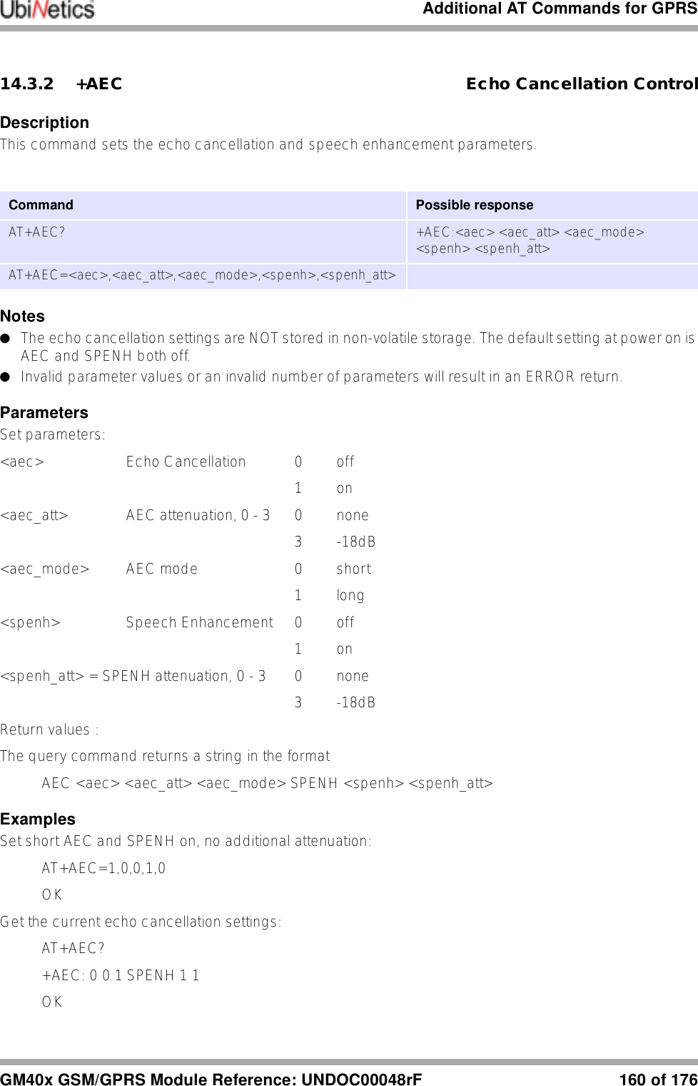
![Additional AT Commands for GPRS161 of 176 GM40x GSM/GPRS Module Reference: UNDOC00048rF14.3.3 +AUDIO Audio Path ControlDescriptionThis command sets or gets the state of the audio path switch. The audio can be switched to the main or auxiliary path. Optionally the audio power can be enabled or disabled; this allows audio loopback tests to be performed when not in call.Notes●The audio switch controls both microphone and ear-piece audio paths, setting the same audio path for both devices. It is not possible to select the main ear-piece and the auxiliary microphone, or vice versa.●Invalid parameter values or an invalid number of parameters will result in an ERROR return.●The audio settings are NOT stored in non-volatile storage. The default setting at power on is the main audio path selected, and audio power disabled.●If the power parameter is omitted then the audio power state is not changed.Parameters<path> 1 Auxiliary path2 Main path<power> 0 Audio power off1 Audio power onExamplesSet the audio path to select the main microphone and ear-piece:AT+AUDIO=2OKGet the current audio path:AT+AUDIO?+AUDIO: 2OKEnable loopback test using the main microphone and ear-piece:AT+AUDIO=2,1OK14.3.4 +AUXIN_GAIN AUX IN gain controlDescriptionThis command is used to set the auxiliary input amplifier gain.Command Possible responseAT+AUDIO? +AUDIO:<path>AT+AUDIO=<path>[,<power>]](https://usermanual.wiki/Ubinetics/GM401.User-manual/User-Guide-233185-Page-166.png)
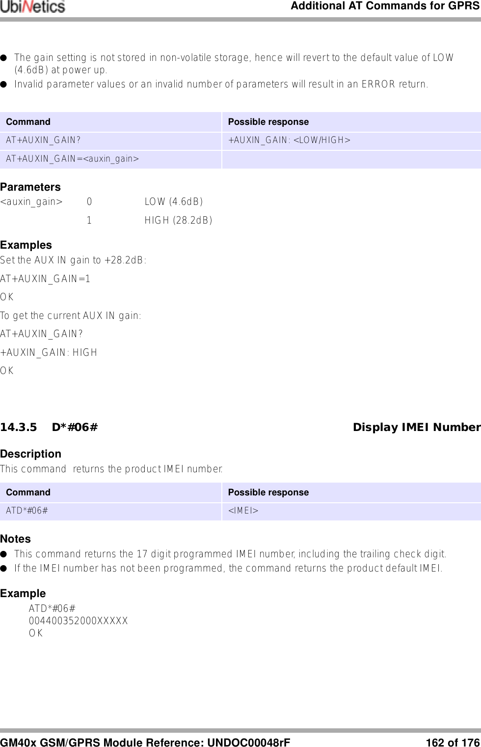
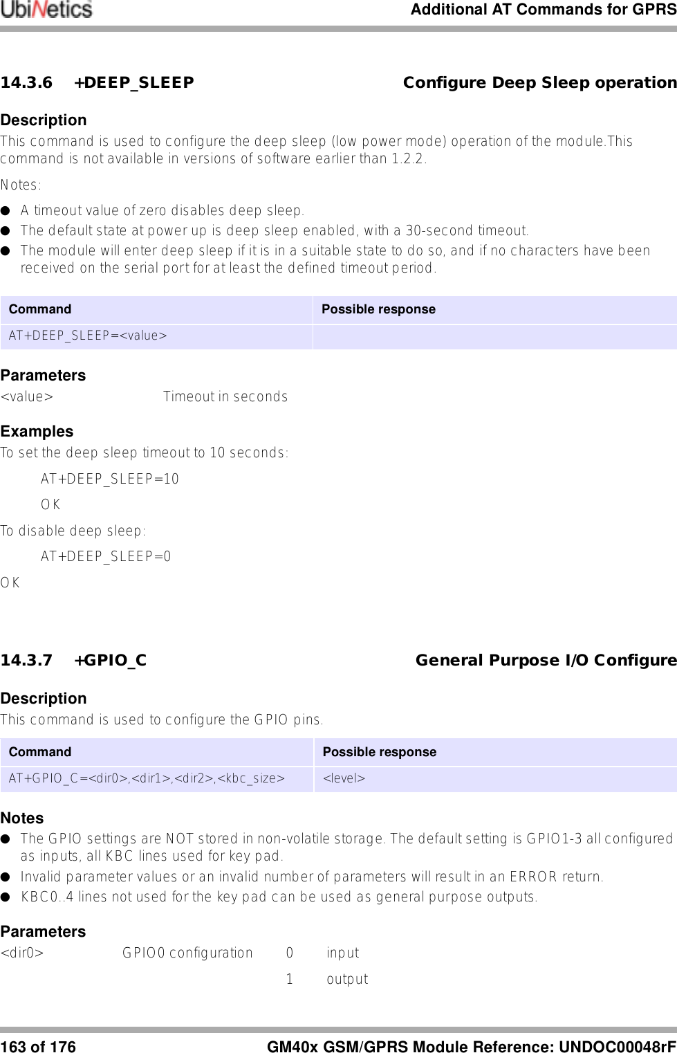
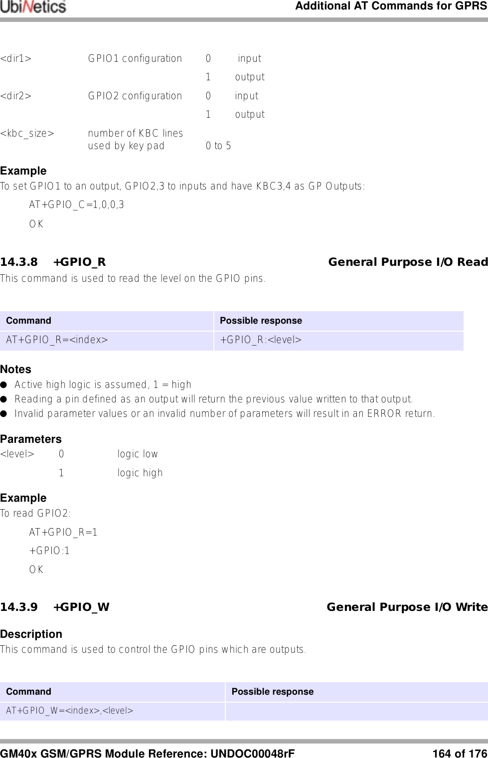
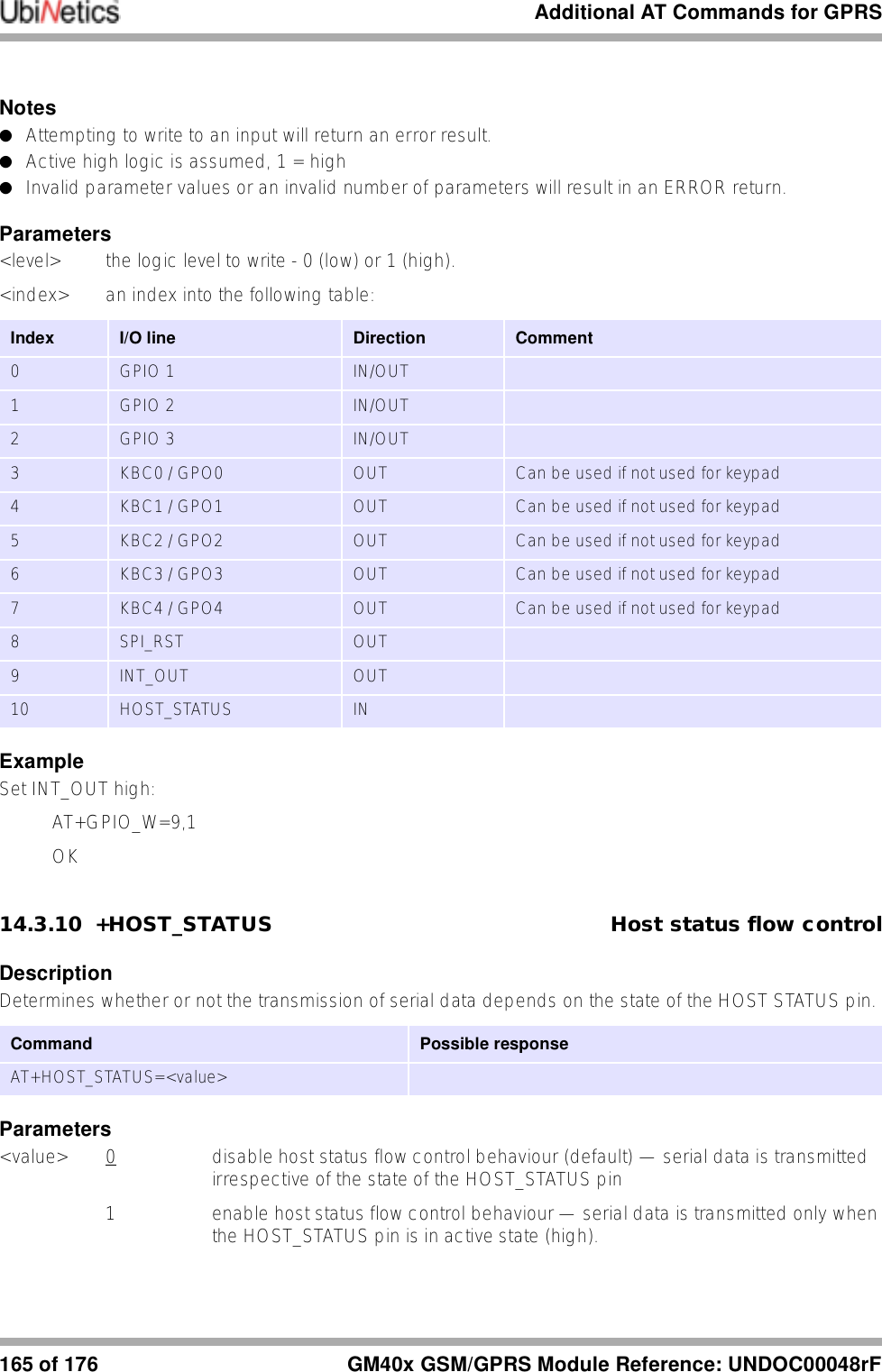
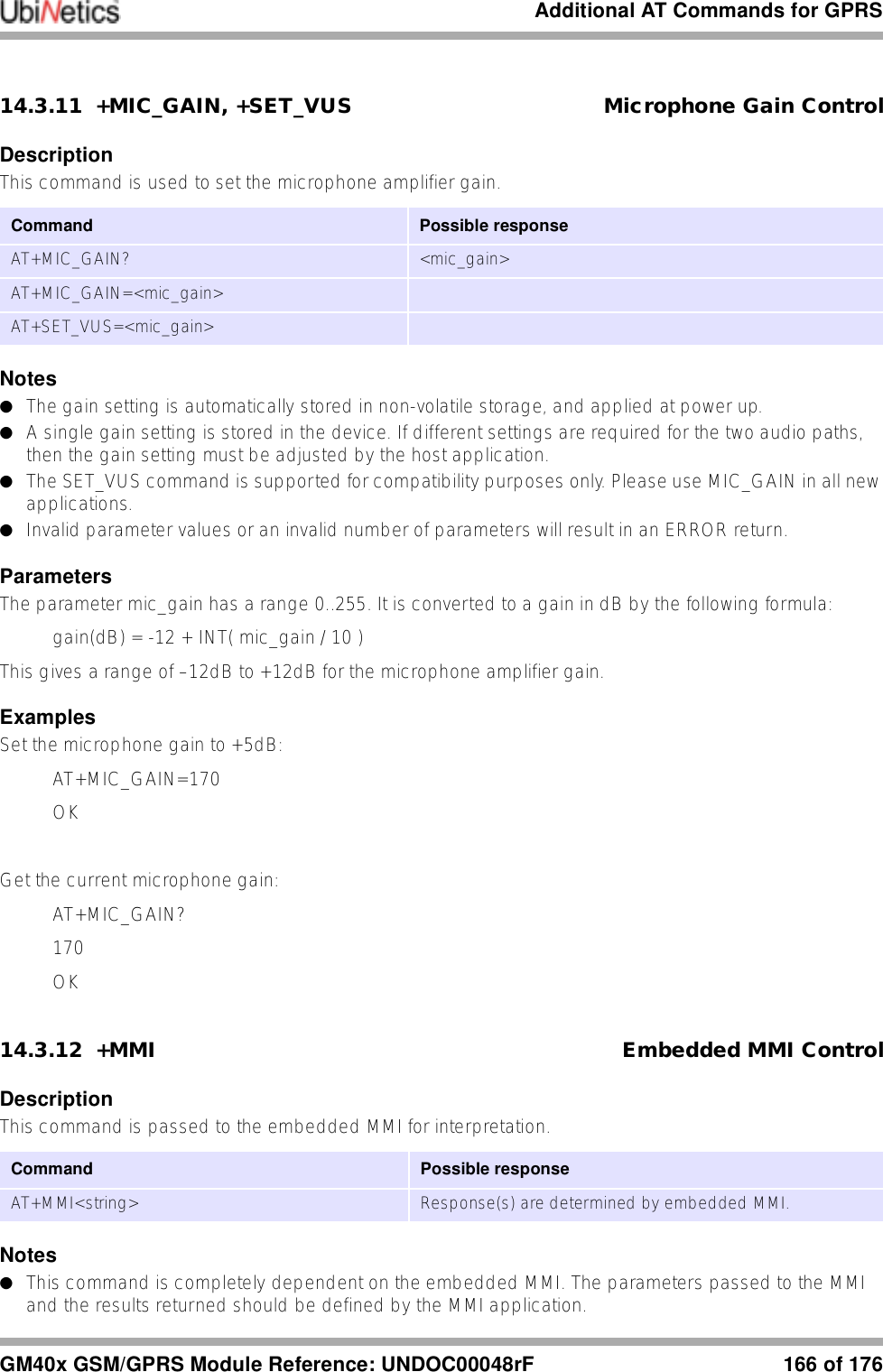
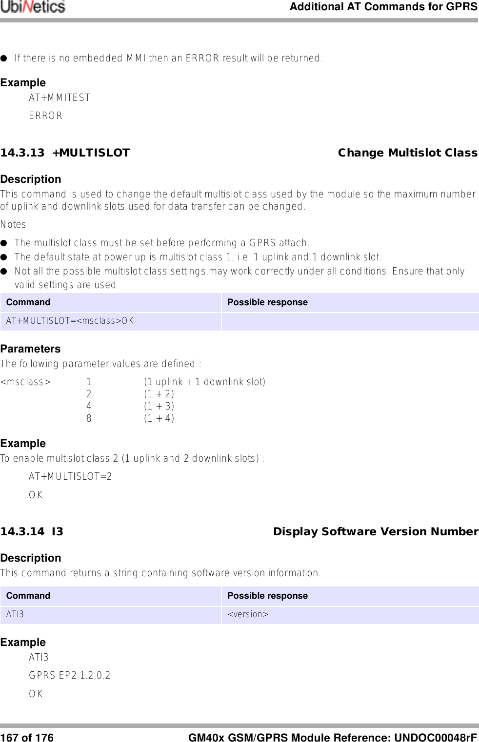
![Additional AT Commands for GPRSGM40x GSM/GPRS Module Reference: UNDOC00048rF 168 of 17614.3.15 +POWER_DOWN Power Down ModuleDescriptionThis command switches off the module power. No more commands will be processed—power up has to be carried out in hardware. ExampleAT+POWER_DOWN14.3.16 +RESET ResetDescriptionThis command is used to reset the module.Notes●There is no response produced as the module is reset immediately.ExamplesAT+RESET14.3.17 +RTC Real Time Clock ControlDescriptionThis command sets or gets the time from the real-time clock..Notes●Time is set and reported in 24-hour format only. ●Date parameters are optional in the set command, and if omitted just the time is set. The year is stored internally as 2 digits only but should be entered as a four digit value, e.g. 2001. ●The individual time and date fields are validated for range, and date validity checking is performed.●The RTC supports automatic leap year management.●Invalid parameter values or an invalid number of parameters will result in an ERROR return.ParametersPossible 'set' parameter values are as follows:Command Possible responseAT+POWER_DOWNCommand Possible responseAT+RESET NoneCommand Possible responseAT+RTC? +RTC:<date / time string>AT+RTC=<hour>,<minute>,<second>[,<day>,<month>,<year>]](https://usermanual.wiki/Ubinetics/GM401.User-manual/User-Guide-233185-Page-173.png)