VIERLING Communications ECVTM-PRO Cellular Gateway System User Manual Manual ECOTEL VTMpro 1 1
VIERLING Communications GmbH Cellular Gateway System Manual ECOTEL VTMpro 1 1
Contents
- 1. Users Manual Part I
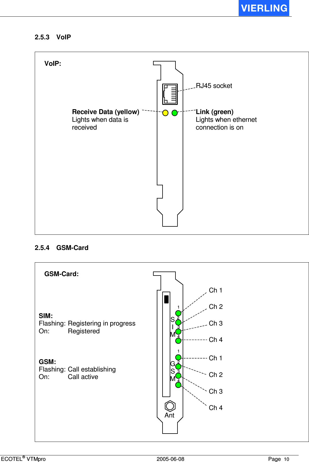
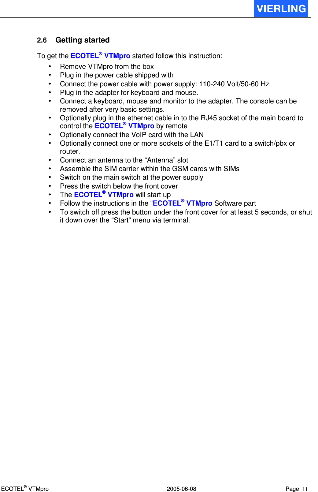
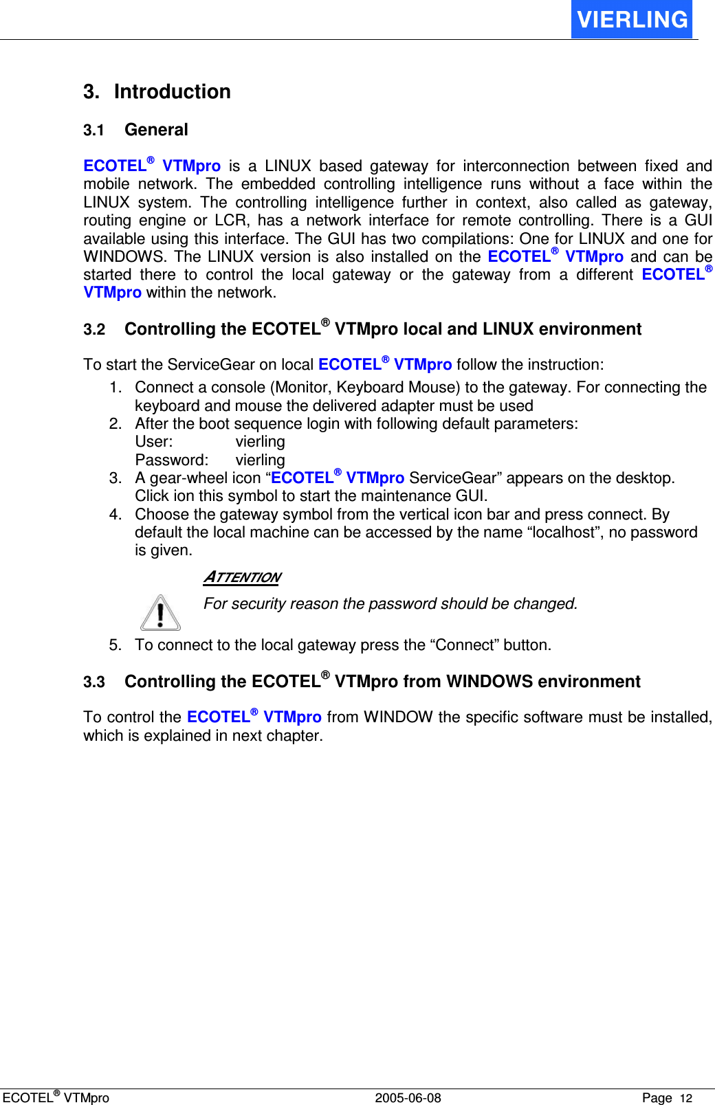
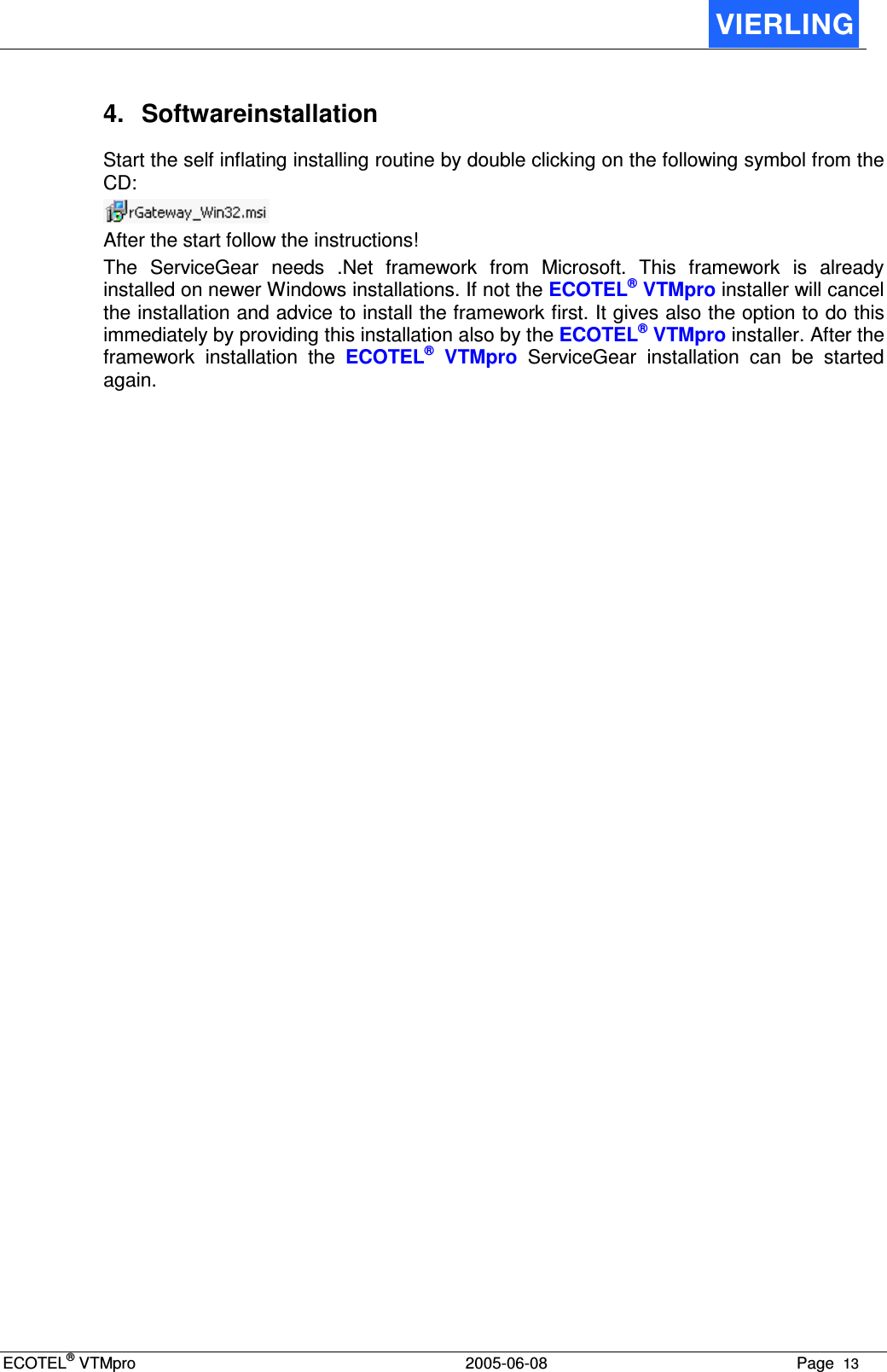
- 2. Users Manual Part II
- 3. Users Manual Part III
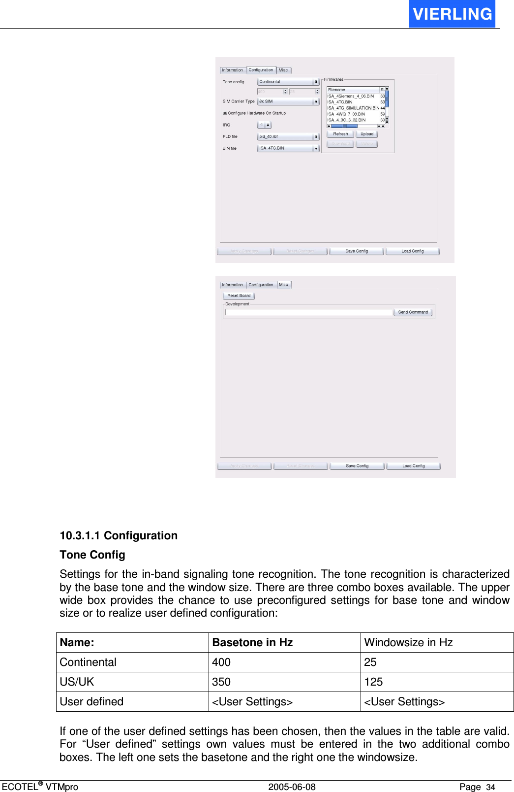
Users Manual Part II