Viconics Electronics VWAP Wireless door and window switch User Manual
Viconics Electronics Inc. Wireless door and window switch Users Manual
UserManual.wiki
>
Viconics Electronics
>
VWAP User Manual
Users Manual
Navigation menu
Upload a User Manual
Namespaces
Wiki Guide
HTML
PDF
Info
Views
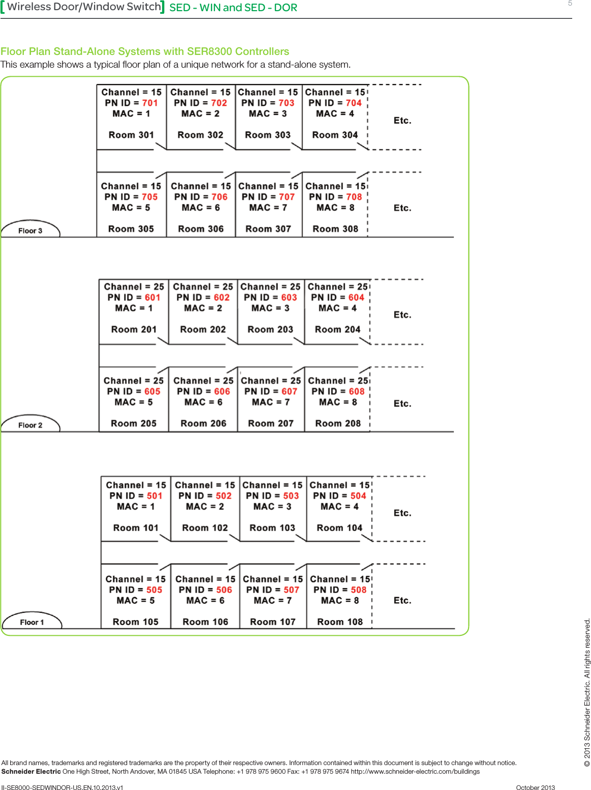
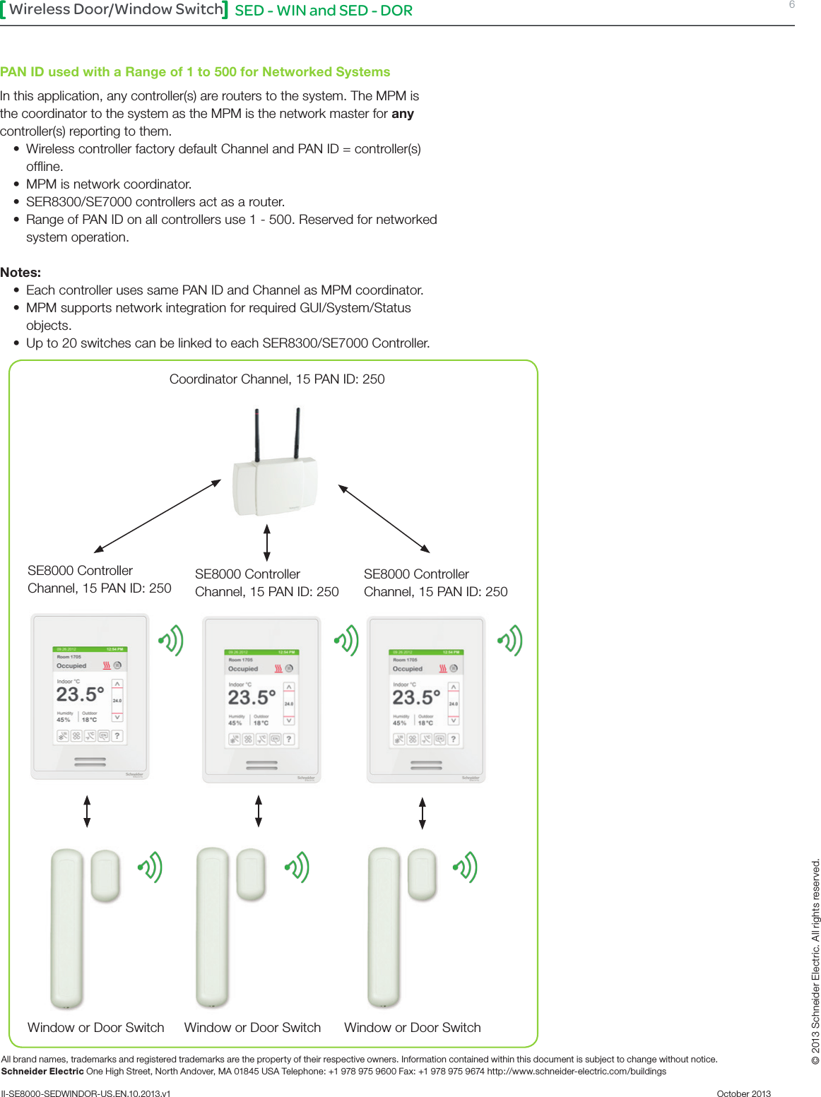
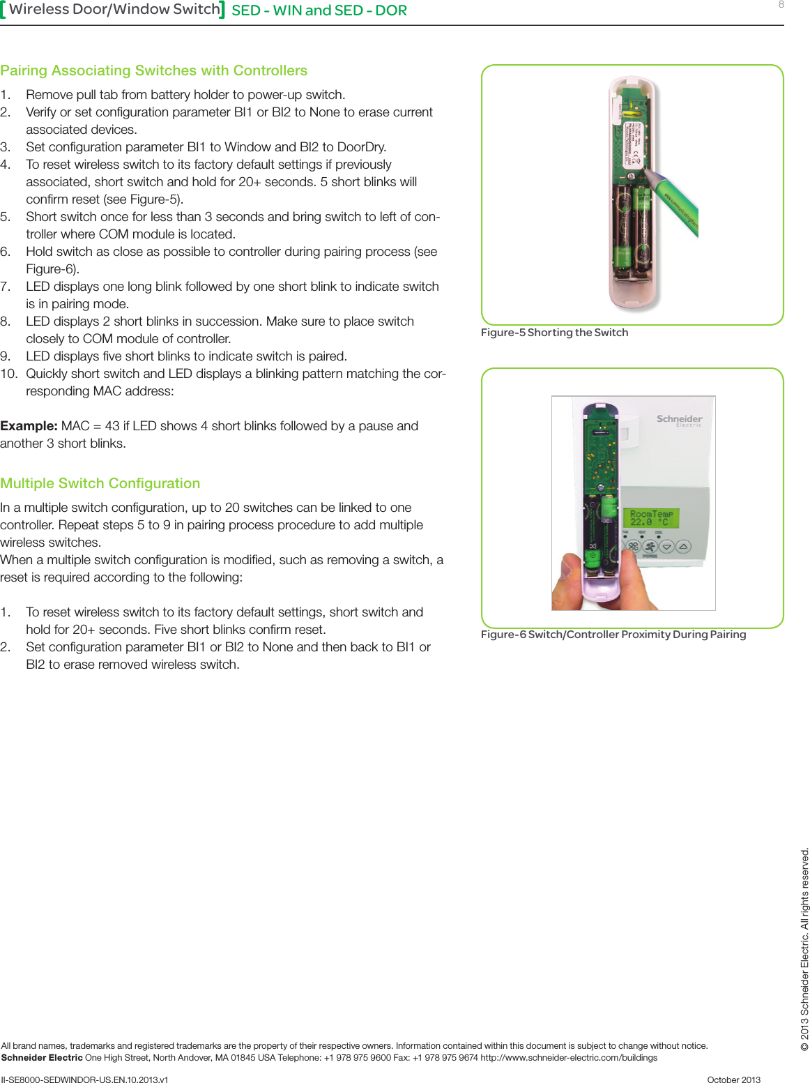
User Manual
Discussion / Help
Navigation