ViewSonic VS15989 Wireless Presentation Dongle User Manual 319 v1 1
ViewSonic Corporation Wireless Presentation Dongle User Manual 319 v1 1
UserManual.wiki
>
ViewSonic
>
VS15989 User Manual
Users Manual
Navigation menu
Upload a User Manual
Namespaces
Wiki Guide
HTML
PDF
Info
Views
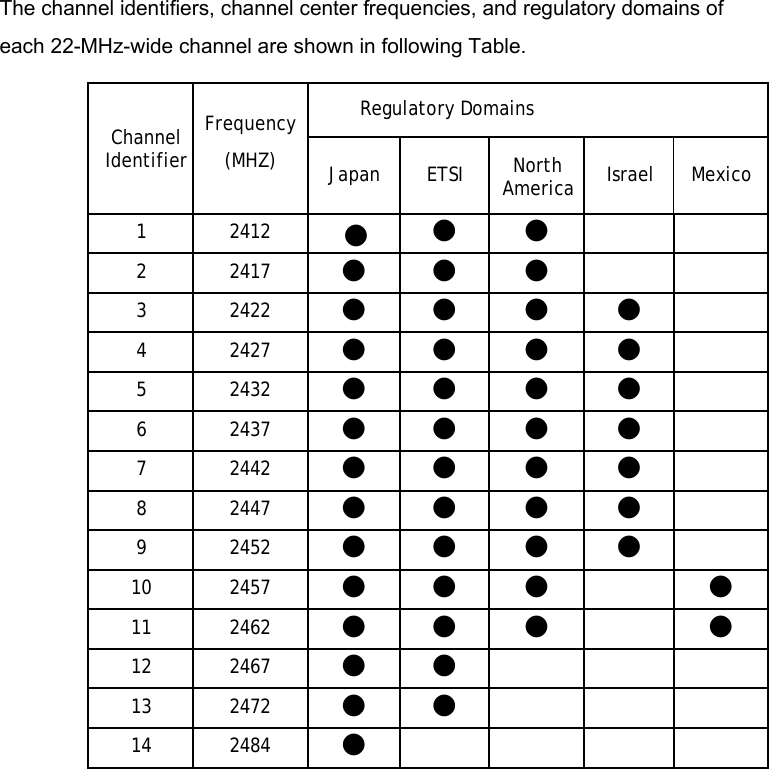
User Manual
Discussion / Help
Navigation