Vivosonic V50 VIVOLINK User Manual USER S MANUAL
Vivosonic, Inc. VIVOLINK USER S MANUAL
UserManual.wiki
>
Vivosonic
>
V50 User Manual
>
USERS MANUAL 2
Contents
1.
USERS MANUAL 1
2.
USERS MANUAL 2
USERS MANUAL 2
Navigation menu
Upload a User Manual
Namespaces
Wiki Guide
HTML
PDF
Info
Views
User Manual
Discussion / Help
Navigation
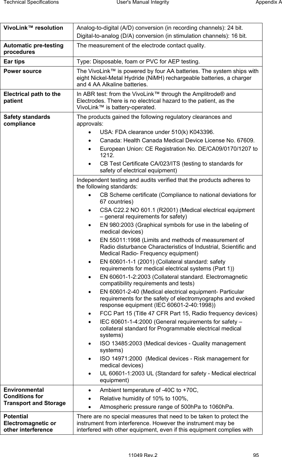
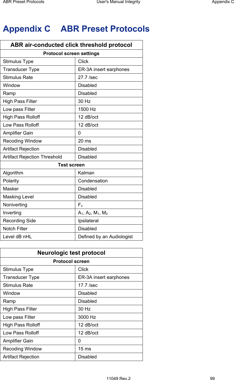
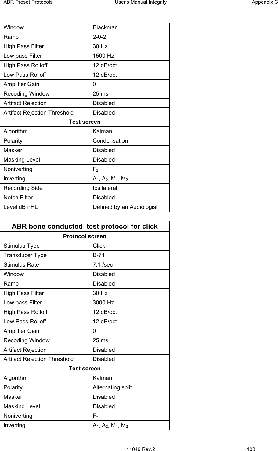
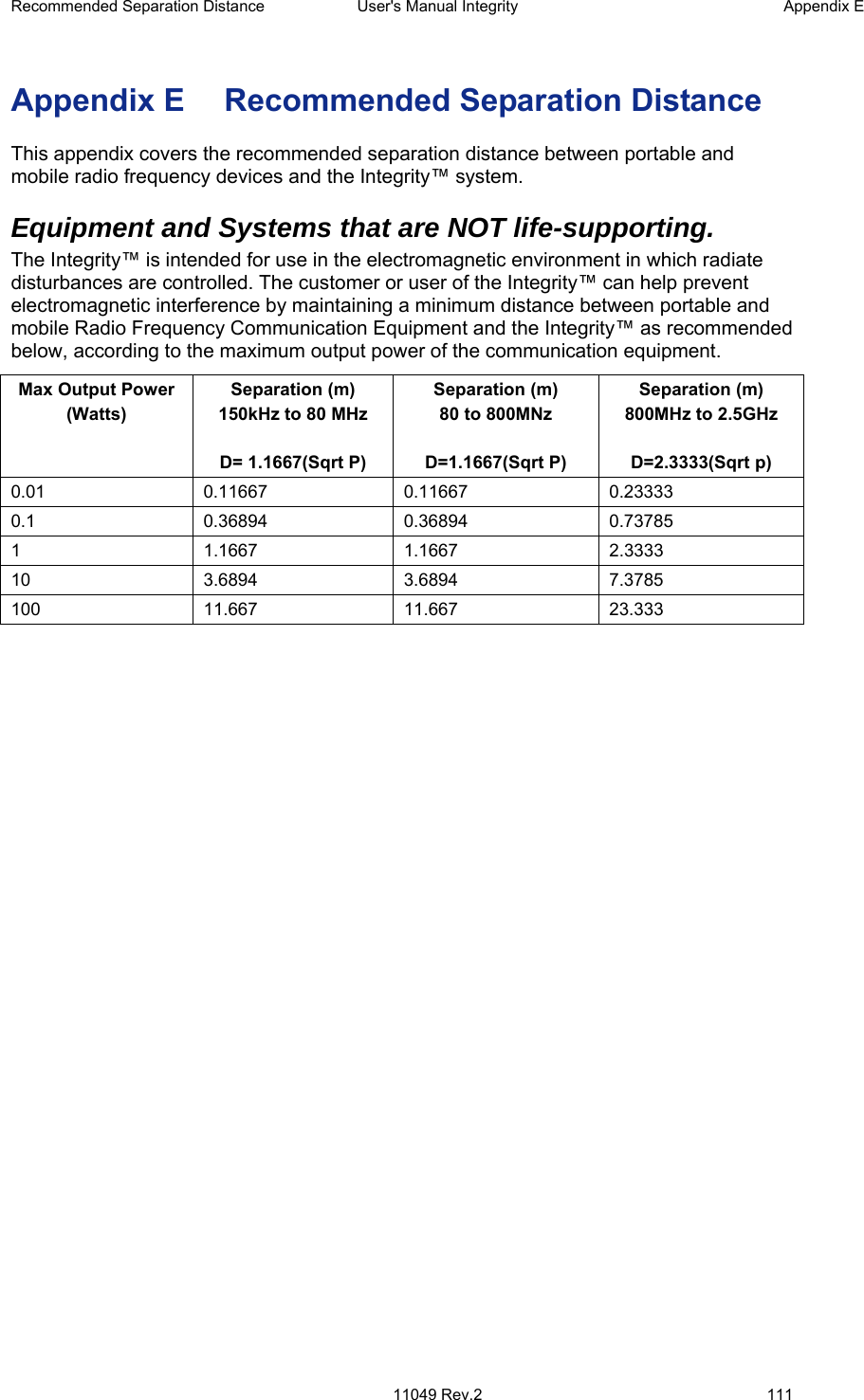
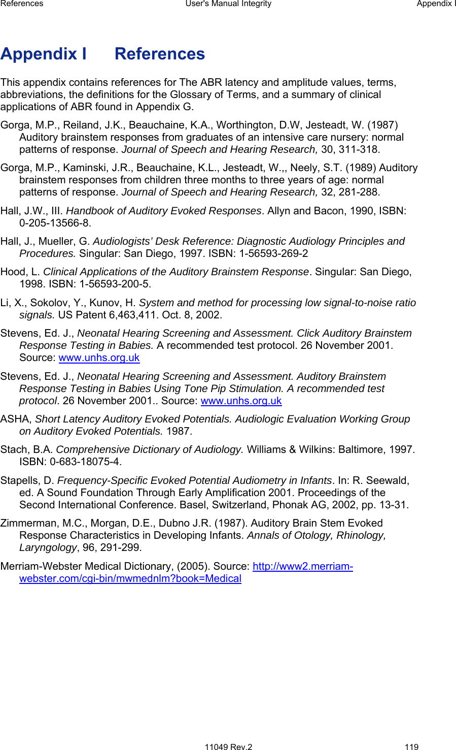
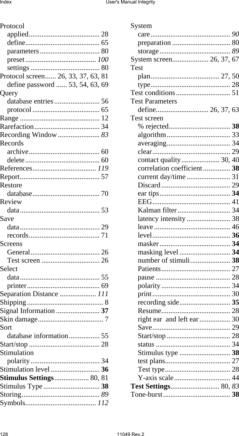
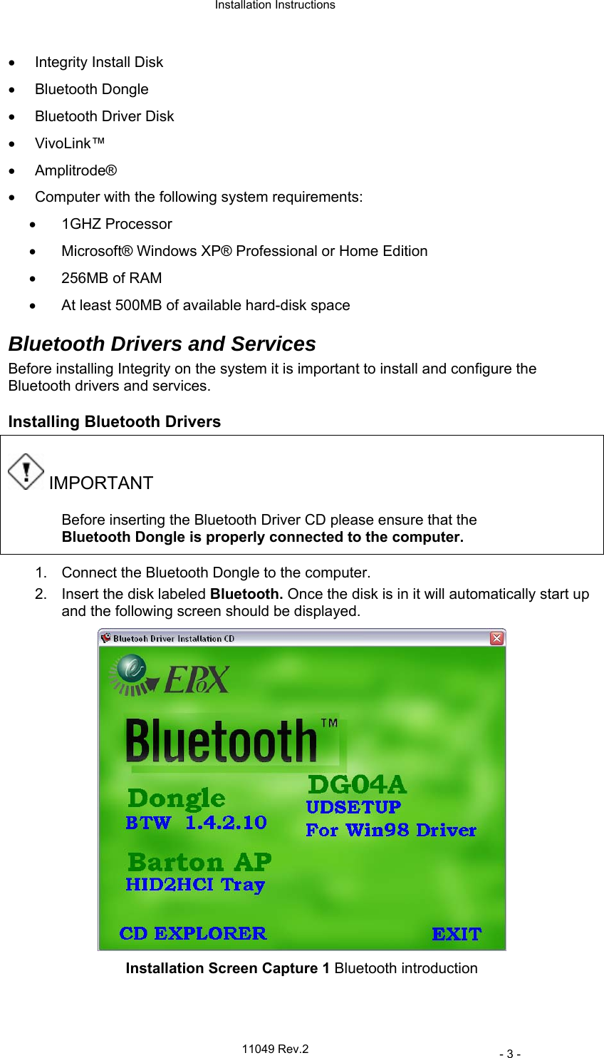
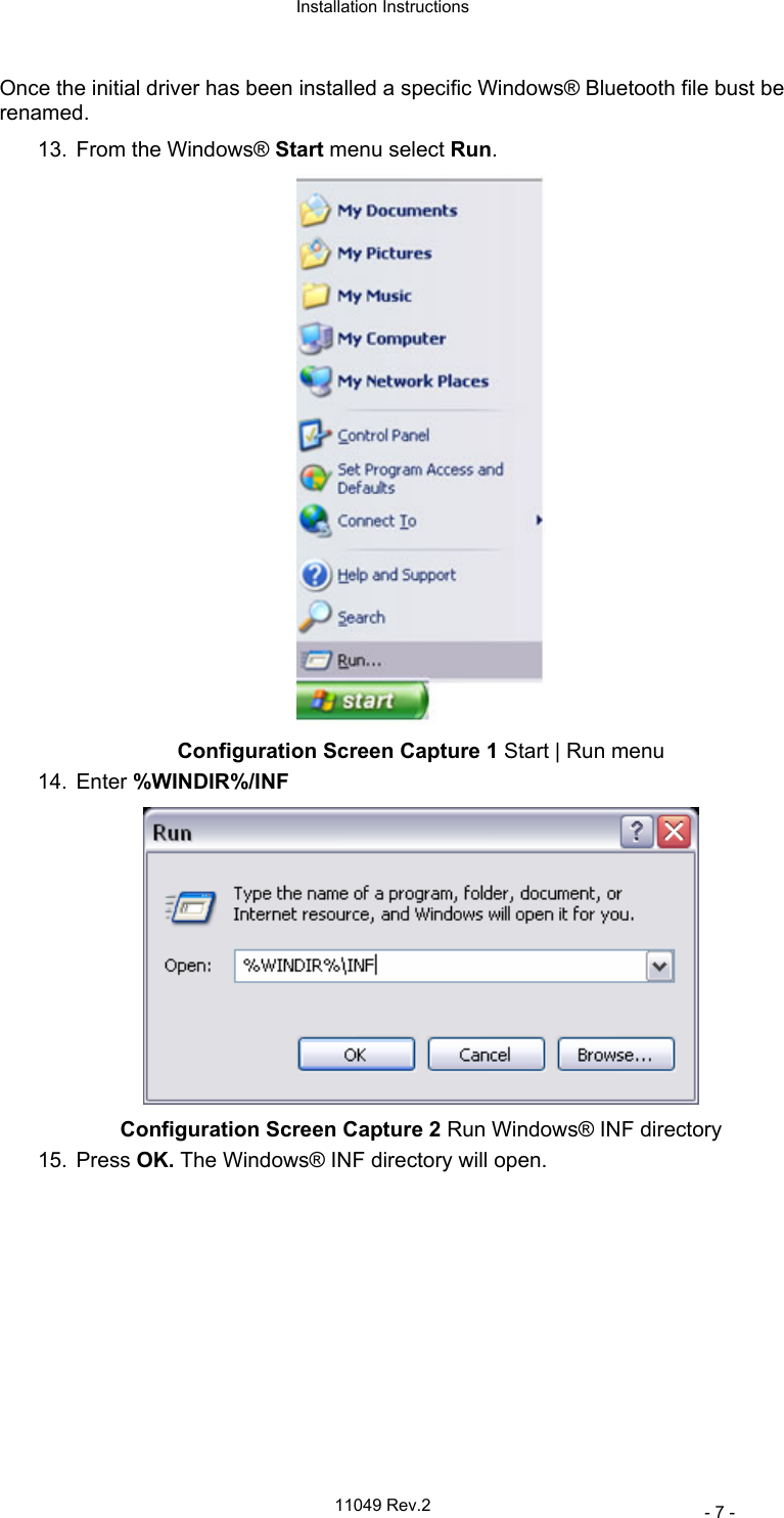
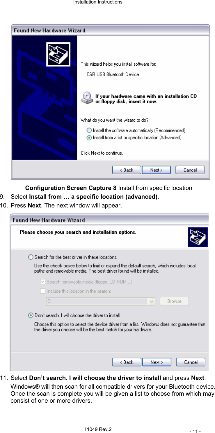
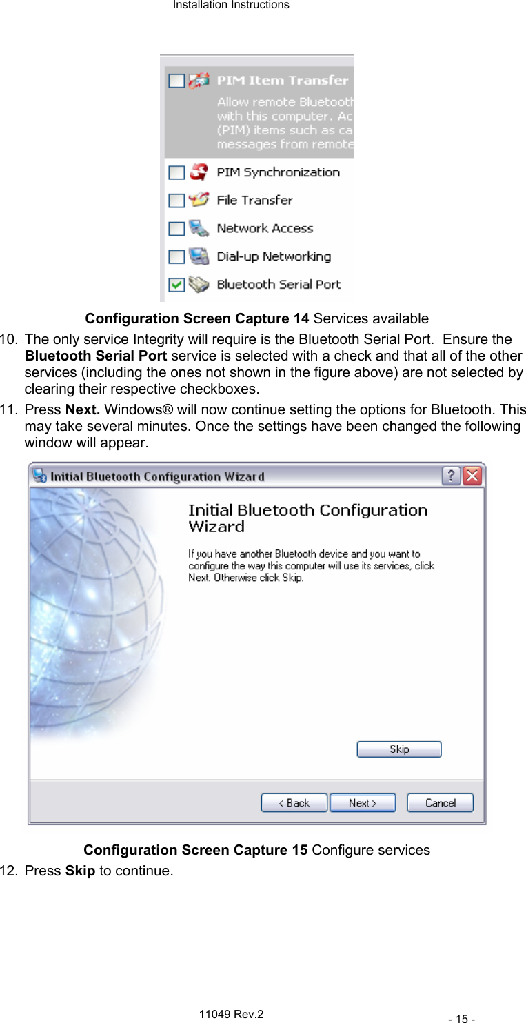
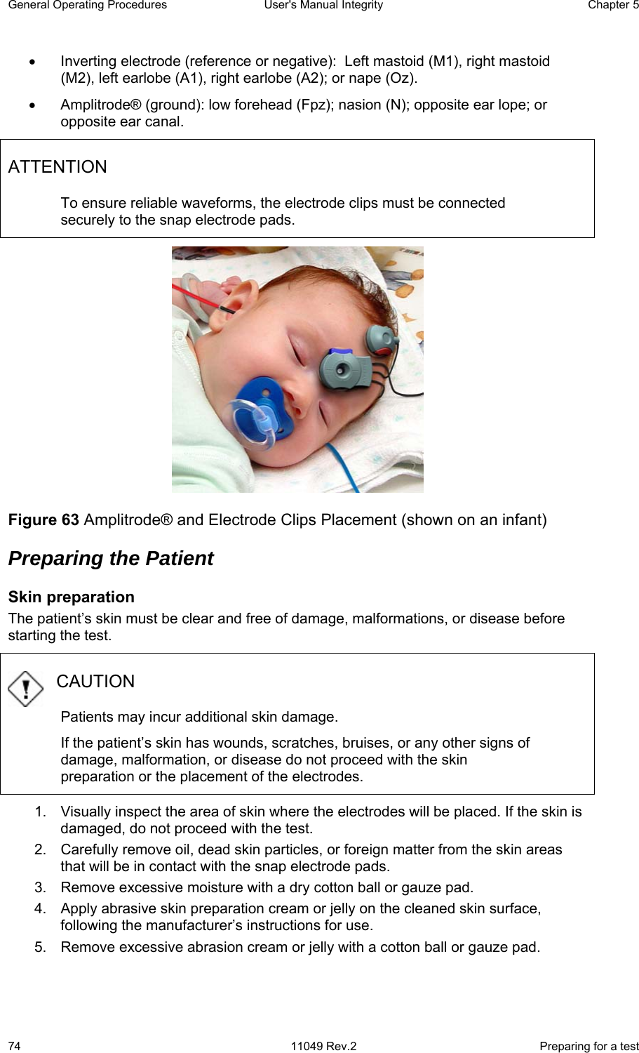
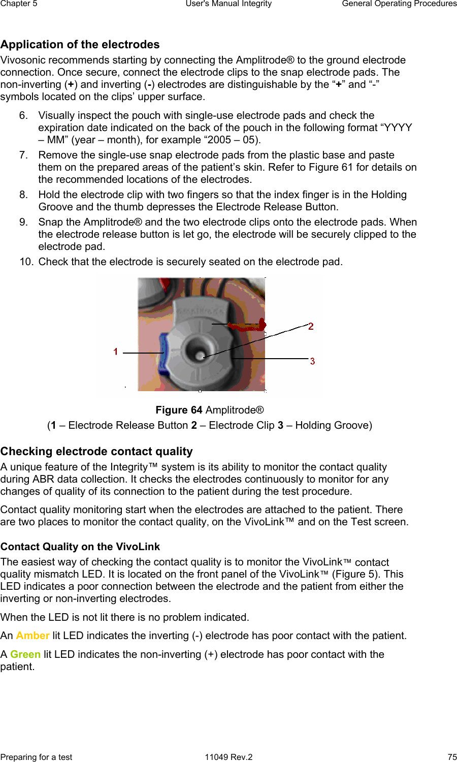
![Chapter 5 User's Manual Integrity General Operating Procedures Preparing for a test 11049 Rev.2 73 Recommended electrode placement NOTE The patient’s skin must be prepared before the snap electrode pads can be attached. The following electrode placement configurations are recommended for the Amplitrode®, which is optimized for a single-channel recording (Figure 61). [Hall, 1990], [Hall, 1997], [Stapells, 2001] Figure 61 Typical electrode placement diagram - front view Figure 62 Typical electrode placement diagram - left lateral view The recommended electrode sites are: • Non-inverting electrode (active or positive): High forehead (Fz).](https://usermanual.wiki/Vivosonic/V50.USERS-MANUAL-2/User-Guide-624488-Page-1.png)
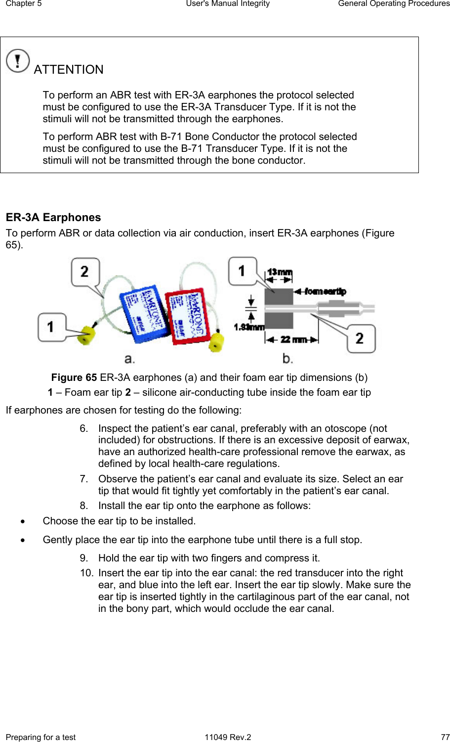
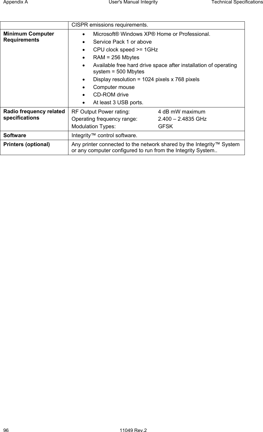
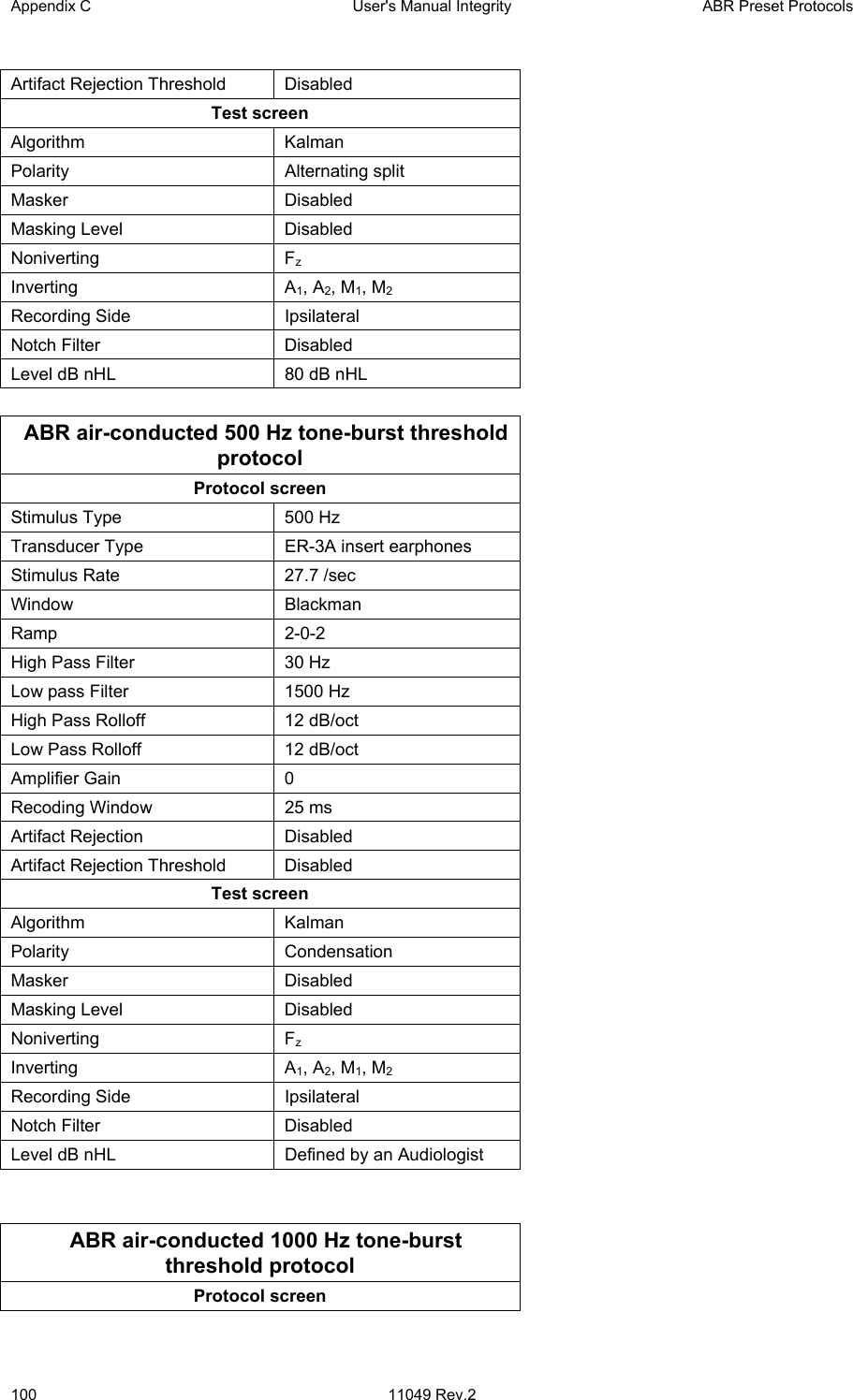
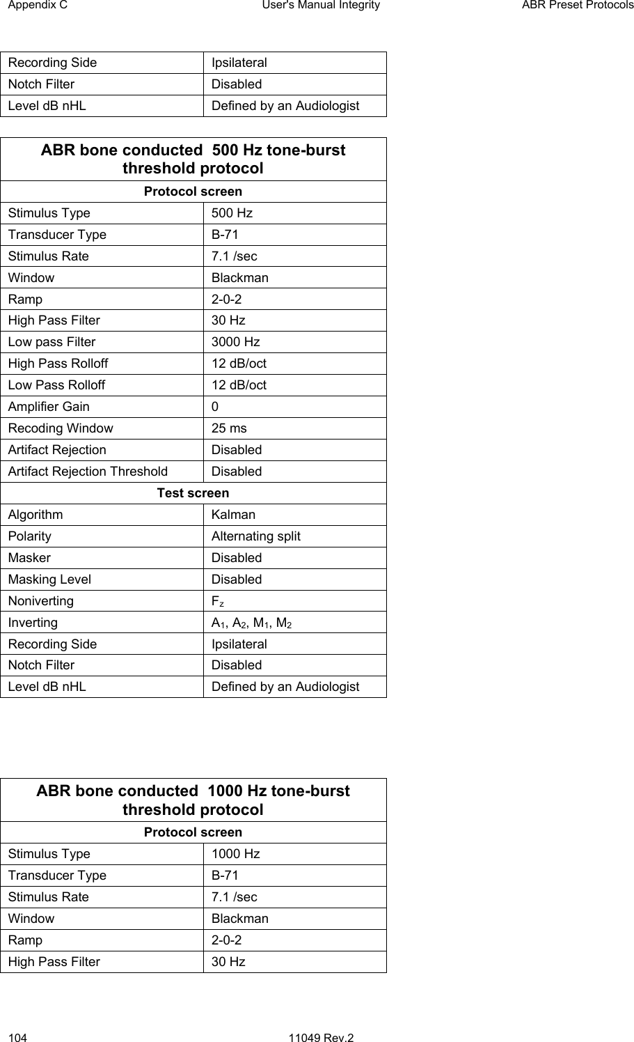
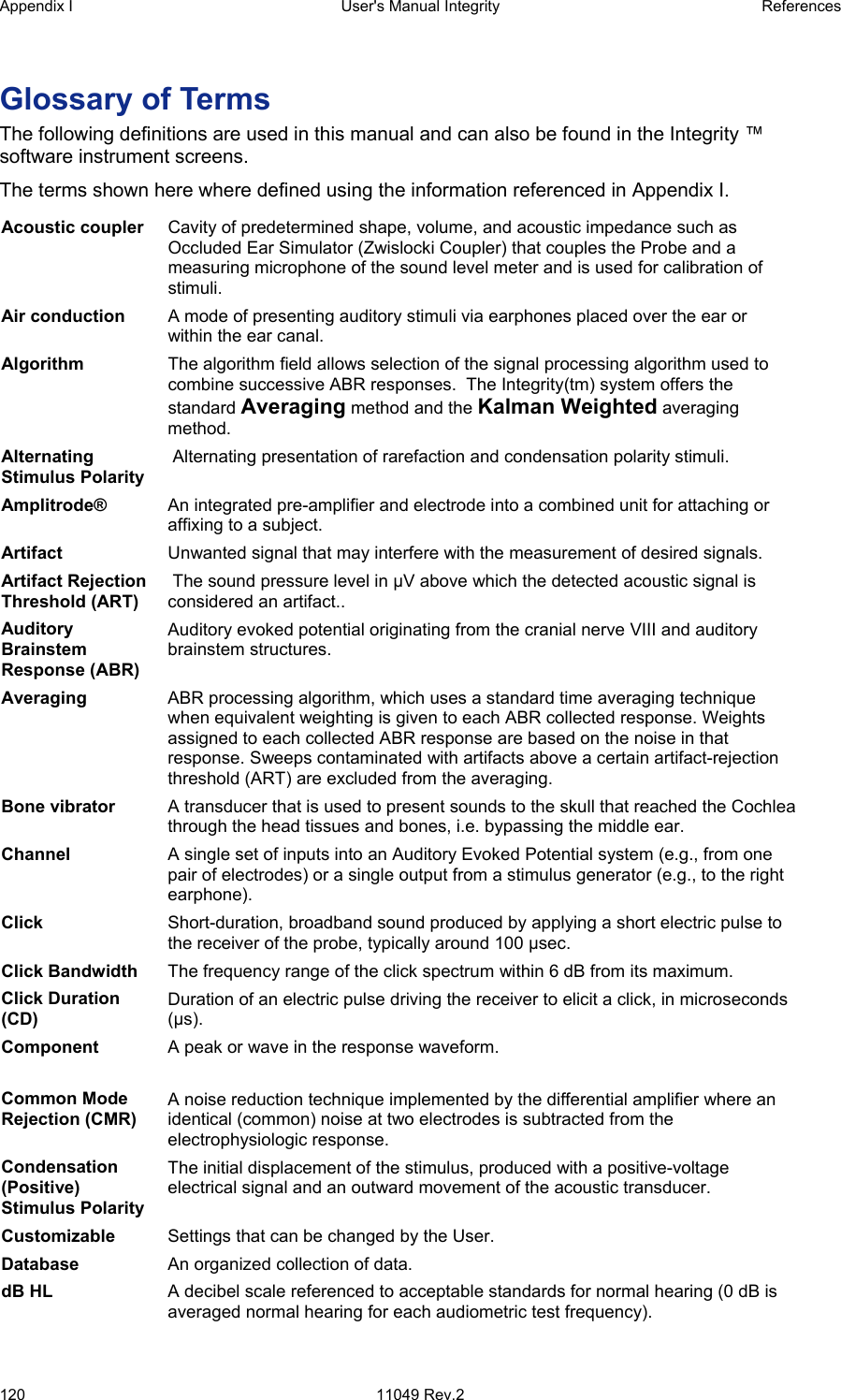
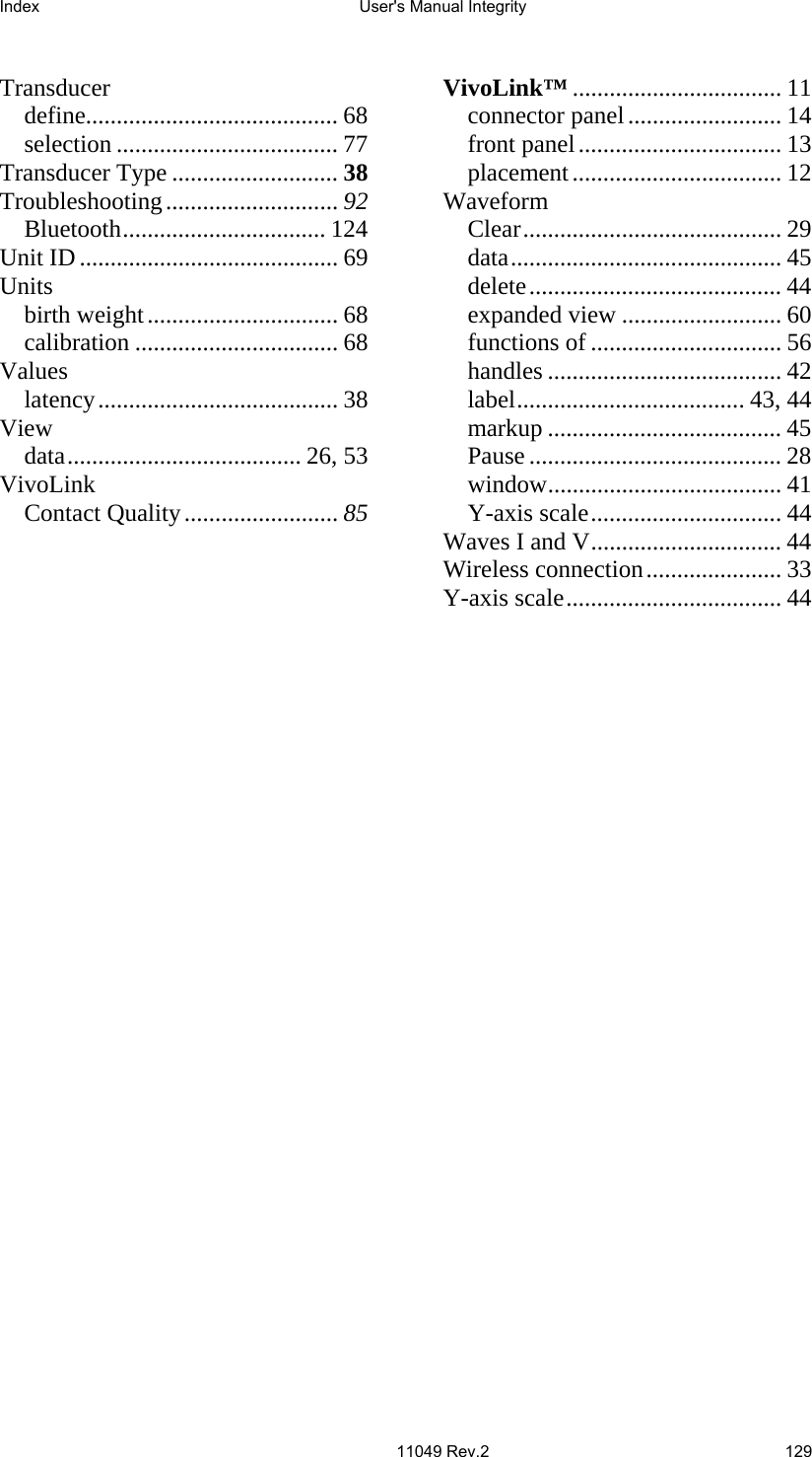
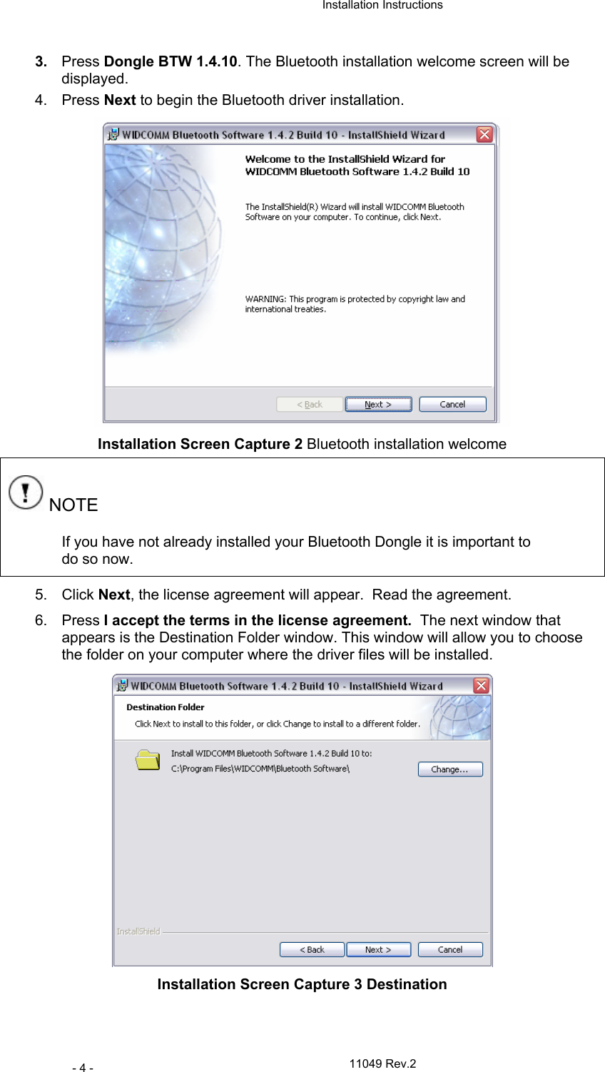
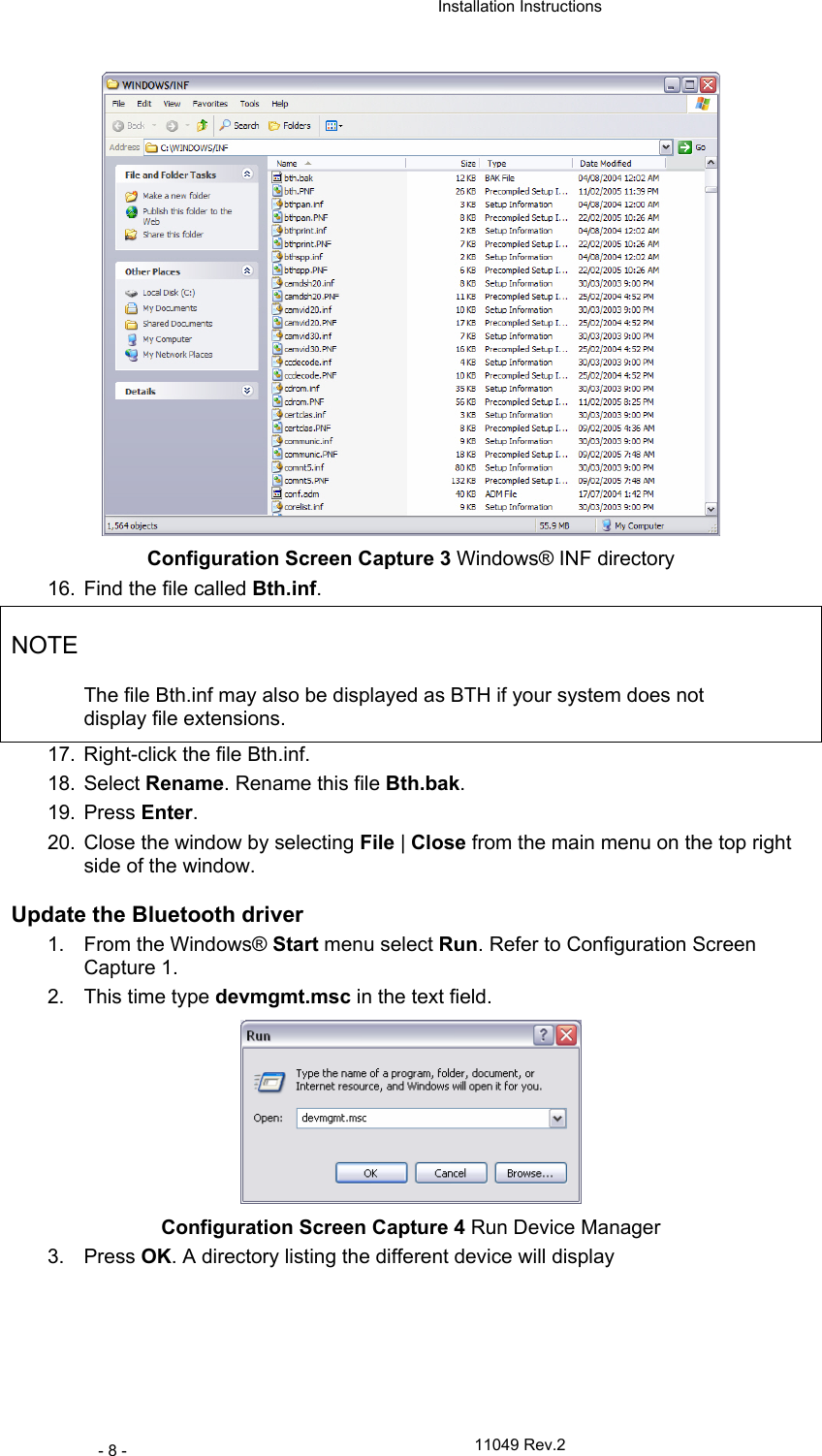
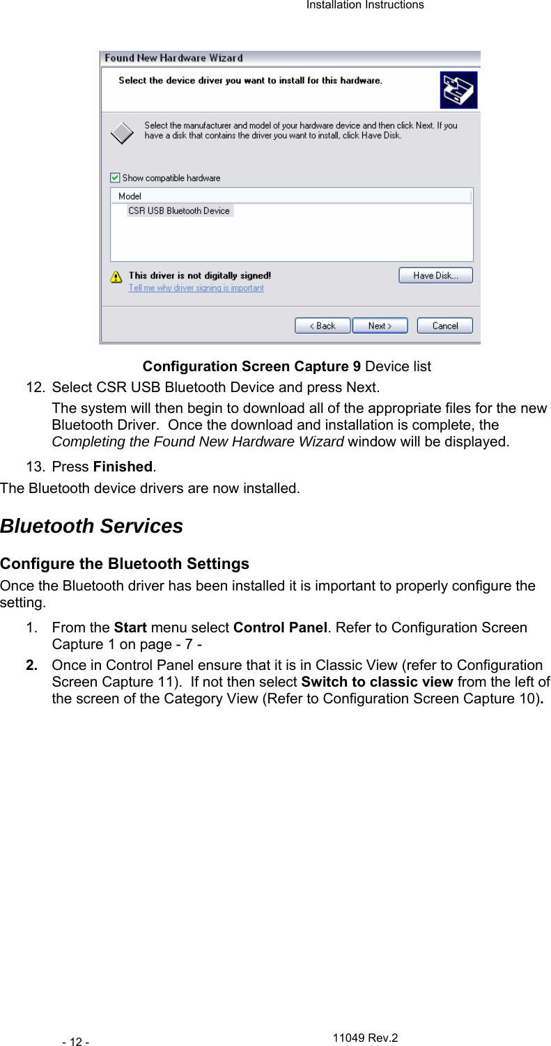
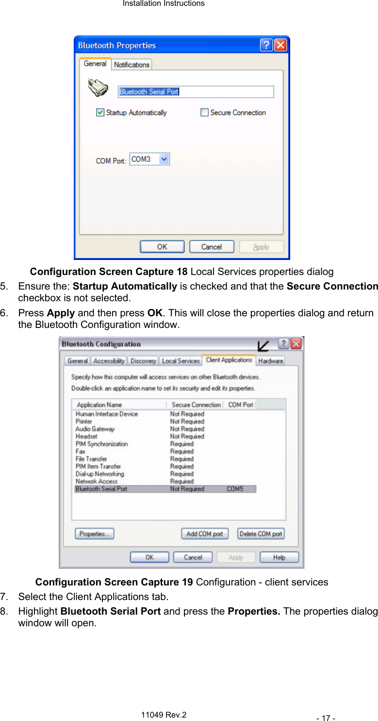
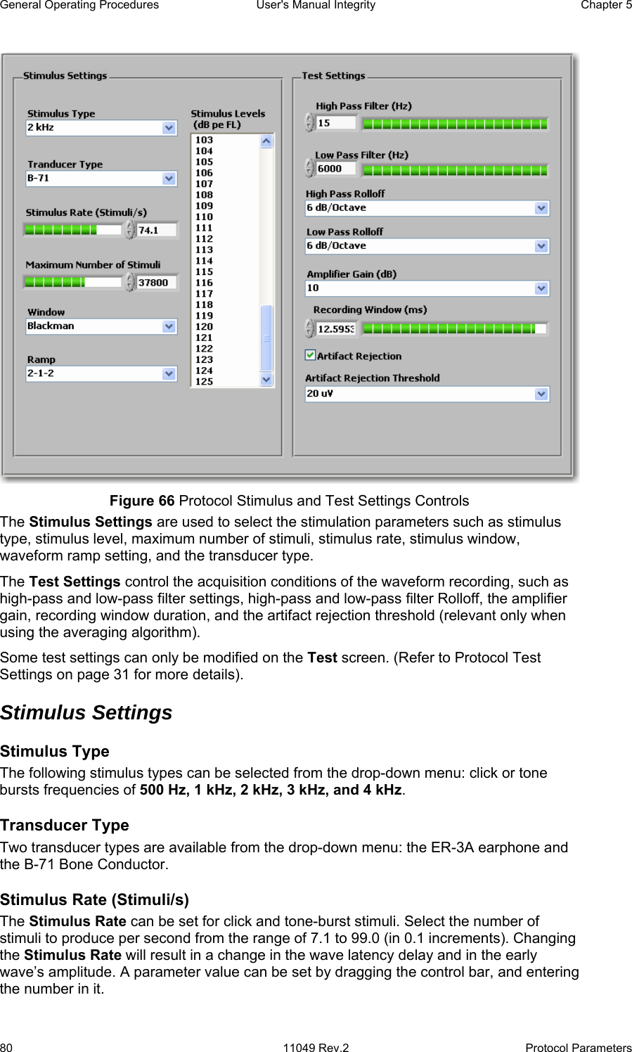
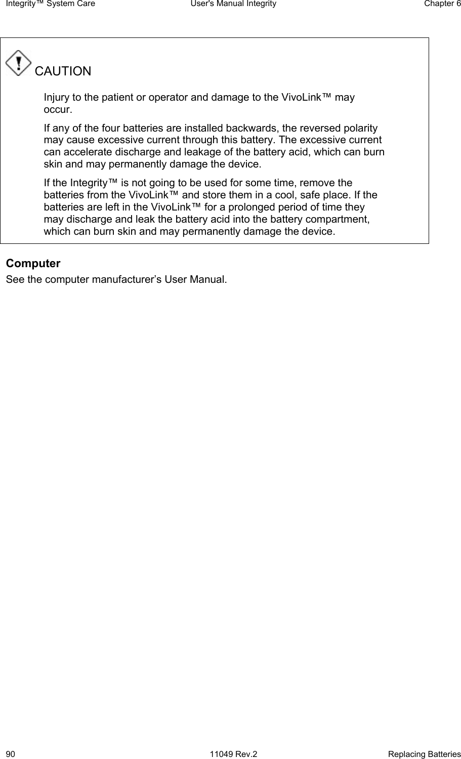
![Chapter 5 User's Manual Integrity General Operating Procedures Protocol Parameters 11049 Rev.2 79 Preparation of the system To prepare for a test, perform the following operations: 1. To ensure there is no visible mechanical damage, inspect the VivoLink™, Amplitrode®, Amplitrode® clips, Amplitrode® connectors, and Amplitrode® cable; ER-3A Insert Earphones and their connectors, cables, and silicone tubes; the B-71 Bone Conductor and its cable and connector. 2. Visually inspect the Amplitrode® and its clips to ensure they are clean of any debris. 3. Place the Amplitrode® and its clips on the parking snaps located on the front panel of the VivoLink™ (Figure 5). CAUTION Do not conduct any AEP test if by visual inspection you discover any visible mechanical damage. Report the problem to Vivosonic’s local service representative or Vivosonic Customer Support. Do not try to repair the device yourself. Do not conduct any AEP test if the Amplitrode® or its clips are congested with any debris which may cause improper electrical contact with the electrode-pad snaps and improper testing. 4. Switch on the computer. 5. Read the two Caution statements (Figure 10 and Figure 11), and choose Agree. Pressing Agree will open the software to the Patients screen (Figure 35). Pressing EXIT will shut down the computer. 6. To be able to perform tests select at least one patient’s name from the list of existing patient or add a new patient name and select it for testing. 7. Switch On the VivoLink™ and monitor the power indicator (Figure 4). The power indicator which is located on the front panel (Figure 5) will turn on green if the batteries in the VivoLink™ are in good working condition. If the battery power is low the indicator will turn amber. Replace the batteries before starting. 8. Check the Bluetooth® connection of the VivoLink™ with the system computer. If connection has been established the VivoLink™ Bluetooth® indicator light ( Figure 20) turns blue. When the connection has been lost the Bluetooth® LED indicator will appear not lit. Protocol Parameters The protocol parameters are entered using ABR Stimulus and Test Settings controls [Hall, 1990], [Hall, 1997], [Stapells, 2002], [Stevens, 2001, (Click)], [Stevens, 2001 (Tone Pip)]. To create a new protocol select an existing protocol and modify it. The parameters, which can be preset in this protocol, are divided into two categories: Stimulus Settings and Test Settings (Figure 53).](https://usermanual.wiki/Vivosonic/V50.USERS-MANUAL-2/User-Guide-624488-Page-7.png)
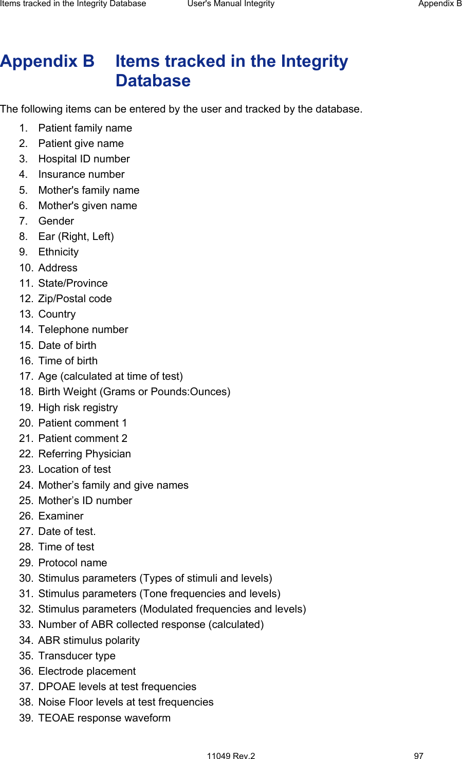
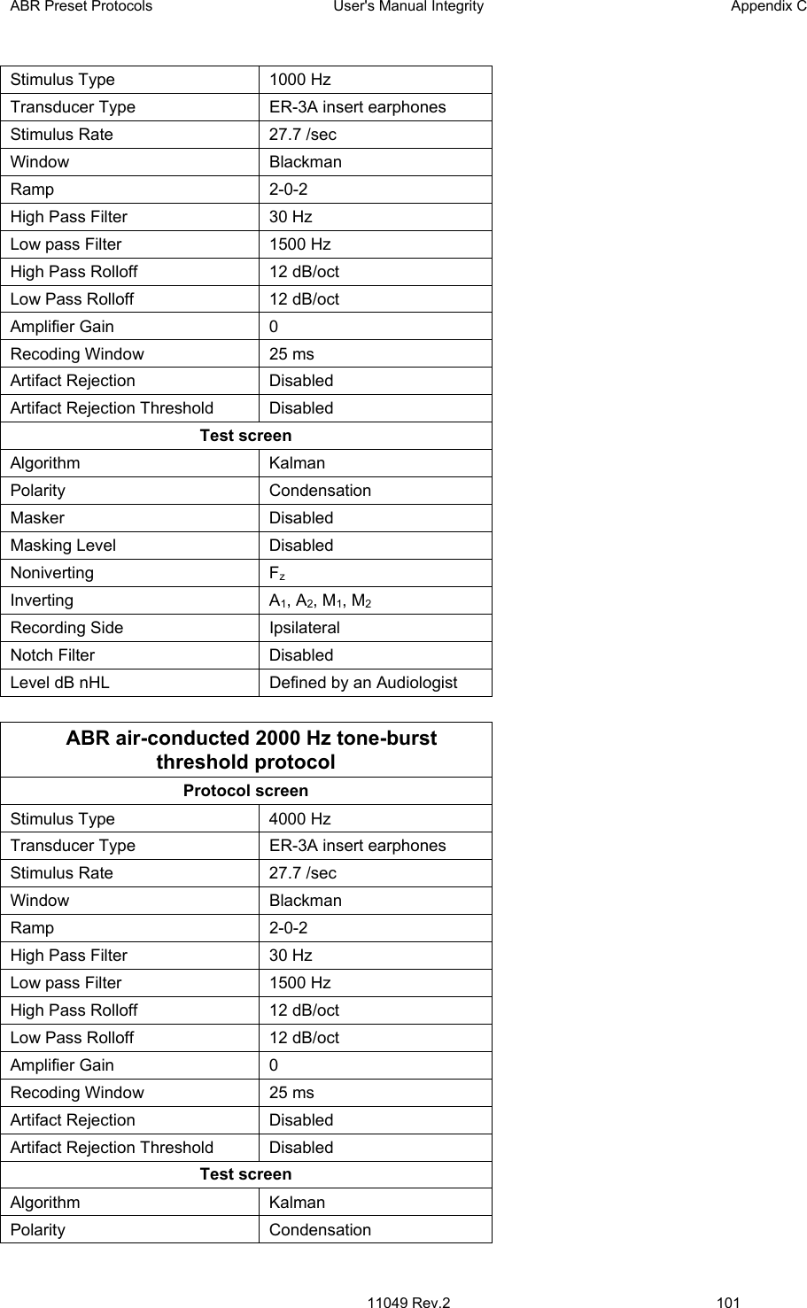
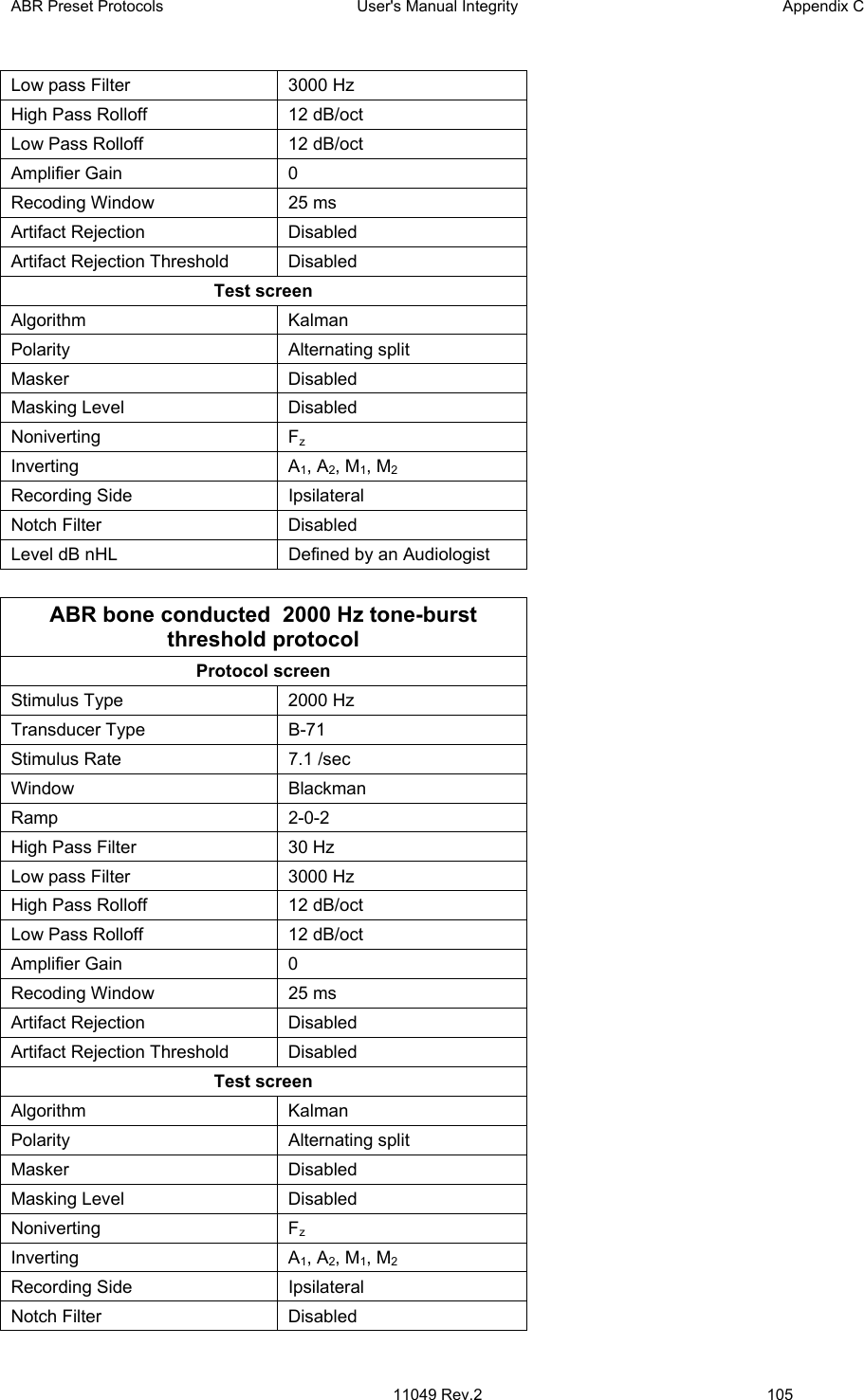
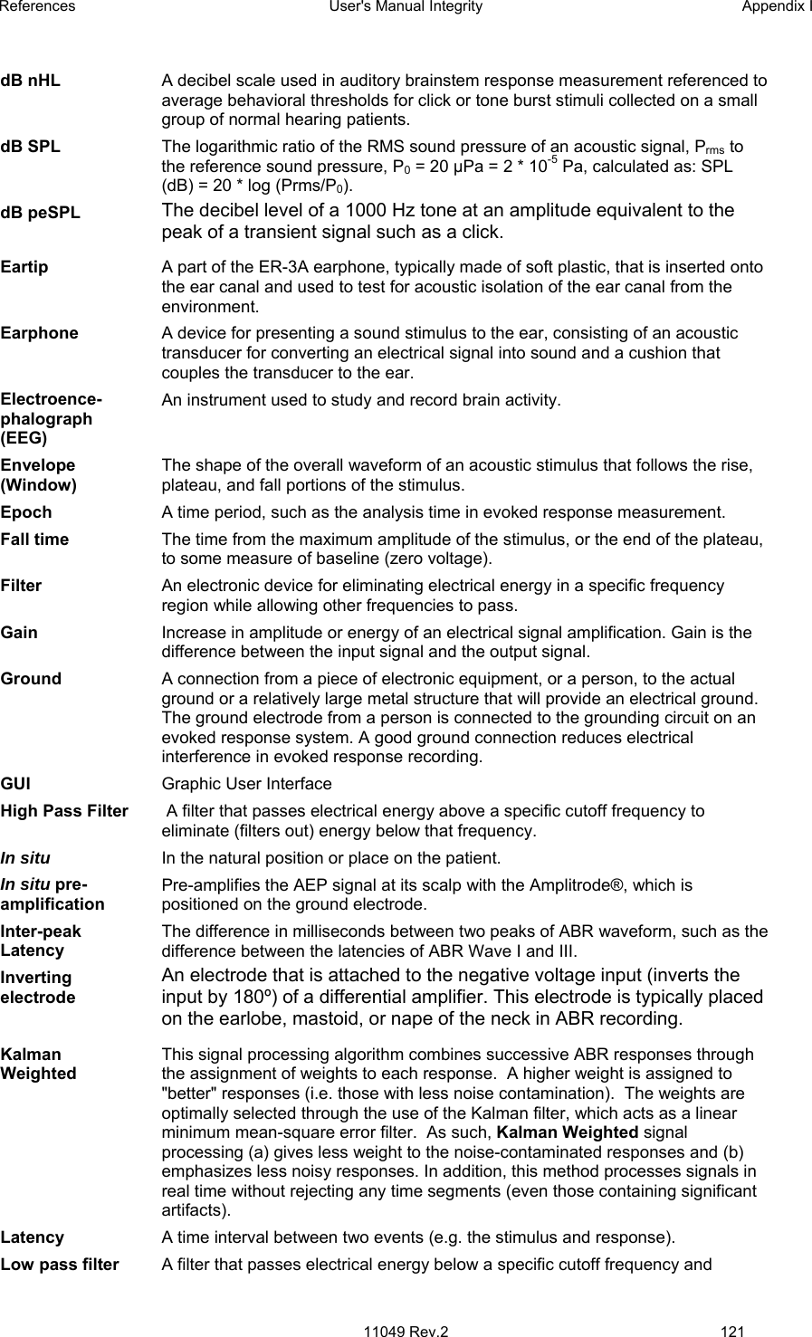
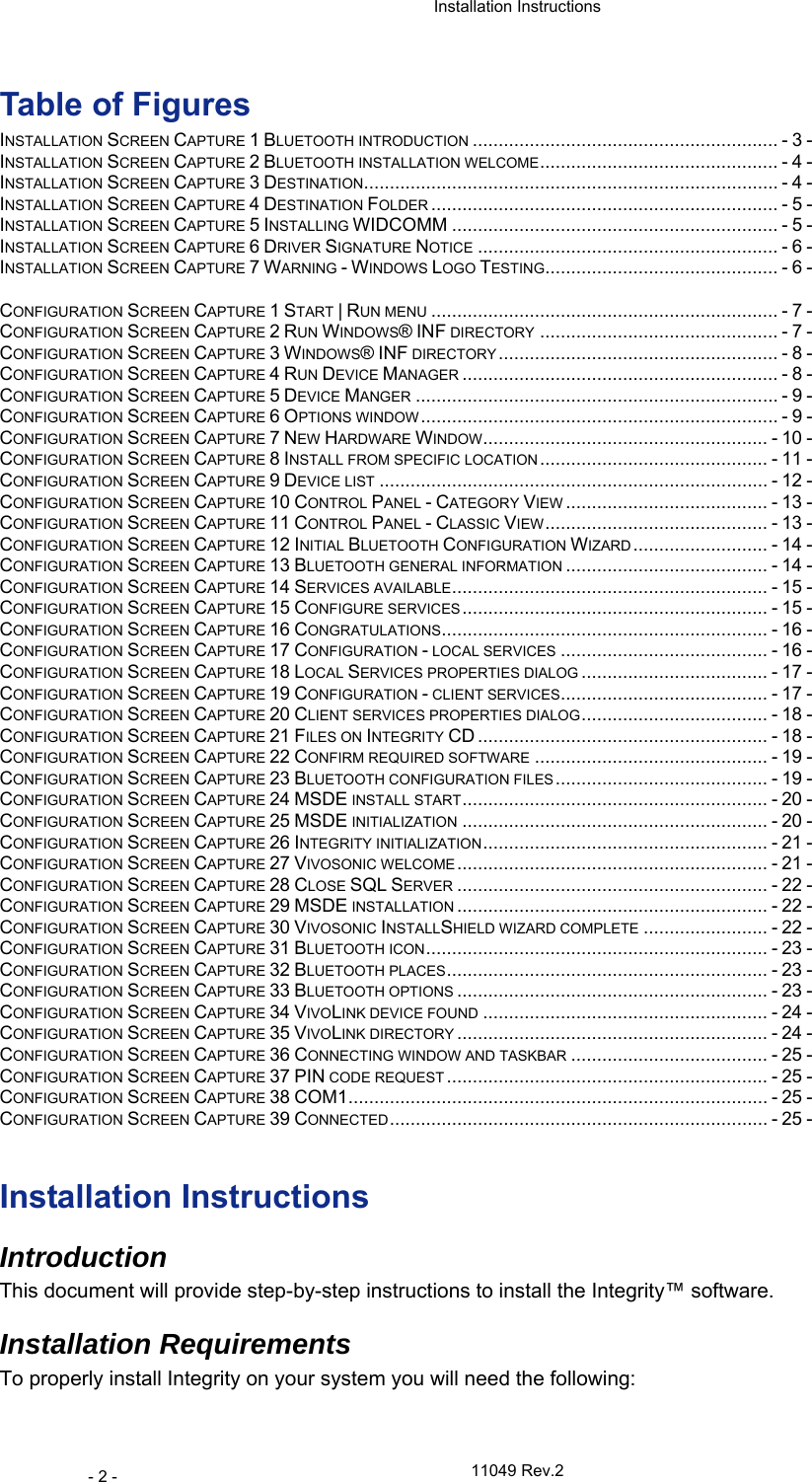
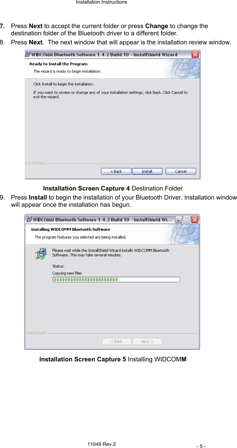
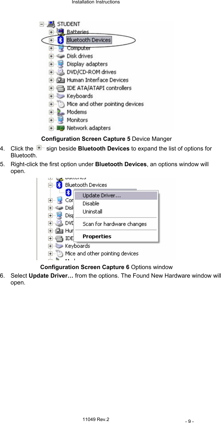
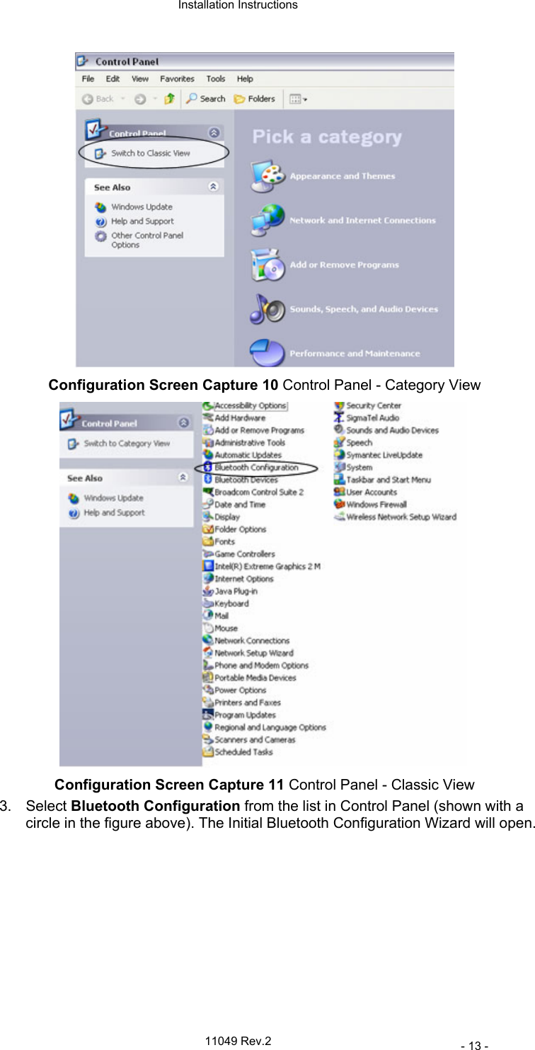
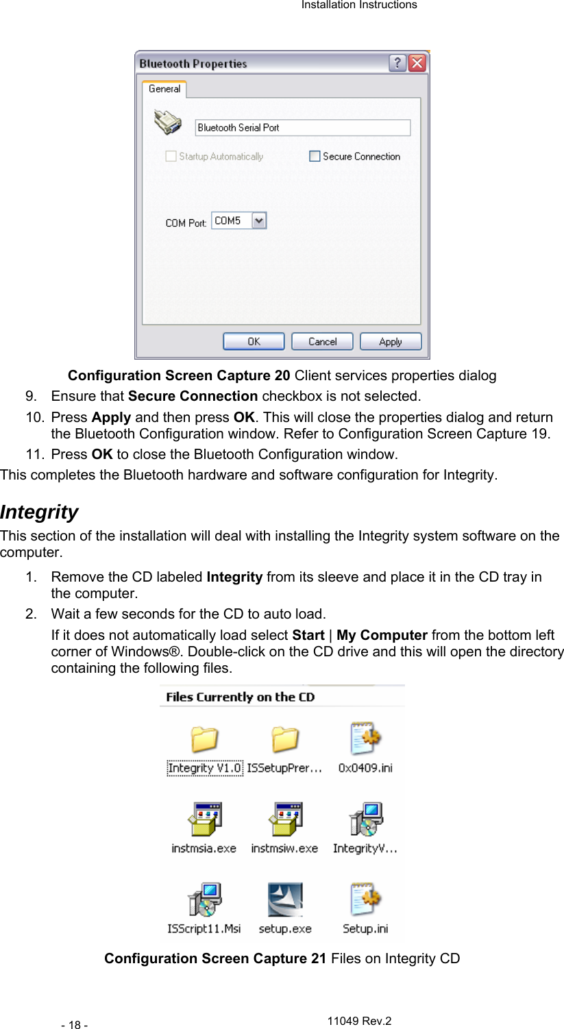
![Appendix A User's Manual Integrity Technical Specifications 94 11049 Rev.2 Chapter 8 Appendices Appendix A Technical Specifications Intended use Hearing screening and clinical assessment in newborns, infants, children, and adults. Digital Signal Processing (DSP) method The Kalman Weighted method, a patented method using a Linear Minimum Mean-Square Error Filter, also called the Kalman Filter (US Patents 6,463,411 and 6,778,955), is used to estimate ABR signals recording and a time-averaging method. [Li 2002] Test procedure Non-invasive. Patient participation/response Not required – ABR is objective. Diagnostic environment VivoLink™ will perform in a variety of environments (hospital, ambulatory, or home). A sound-proof room is typically not required. Compliant Transducers and cables Compliant with the requirements of EN60601-1-2:2001 Sections 36.201, 36.202 − ER-3A earphones attached to 55.5 ± 2.5 cm cable − B-71 Bone Conductor attached to 72” cable − OAE probe attached to 80 cm cable Compliant Accessories Compliant with the requirements of EN60601-1-2:2001 Sections 36.201, 36.202 Amplitrode® cables length: − between VivoLink™ and ground clip – 1 Meter − between ground clip and “+” clip” – 25 cm − between ground clip and “-“ clip – 40 cm VivoLink™ - wireless interface module Electrode type Single-use Ambu® Neuroline 720-00-S snap electrodes or equivalent. Amplitrode® filters For ABR: 30 – 3000 Hz. Slope: 12 dB/octave. Frequency bands and bandwidth of reception The receiver operates in 79 bands separated by 1MHz, centered at 2402 MHz through 2480 MHz with a bandwidth of +/- 20 parts per million Frequency characteristics of the modulation and the effective radiated power of transmission For all frequencies: Modulation Type: IQ Modulation Frequency Characteristics (where centre frequency F0 = 2F1-F2): Average delta F1 Modulation = 165 kHz (+10/-25 kHz) Maximum delta F2 Modulation = 125 kHz Effective Radiated Power: +1 dBm (+/- 3dB) ABR Numeric Latencies Peak Accuracy of Labeled Peaks Peaks I, II, III, IV, and V, within an accuracy of 0.026 ms. Amplitrode® gain For ABR: 15000, VivoLink™ gain Selectable: 0 dB, 10 dB, 20 dB, and 40 dB. VivoLink™ filters Selectable notch filter settings: 50 Hz, 60 Hz, and “no filter”.](https://usermanual.wiki/Vivosonic/V50.USERS-MANUAL-2/User-Guide-624488-Page-22.png)