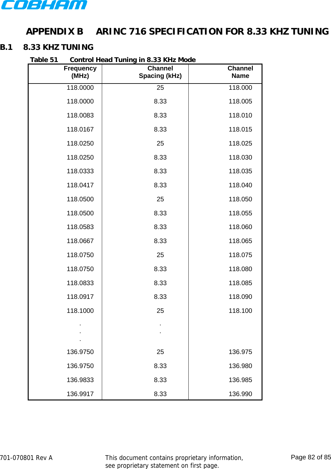
Wulfsberg Electronics Division RT7000PMR Panel Mounted Tactical Radio, Aviation and Land-Based User Manual 701 070801 A

Wulfsberg Electronics Division Panel Mounted Tactical Radio, Aviation and Land-Based 701 070801 A

User Manual

   Page 1 of 85     REVISION HISTORY  Refer to the DCA and associated markups for a complete description of the changes incorporated in a revision. REV DCA  DATE  DRAWN  CHECKED  APPROVED  PUBLISHED A W14973 07/06/15                                                                                                THIS DOCUMENT CONTAINS PROPRIETARY INFORMATION. NEITHER RECEIPT NOR POSSESSION OF THIS DOCUMENT CONFERS ANY RIGHT TO REPRODUCE, USE OR DISCLOSE, IN WHOLE OR IN PART, ANY INFORMATION CONTAINED IN THIS DOCUMENT WITHOUT WRITTEN AUTHORIZATION FROM WULFSBERG ELECTRONICS. TEMPLATE 150-744545-01 REV. E  Chelton Avionics, Inc. dba Wulfsberg Electronics Division Prescott, AZ CAGE CODE 1WZE2  A PRINTED COPY OF THIS DOCUMENT MAY NOT BE THE LATEST REVISION. IT IS THE USER’S RESPONSIBILITY TO ENSURE THAT HE OR SHE IS USING THE LATEST DOCUMENT REVISION. THE LATEST REVISION MAY BE VIEWED OR PRINTED FROM THE ELECTRONIC DOCUMENT DISTRIBUTION SYSTEM. DOCUMENT TITLE INTERFACE SPECIFICATION, HUMAN INTERFACE, RT7PAN SIZEA  LRU RT7PAN DOCUMENT NUMBER 701-070801  REV A Typed signatures indicate approval. Handwritten signature approval of this document is on file at Wulfsberg Electronics, Prescott, Arizona.  SCALE:   NONE  DO NOT SCALE DRAWING Digitally signed by: John BlasiDN: CN = John Blasi C = USDate: 2015.07.06 15:20:28 -06'00'John BlasiMichael Hohman 2015.07.06 15:25:32 -07'00'Robert Davis2015.07.06 15:26:26 -06'00'Linda Andujo signature 2015.07.06 15:53:05 -07'00'2015.07.06 15:53:27 -07'00'
   701-070801 Rev A   This document contains proprietary information, see proprietary statement on first page.  Page 2 of 85  TABLE OF CONTENTS 1PURPOSE ............................................................................................................................ 62SCOPE ................................................................................................................................. 63ACRONYMS, ABBREVIATIONS AND GLOSSARY ........................................................... 64RELATED AND REFERENCE DOCUMENTS ...................................................................... 65GUIDANCE ADHERENCE ................................................................................................... 66HUMAN INTERFACE DESCRIPTION ............................................................................... 76.1ARCHITECTURE ....................................................................................................................... 76.2POWER ON ............................................................................................................................. 86.3POWER OFF ......................................................................................................................... 106.4DISPLAY PAGES ................................................................................................................... 116.4.1Normal Operation Page .................................................................................................................................. 116.4.2System Functions ........................................................................................................................................... 336.4.3Reusable Components ................................................................................................................................... 76APPENDIX ASUB-AUDIBLE TONES ........................................................... 80A.1CTCSS TONE CODE TABLE.............................................................................................. 80A.2DCS TONE CODE TABLE ..................................................................................................  81APPENDIX BARINC 716 SPECIFICATION FOR 8.33 KHZ TUNING .................... 82B.18.33 KHZ TUNING ........................................................................................................... 82 LIST OF FIGURES Figure 1User Control Module .................................................................................................................................... 7Figure 2Display Page Tree Structure ........................................................................................................................ 8Figure 3Boot Screen ................................................................................................................................................. 9Figure 4APM-Error Screen ........................................................................................................................................ 9Figure 5Factory-Configuration-Error Screen .......................................................................................................... 10Figure 6System Shutdown Screen.......................................................................................................................... 11Figure 7Normal Operation Page ............................................................................................................................. 12Figure 8Normal Operation Page Regions ............................................................................................................... 12Figure 9Normal Operation Page Navigation ........................................................................................................... 13Figure 10Dashboard View – Internal Transceiver ................................................................................................ 14Figure 11Dashboard View – External Transceiver ................................................................................................ 14Figure 12Dashboard View – Transceiver Off ........................................................................................................ 15Figure 13Dashboard View – Transceiver Not Installed ........................................................................................ 16Figure 14Active Transceiver View ......................................................................................................................... 16Figure 15Active Transceiver View – Transceiver Off ............................................................................................ 19Figure 16Volume Adjustment Dialog .................................................................................................................... 20Figure 17QMEM Selection Dialog .......................................................................................................................... 20Figure 18Squelch Threshold Adjustment Dialog ...................................................................................................  21
   701-070801 Rev A   This document contains proprietary information, see proprietary statement on first page.  Page 3 of 85  Figure 19Changing Active Channel by Transfer ................................................................................................... 22Figure 20Changing Standby Channel by Number ................................................................................................. 22Figure 21Changing Standby Channel by Alphanumeric Identifier ........................................................................ 23Figure 22OTAR Confirmation Dialog ..................................................................................................................... 24Figure 23OTAR Status Display .............................................................................................................................. 25Figure 24OTAR Cancel Confirmation Dialog ......................................................................................................... 25Figure 25Key Selection Dialog .............................................................................................................................. 26Figure 26No Scan Groups Warning Dialog ........................................................................................................... 27Figure 27Scan Group Selection Dialog ................................................................................................................. 27Figure 28Scan Group Edit Dialog .......................................................................................................................... 28Figure 29View Channel Properties Page ............................................................................................................... 29Figure 30View Channel Properties Page Example 1 ............................................................................................. 30Figure 31View Channel Properties Page Example 2 ............................................................................................. 30Figure 32Changing Active Frequency by Transfer ................................................................................................ 32Figure 33Changing Standby Frequency by MHz ................................................................................................... 32Figure 34Changing Standby Frequency by KHz.................................................................................................... 33Figure 35Brightness Control Dialog ...................................................................................................................... 34Figure 36Mode-Selection-Menu Dialog ................................................................................................................. 34Figure 37Relay-Configuration Dialog .................................................................................................................... 35Figure 38Relay-Mode Page ................................................................................................................................... 36Figure 39Simulcast-Configuration Dialog .............................................................................................................. 37Figure 40Simulcast-Mode Page ............................................................................................................................ 38Figure 41No Message Page .................................................................................................................................. 38Figure 42Message List Page ................................................................................................................................. 39Figure 43Message View Page ............................................................................................................................... 39Figure 44Information Page ................................................................................................................................... 40Figure 44Programming-Mode-Selection Dialog .................................................................................................... 40Figure 45Programming-Password-Entry Dialog .................................................................................................... 41Figure 46Preset-Channel-Function Dialog ............................................................................................................ 42Figure 47Preset-Channel-Transceiver Page .......................................................................................................... 43Figure 48Preset-Channel-Number Page ............................................................................................................... 43Figure 49Preset-Channel-Alpha Page ................................................................................................................... 44Figure 50Preset-Channel-Type Page .................................................................................................................... 45Figure 51Preset-Channel-Receive-Frequency Page .............................................................................................. 46Figure 52Preset-Channel-Receive-Tone Page ....................................................................................................... 47Figure 53Preset-Channel-Receive-NAC Page ........................................................................................................ 47Figure 54Preset-Channel-Transmit-Frequency Page ............................................................................................ 48Figure 55Preset-Channel-Transmit-Tone Page ..................................................................................................... 49Figure 56Preset-Channel-Transmit-NAC Page ...................................................................................................... 50Figure 57Preset-Channel-Transmit-Power Page ................................................................................................... 51Figure 58Preset-Channel-Talk-Group Page .......................................................................................................... 52Figure 59Preset-Channel-Encryption-Type Page .................................................................................................. 52Figure 60Preset-Channel-Encryption-Key Page .................................................................................................... 53Figure 61Preset-Channel-Receive-Phase Page ..................................................................................................... 54Figure 62Preset-Channel-Transmit-Phase Page ................................................................................................... 55Figure 63Preset-Channel-Transmit-Deviation Page .............................................................................................. 56Figure 64Preset-Channel-Receive-Bandwidth Page .............................................................................................. 57Figure 65Preset-Channel-Save Page .................................................................................................................... 58Figure 66Delete-Preset-Channel-Transceiver Page .............................................................................................. 59Figure 67Delete-Preset-Channel-Number Page .................................................................................................... 59Figure 68Delete-Preset-Channel-Confirm Page .................................................................................................... 60Figure 69Clone-Preset-Channel-Transceiver Page................................................................................................ 61Figure 70Clone-Preset-Channel-Source Page ....................................................................................................... 61Figure 71Clone-Preset-Channel-Target Page ....................................................................................................... 61Figure 72Clone-Preset-Channel-Confirm Page ..................................................................................................... 62
   701-070801 Rev A   This document contains proprietary information, see proprietary statement on first page.  Page 4 of 85  Figure 73Scan-Group-Function Dialog .................................................................................................................. 63Figure 74Scan-Group-Add-Transceiver Page ........................................................................................................ 63Figure 75Scan-Group-Add-Number Page ............................................................................................................. 64Figure 76Scan-Group-Add-Alpha Page ................................................................................................................. 65Figure 77Scan-Group-Add-Channel-1 Page .......................................................................................................... 66Figure 78Scan-Group-Add-Priority-Channel Page ................................................................................................. 67Figure 79Scan-Group-Add-Confirm Page ..............................................................................................................  68Figure 80Scan-Group-Delete-Transceiver Page .................................................................................................... 69Figure 81Scan-Group-Delete-Number Page ......................................................................................................... 69Figure 82Scan-Group-Delete-Confirm Page .......................................................................................................... 70Figure 83Encryption-Key-Function Dialog ............................................................................................................ 71Figure 84Encryption-Key-Fill-Transceiver Page .................................................................................................... 72Figure 85Encryption-Key-Fill-Action Page .............................................................................................................  72Figure 86Encryption-Key-Erase-Transceiver Page ................................................................................................ 73Figure 87Encryption-Key-Erase-Action Page ........................................................................................................ 74Figure 90System-Configuration-Xcvr-Transceiver Page ....................................................................................... 75Figure 91System-Configuration-Xcvr-Action Page ................................................................................................ 76Figure 95Channel-Number-Entry Dialog ............................................................................................................... 77Figure 96Talk-Group-Entry Dialog ........................................................................................................................ 77Figure 97Frequency-Entry Dialog ......................................................................................................................... 78Figure 98Tone-Entry Dialog CTCSS ...................................................................................................................... 78Figure 99Tone-Entry Dialog DCS .......................................................................................................................... 79Figure 100Tone-Entry Dialog No Tone ................................................................................................................... 79 LIST OF TABLES Table 1Dashboard View Indicators ....................................................................................................................... 14Table 2Active Transceiver View Indicators ........................................................................................................... 17Table 3Transceiver Functions ............................................................................................................................... 18Table 4Channel Properties .................................................................................................................................... 31Table 5Mode-Selection-Menu Dialog Actions ........................................................................................................ 34Table 6Relay-Configuration Dialog Actions ........................................................................................................... 35Table 7Transceiver Functions in Relay-Mode ........................................................................................................ 36Table 8Simulcast-Configuration Dialog Actions ..................................................................................................... 37Table 9Programming-Mode-Selection Dialog Actions ........................................................................................... 41Table 10Preset-Channel-Function Dialog Actions ................................................................................................... 42Table 11Preset-Channel-Transceiver Page Actions ................................................................................................. 43Table 12Preset-Channel-Number Page Actions ...................................................................................................... 44Table 13Preset-Channel-Alpha Page Actions .......................................................................................................... 44Table 14Preset-Channel-Type Page Actions ........................................................................................................... 45Table 15Preset-Channel-Receive-Frequency Page Actions ..................................................................................... 46Table 16Preset-Channel-Receive-Tone Page Actions .............................................................................................. 47Table 17Preset-Channel-Receive-NAC Page Actions ............................................................................................... 48Table 18Preset-Channel-Transmit-Frequency Page Actions ................................................................................... 48Table 19Preset-Channel-Transmit-Tone Page Actions ............................................................................................ 49Table 20Preset-Channel-Transmit-NAC Page Actions ............................................................................................. 50Table 21Preset-Channel-Transmit-Power Page Actions .......................................................................................... 51Table 22Preset-Channel-Talk-Group Page Actions ................................................................................................. 52Table 23Preset-Channel-Encryption-Type Page Actions ......................................................................................... 53Table 24Preset-Channel-Encryption-Key Page Actions ........................................................................................... 53Table 25Preset-Channel-Receive-Phase Page Actions ............................................................................................ 54Table 26Preset-Channel-Transmit-Phase Page Actions .......................................................................................... 55Table 27Preset-Channel-Transmit-Deviation Page Actions ..................................................................................... 56Table 28Preset-Channel-Receive-Bandwidth Page Actions ..................................................................................... 57Table 29Preset-Channel-Save Page Actions............................................................................................................ 58
   701-070801 Rev A   This document contains proprietary information, see proprietary statement on first page.  Page 5 of 85  Table 30Delete-Preset-Channel-Confirm Page Actions ........................................................................................... 60Table 31Clone-Preset-Channel-Confirm Page Actions ............................................................................................ 62Table 32Scan-Group-Function Dialog Actions ......................................................................................................... 63Table 33Scan-Group-Add-Transceiver Page Actions ............................................................................................... 63Table 34Scan-Group-Add-Number Page Actions .................................................................................................... 64Table 35Scan-Group-Add-Alpha Page Actions ........................................................................................................ 65Table 36Scan-Group-Add-Channel-1 Page Actions ................................................................................................. 66Table 37Scan-Group-Add-Priority-Channel Page Actions ........................................................................................ 67Table 38Scan-Group-Add-Confirm Page Actions .....................................................................................................  68Table 39Scan-Group-Delete-Transceiver Page Actions ........................................................................................... 69Table 40Scan-Group-Delete-Number Page Actions ................................................................................................ 70Table 41Scan-Group-Delete-Confirm Page Actions .................................................................................................  70Table 42Encryption-Key-Function Dialog Actions ................................................................................................... 71Table 43Encryption-Key-Fill-Transceiver Page Actions ........................................................................................... 72Table 44Encryption-Key-Fill-Action Page Actions .................................................................................................... 72Table 45Encryption-Key-Erase-Transceiver Page Actions ....................................................................................... 73Table 46Encryption-Key-Erase-Action Page Actions ............................................................................................... 74Table 48System-Configuration-Xcvr-Transceiver Page Actions .............................................................................. 75Table 49System-Configuration-Xcvr-Action Page Actions ....................................................................................... 76Table 53CTCSS Tones ............................................................................................................................................. 80Table 54DCS Tones ................................................................................................................................................. 81Table 55Control Head Tuning in 8.33 KHz Mode .................................................................................................... 82End of Page 5
   701-070801 Rev A   This document contains proprietary information, see proprietary statement on first page.  Page 6 of 85  1 PURPOSE This document establishes the design requirements for the human interface of the RT-7000 panel mount radio.  It is to be used by the design team as a specification guiding all detailed design. 2 SCOPE This document addresses only the human interface of the RT-7000 panel mount radio. 3 ACRONYMS, ABBREVIATIONS AND GLOSSARY Term  Definition PMR Panel mount radio CPS  Customer Programming Software – Motorola PC application for configuring radio personality data. KVL  Key Variable Loader - Motorola product for loading encryption keys into an encryption capable radio. OTAR  Over The Air Rekeying -  an encryption system feature for loading encryption keys into a radio via a radio link. LCD  Liquid Crystal Display XCVR  Abbreviation for Transceiver APX-7000  Motorola portable radio with P25 capability APX  Abbreviation for APX-7000 CWT  Abbreviation for Cobham wideband transceiver PCIe PCI Express APM  Aircraft Personality Module 4 RELATED AND REFERENCE DOCUMENTS Document Number  Publisher  Document Title 701-070041  Wulfsberg  System Requirements Specification, RT7PAN DOT/FAA/TC-13/44 v1.0  FAA  Human Factors Considerations in the Design and Evaluation of Flight Deck Displays and Controls 701-070724 Wulfsberg Panel Mount Radio Project - Graphics, Human Factors and Haptics Guidelines  5 GUIDANCE ADHERENCE The human interface of the PMR should adhere to the applicable guidance documents as much as is practicable.  Guidance documents are listed in Section 4.  Note that the guidance documents come from multiple sources and include internally developed guidelines and those from the FAA.  The following summarizes the guidance applicable to the PMR.  This is not an exhaustive list.  The source guidance documents should be referenced when additional detail is desired.  TSOC113a Advisor Circular 25-11B SAE AS8034B Minimum Performance Standard for Airborne Multipurpose Electronic Displays SAE ARP4256A Design objectives for liquid crystal displays for part 25 (transport) aircraft
   701-070801 Rev A   This document contains proprietary information, see proprietary statement on first page.  Page 7 of 85  6 HUMAN INTERFACE DESCRIPTION The human interface of the PMR is provided by the User Control Module.  This module consists of the faceplate, knobs, buttons, LCD touch display, digital interface port, and supporting hardware.  The User Control Module communicates with the Radio Control Module over PCIe.  Figure 1 depicts the User Control Module.   HOME MENUBrightness Volume/On/Off Cursor Value/Enter Figure 1  User Control Module  6.1 ARCHITECTURE The human interface is organized into display pages.  Each display page provides the operator the ability to view specific information, or perform some specific task(s).  The operator navigates from page to page by pressing keys, turning knobs, etc.  Navigation can be achieved either through the touchscreen or through keys/knobs/push-button actions.  Display pages are organized in a tree structure, rooted at the normal operation page.  All features are three (3) actions or less from the normal operation page.  Figure 2 shows the tree structure of the display pages identified in this document.
   701-070801 Rev A   This document contains proprietary information, see proprietary statement on first page.  Page 8 of 85  NormalOperationPageBacklightBrightnessDialogOTARConfirmationDialogOTARStatusViewVolumeAdjustmentDialogEncryptionKeySelectionDialogKeypadChannelEntryDialogScanStatusViewMenuDialogSimulcastModeRelayModeRelay/SimulcastModeChannelEditDialogQMEMDialogKeypadFrequencyEntryDialogScanGroupSelect/EditDialogMessagePageConfigurationMenuRepeaterModePresetChannelsScanGroupsEncryptionKeysSystemTacticalModeViewATCModeView Figure 2  Display Page Tree Structure  6.2 POWER ON If aircraft power is removed while the PMR is in operation, the PMR shall automatically turn on upon reapplication of aircraft power.  If the PMR is not in operation (turned off) when aircraft power is removed, the PMR shall remain off when aircraft power is restored, and shall only turn on when an operator presses the “ON” button. Upon power up, the PMR shall display a “boot” screen while system initialization is taking place.  This should take less than 30 seconds, which is the amount of time specified for the transceiver modules to come up fully.  Figure 3 depicts the boot screen.  Note the software part number displayed near the bottom of the screen.  In addition, the hardware model number and firmware number shall be displayed.
   701-070801 Rev A   This document contains proprietary information, see proprietary statement on first page.  Page 9 of 85  320-1XXXXX-XX Figure 3  Boot Screen  During power up, if the Aircraft-Personality-Module (APM) is missing or inoperable, the PMR shall display an error screen indicating the condition.  The operator shall be required to acknowledge this condition before execution can continue.  Once acknkowledged, the system shall use default values for the APM parameters and continue the boot process.  Figure 4 depicts the APM-Error screen. Configurationmoduleerror.Missingorinoperable.Usingdefaultvalues. Figure 4  APM-Error Screen  During power up, if the Factory-Configuration data is missing or corrupt, the PMR shall display an error screen indicating the condition and cease normal operation.  Figure 5 depicts the Factory-Configuration-Error screen.
   701-070801 Rev A   This document contains proprietary information, see proprietary statement on first page.  Page 10 of 85   Figure 5  Factory-Configuration-Error Screen  6.3 POWER OFF If aircraft power is removed while the PMR is in operation, the PMR shall be able to restore the following from non-volatile memory upon reapplication of aircraft power.  Current active channel for each transceiver  Current volume level for each transceiver  Current active transceiver  Audio Levels The operator shall be able to turn the PMR off by pressing and holding the “ON” button.  While the “ON” button is being held down, the PMR shall do the following: 1. Go to full brightness. 2. Display the System Shutdown screen depicted in Figure 6. 3. Count down the seconds remaining until system turns off from 3 to 0. 4. When the count hits 0, power off. If the operator releases the “ON” button prior to 3 seconds elapsing, the display shall return its previous state.
   701-070801 Rev A   This document contains proprietary information, see proprietary statement on first page.  Page 11 of 85   Figure 6  System Shutdown Screen  6.4 DISPLAY PAGES The following sections flesh out each of the display pages identified in Figure 2.  The information required to display on each page is given along with known button/knob event requirements.  A picture showing the desired page layout is also provided.  Due to the significant differences in aspect ratio between the documentation system and the actual hardware’s display, some deviation in fonts, colors, and information placement is expected, and permissible, in the implementation. 6.4.1 NORMAL OPERATION PAGE This page is the primary operational page of the PMR.  This page shall be the first operational page displayed after system boot.  Figure 7 depicts the desired layout for this page when the maximum 5 transceivers are available. 6.4.1.1 Layout
   701-070801 Rev A   This document contains proprietary information, see proprietary statement on first page.  Page 12 of 85  125.300RT2CHINO FDRT3RT161 PRESCOTT TWR174 WEATHERCHAN MUTE DIRSCANPVTDIRRXDIR PVT SCANRX◄◄RT4 RT5RT1PRESCOTT TWR Figure 7  Normal Operation Page  The Normal-Operation-Page is divided into 2 regions: System Dashboard and Active Transceiver.  These regions are depicted in Figure 8. PRESCOTT TWRRT1125.300RT2CHINO FDRT3RT161 PRESCOTT TWR174 WEATHERCHAN MUTE DIRSCANPVTDIRRXDIR PVT SCANRX◄◄ActiveTransceiverSystemDashboardRT5RT4 Figure 8  Normal Operation Page Regions  The System-Dashboard region contains a summary of the operating state of all the transceivers installed in the system.  The PMR supports from 1 to 3 internal transceivers and 0 to 2 external transceivers.  This region shall be split into sub-regions, one for each transceiver.  These sub-regions are termed a Dashboard-View.  Details of the contents of the Dashboard-View are given elsewhere in this document. The Active-Transceiver region contains detailed information on the active transceiver.  The active transceiver is the one that the operator will interact with.  This region of the display is termed an Active-Transceiver-View.  All transceiver specific functions are accessed via the Active-Transceiver-View.  Details of the contents of the Active-Transceiver-View are given elsewhere in this document.
   701-070801 Rev A   This document contains proprietary information, see proprietary statement on first page.  Page 13 of 85  A transceiver shall be made active by pressing its Dashboard-View, either by direct touch or by cursor/value/enter.  Any of the installed transceivers shall be selectable as the active transceiver, but only one transceiver shall be active at any given time.   When a transceiver is made active, it shall become the active transmitter for its PTT group.  In single-microphone installations (i.e. a single PTT group), the active transceiver shall transmit when the PTT is asserted.  In multiple-microphone installations (i.e. two or more PTT groups), the active transceiver for the PTT group shall transmit when the PTT for the group is asserted. 6.4.1.2 Navigation To Home page shall be navigable by both touch and cursor/value.  The screen element that the operator is currently interacting with shall be indicated by a rectangle drawn around the element.  This rectangle is termed the focus rectangle.  Only one screen element shall be focused at any given time.  After three (3) seconds of inactivity, the focus rectangle shall become invisible to avoid screen clutter.  The gold boxes (some rounded) in Figure 9 show the screen elements that shall be focusable. Touching an element gives it the focus.  Rotating the cursor knob clockwise shall move the focus rectangle in a generally circular, left-to-right, top-to-bottom fashion.  The red arrows in Figure 9 depict the motion of the focus rectangle as the cursor knob is turned clockwise.  Turning the cursor knob counterclockwise shall move the focus rectangle in the reverse order of clockwise rotation.  If the focus rectangle is invisible due to inactivity, the first turn of the cursor knob shall make the focus rectangle visible, but shall not move it from its previous location.  Figure 9  Normal Operation Page Navigation  6.4.1.3 Dashboard-View The Dashboard-View contains a summary of the operating state of a transceiver.  Its purpose is to keep the operator informed about the state of non-active transceivers.  This view contains only summary information, such as the active channel and indications of mode.  The Dashboard-View for an internal transceiver is depicted in Figure 10.  The Dashboard-View for an external transceiver is depicted in Figure 11.
   701-070801 Rev A   This document contains proprietary information, see proprietary statement on first page.  Page 14 of 85  ACT--CHANNELRTX RX TX PTXDIR PVT SCANSIM RLY Figure 10  Dashboard View – Internal Transceiver  RTXRX TXPTXSIM RLY Figure 11  Dashboard View – External Transceiver  Table 1  Dashboard View Indicators Indicator  Description RTX  Placeholder for transceiver’s identifier.  Always visible. Valid values are RT1, RT2 … RT5 RX  Indicates transceiver is receiving.  Only visible when receiving. TX  Indicates transceiver is transmitting.  Only visible when transmitting. PTX Indicates transceiver is associated with PTT-X.  Displayed in reverse video (as shown) when transceiver is the active transceiver for its PTT group.  Can change if transceiver is participating in a simulcast, in which case the simulcast trigger PTT will be displayed. DIR Indicates transceiver is in direct mode.  Only visible when transceiver is in direct mode.  When not displayed, transceiver is in repeater mode.  This indicator should automatically appear for preset channels whose transmit and receive frequencies are identical.
   701-070801 Rev A   This document contains proprietary information, see proprietary statement on first page.  Page 15 of 85  PVT  Indicates transceiver is in private mode, i.e. encryption is enabled.  Only visible when transceiver is in encrypted mode.  When not displayed, transceiver is operating in the clear. SCAN  Indicates transceiver is in scan mode.  Only visible when transceiver is in scan mode.  When not displayed, transceiver is not scanning. SIM Indicates transceiver is participating in a simulcast.  Only visible when simulcast mode is active and the transceiver is participating in the simulcast.  When not displayed, transceiver is not participating in a simulcast. RLY  Indicates transceiver is participating in a relay.  Only visible when relay mode is active and transceiver is participating in the relay.  When not displayed, transceiver is not participating in a relay. ACT--CHANNEL Placeholder for transceiver’s active channel.  Always visible.  When transceiver is in tactical mode and is tuned to a preset channel the active channel indicator will display the alphanumeric identifier of the channel.  When transceiver is in COM mode, or the manual channel is tuned while in tactical mode, the active channel indicator will display the receive frequency of the channel.  When the transceiver has been turned off, all indicators except the transceiver identifier shall be invisible, and “RADIO OFF” shall be displayed.  The Dashboard-View for a transceiver that is off is depicted in Figure 12.  Figure 12  Dashboard View – Transceiver Off  When the transceiver is not installed in the system, all indicators except the transceiver identifier shall be invisible, and “NOT INSTALLED” shall be displayed.  The Dashboard-View for a transceiver that is not installed is depicted in Figure 13.
   701-070801 Rev A   This document contains proprietary information, see proprietary statement on first page.  Page 16 of 85  RTXNOT INSTALLED Figure 13  Dashboard View – Transceiver Not Installed  6.4.1.4 Active-Transceiver-View The Active-Transceiver-View contains detailed information on the operating state of the active transceiver, and allows the operator to control the transceiver.  From within this view the operator can perform activities such as change channels, enter/exit direct mode, turn on/off encryption, etc.  This also contains more detailed state information than is displayed in the Dashboard-View.  The Active-Transceiver-View is depicted in Figure 14.  Figure 14  Active Transceiver View  The Transceiver-Label contains the identifier of the active transceiver.  Valid values are RT1, RT2, RT3, RT4, and RT5.  The Transceiver-Label shall behave as a button that when pressed, shall toggle the transceiver’s on/off state.  The label press shall be either by direct touch, or by cursor/value/enter control. The Indicator-Bar displays the current state of the active transceiver.  The following table lists all the indicators that can appear in the Indicator-Bar, what they mean, and when they are to be displayed.
   701-070801 Rev A   This document contains proprietary information, see proprietary statement on first page.  Page 17 of 85   Table 2  Active Transceiver View Indicators Indicator  Description RX  Indicates transceiver is receiving.  Only visible when receiving. TX  Indicates transceiver is transmitting.  Only visible when transmitting. M  Indicates transceiver is muted.  Only visible when muted. 90%  Placeholder for current volume level.  Always visible.  Valid values range from 0% to 100%. DIR Indicates transceiver is in direct mode.  Only visible when transceiver is in direct mode.  When not displayed, transceiver is in repeater mode.  This indicator should automatically appear for preset channels whose transmit and receive frequencies are identical. PVT  Indicates transceiver is in private mode, i.e. encryption is enabled.  Only visible when transceiver is in encrypted mode.  When not displayed, transceiver is operating in the clear. SCAN  Indicates transceiver is in scan mode.  Only visible when transceiver is in scan mode.  When not displayed, transceiver is not scanning. SIM Indicates transceiver is participating in a simulcast.  Only visible when simulcast mode is active and the transceiver is participating in the simulcast.  When not displayed, transceiver is not participating in a simulcast. RLY  Indicates transceiver is participating in a relay.  Only visible when relay mode is active and transceiver is participating in the relay.  When not displayed, transceiver is not participating in a relay. PTX Indicates transceiver is associated with PTT-X.  Displayed in reverse video (as shown) when transceiver is the active transceiver for its PTT group.  Can change if transceiver is participating in a simulcast, in which case the simulcast trigger PTT will be displayed.  The Transfer-Button is a soft button that allows the operator to flip-flop the active and standby channels.  The Transfer-Button shall only be visible when the active transceiver is operating in standby tuning mode. The Active-Channel-Field is always visible and displays the channel to which the active transceiver is currently tuned.  When operating in Tactical-Mode the Active-Channel-Field shall display the channels number and alphanumeric identifier if tuned to a preset channel.  In SCAN mode, this field will display the active channel.  When Paused or Delaying in SCAN mode, this field will display the channel where the pause or delay occurs. If tuned to a manual channel, the number shall be displayed as ‘..M’ and the channel’s receive frequency shall be displayed in place of the alphanumeric identifier.  If the PTT is in effect, the alphanumeric identifier shall change to the transmit frequency of the channel, and if the channel is being encrypted, the encryption key shall be displayed to the right of the transmit frequency.  If the channel is for receive only, the alphanumeric identifier field shall display “RX ONLY” during an attempted PTT.  When operating in ATC-Mode the Active-Channel-Field shall display the channel’s receive frequency. The Standby-Channel-Field is only visible in standby tuning mode, and displays the channel to which the active transceiver will be tuned when the Transfer-Button is pressed.  When operating in Tactical-Mode the Standby-Channel-Field shall display the channels number and alphanumeric identifier if tuned to a preset channel.  If tuned to a manual channel, the number shall be displayed as ‘..M’ and the channel’s receive frequency shall be displayed in place of the alphanumeric identifier.  When operating in ATC-Mode the Standby-Channel-Field shall display the channel’s receive frequency. The Transceiver-Function-Menu is always visible and displays the functions available for the active transceiver.  Different types of transceivers have different functions.  Only functions applicable to the active transceiver shall be made visible.  Functions that are applicable but not available shall be shown but disabled.  The following table lists the transceiver functions and their applicability.
   701-070801 Rev A   This document contains proprietary information, see proprietary statement on first page.  Page 18 of 85  Table 3  Transceiver Functions Function  Description  Applicability  Mode  Availability CHAN  Allows channel to be selected by channel number  APX, CWT  TAC  Always DIR  Toggles state of direct/repeat mode  APX, CWT  TAC  Only when channel is duplex OTAR  Start/Stop performing an OTAR operation  APX, CWT  TAC  Only when encryption is available KEY  Allows encryption key to be temporarily changed  APX, CWT  TAC  Only when encryption is available TEST  Temporarily forces un-squelch of transceiver  APX, CWT  TAC, ATC  Always SCAN Start/Stop scanning  APX, CWT  TAC  Only when scan groups defined for transceiver PVT  Toggles encryption on/off  APX, CWT  TAC  Only when encryption is available EDIT Allows temporarily overriding some channel parameters, such as sub-audible tones, NAC codes, transmit power levels, etc. APX, CWT  TAC  Always QMEM  Displays quick-memory preset channels  APX, CWT  TAC, ATC  Always VOL  Allows changing transceiver’s volume level  APX, CWT  TAC, ATC  Always ATC  Allows toggling transceiver’s operating mode between ATC COM and Tactical. CWT TAC, ATC  Always FREQ  Allows frequency to be selected by number  CWT ATC Always MUTE  Toggles state of mute, allowing audio to be heard or silenced.  APX, CWT  TAC, ATC  Always 25K  Force COM tuning to be in 25 KHz increments.  CWT ATC Always 8.3K  Force COM tuning to be in 8.33 KHz increments.  CWT ATC Always SQL  Allows squelch threshold to be changed.  CWT TAC, ATC  Always  When the transceiver has been turned off, all indicators except the transceiver identifier shall be invisible, and “RADIO OFF” shall be displayed.  The Active-Transceiver-View for a transceiver that is off is depicted in Figure 15.
   701-070801 Rev A   This document contains proprietary information, see proprietary statement on first page.  Page 19 of 85   Figure 15  Active Transceiver View – Transceiver Off  6.4.1.5 Common Functions Some functionality is available regardless of whether a transceiver is operating in Tactical mode or ATC-COM mode, such as volume control.  The following sections describe operation that is common to both Tactical and ATC-COM mode. 6.4.1.5.1 Test Function When the operator presses and holds the TEST Transceiver-Menu button the active transceiver shall be forcibly un-squelched for as long as the button is pressed.  When the operator releases the Transceiver-Menu button, the active transceiver shall resume its normal squelch operation. 6.4.1.5.2 Mute Function When the operator presses the MUTE Transceiver-Menu button the active transceiver shall be muted if it is not already muted, and shall become unmuted if it is currently muted.  When a transceiver is muted, no audio from that transceiver shall be audible. 6.4.1.5.3 Volume Adjustment When the operator turns the volume knob, the volume adjustment dialog shall appear to adjust the volume on the active transceiver.  Figure 16 depicts the volume adjustment dialog after the volume knob has been turned.  Turning the volume knob clockwise shall increase the volume level, while turning the knob counter clockwise shall decrease the volume level.  The current volume level shall be displayed within the dialog.  The volume adjustment dialog shall automatically disappear when no knob turning activity has occurred for more than 2 seconds. When the operator pushes the VOL Transceiver-Menu button the volume adjustment dialog shall appear to adjust the volume on the active transceiver.  Touching the volume scale and sliding the pointer to the left shall decrease the volume level, while sliding the pointer to the right shall increase the volume level.  The current volume level shall be displayed within the dialog.  The volume adjustment dialog shall automatically disappear when no touch pointer activity has occurred for more than 2 seconds.
   701-070801 Rev A   This document contains proprietary information, see proprietary statement on first page.  Page 20 of 85  RT1VOL: 90%90%CHAN MUTE VOLPVTDIR◄◄90%90% Figure 16  Volume Adjustment Dialog  6.4.1.5.4  Quick Memory (QMEM) The QMEM feature allows the operator to store/recall frequencies much like presets on a car stereo.  When the operator presses the QMEM Transceiver-Menu button, the QMEM selection dialog shall be displayed.  The QMEM selection dialog allows the operator to either recall or program a QMEM location.  When the operator momentarily presses a QMEM location, the channel programmed into the corresponding (0-9) QMEM location shall be loaded into the active channel, and the previously active channel shall be loaded into the standby channel.  If the operator presses and holds a QMEM location (0-9) for 3 or more seconds, the current active channel shall be programmed into the corresponding QMEM location.  Should the operator not press any key for more than 4 seconds after pressing the QMEM Transceiver-Menu button, the QMEM operation shall automatically be canceled.  The operator shall be able to manually cancel the QMEM operation by pressing the Cancel button.  There shall be 10 QMEM locations for Tactical mode, and another 10 QMEM locations for ATC-COM mode.  Figure 17 depicts the QMEM selection dialog in Tactical Mode. Select QMEM0: PRESCOTT TWR2: CHINO FD4: N/A6: N/A8: N/ACancel1: WEATHER3: PRESCOTT PD5: N/A7: N/A9: N/A Figure 17  QMEM Selection Dialog
   701-070801 Rev A   This document contains proprietary information, see proprietary statement on first page.  Page 21 of 85  When a transceiver is operating in Tactical mode the QMEM selection dialog shall display the alphanumeric identifier of the preset channel if the QMEM locations has been programmed or “N/A if the locations is un-programmed.  When a transceiver is operating in ATC-COM mode, the receive frequency of the channel shall be displayed for programmed QMEM locations, while “N/A” shall be displayed for un-programmed locations. The QMEM locations can be touched directly, or selected by rotation the Cursor knob.  The selected locations shall be indicated by the focus rectangle, shown in orange in the figure.  Pressing the ENTER button shall have the same effect on the focused location as if it were touched directly on the screen, including the press and hold functionality. 6.4.1.5.5  Squelch Threshold Adjustment When the operator pushes the SQL Transceiver-Menu button the squelch threshold adjustment dialog shall appear to adjust the squelch threshold on the active transceiver.  Touching the scale and sliding the pointer to the left shall decrease the level, while sliding the pointer to the right shall increase the level.  Rotating the value knob clockwise shall increase the level while rotating the value knob counterclockwise shall decrease the level.  The current level shall be displayed within the dialog.  The squelch threshold adjustment dialog shall automatically disappear when no touch pointer activity has occurred for more than 2 seconds.  Figure 18 depicts the squelch threshold adjustment dialog after the SQL button has been pressed. RT1SQL: 25%90%MUTE VOL SQLPVTDIR◄◄90% Figure 18  Squelch Threshold Adjustment Dialog  6.4.1.6 Tactical Mode When a transceiver is operating in Tactical mode it behaves similar too, and has all the functionality of, previous generations of Cobham (Wulfsberg) tactical radios, such as the C-5000/RT-5000 and P-2000.  This includes preset channel tuning, P25 functionality, and, via the Manual-Channel, unlimited frequency tuning capability.  The following sections describe operation in Tactical mode. 6.4.1.6.1 Changing Channels When the unit is operating in tactical mode and standby tuning is enabled and the operator presses the Transfer-Button the active and standby channels shall be swapped, and the active transceiver shall be tuned to the new active channel (previously the standby channel).  Figure 19 depicts the active transceiver both prior to, and after, pressing the Transfer-Button.
   701-070801 Rev A   This document contains proprietary information, see proprietary statement on first page.  Page 22 of 85   Figure 19  Changing Active Channel by Transfer  When the unit is operating in tactical mode and standby tuning is enabled the operator shall be able to focus the standby channel’s Channel-Number field.  When the Channel-Number field has the focus, turning the Value knob clockwise shall select the next available channel by number, while turning the knob counterclockwise shall select the previous available channel by number.  Figure 20 depicts the standby channel being tuned by number.  Figure 20  Changing Standby Channel by Number  When the unit is operating in tactical mode and standby tuning is enabled the operator shall be able to focus the standby channel’s Channel-Alpha field.  When the Channel-Alpha field has the focus, turning the Value knob clockwise shall select the next available channel by alphanumeric identifier, while turning
   701-070801 Rev A   This document contains proprietary information, see proprietary statement on first page.  Page 23 of 85  the knob counterclockwise shall select the previous available channel by alphanumeric identifier.  Figure 21 depicts the standby channel being tuned by alphanumeric identifier.  Figure 21  Changing Standby Channel by Alphanumeric Identifier  When the unit is operating in tactical mode and standby tuning is enabled and the operator presses the CHAN Transceiver-Menu button, the Channel-Number-Entry dialog shall appear to change the standby channel on the active transceiver.  Figure 91 depicts the Channel-Number-Entry dialog. If the number entered is a valid channel, it shall be loaded into the active transceiver and the display shall return to the Normal-Operation-Page.  If the entered number is invalid, the digits entered shall be cleared and the operator can try again.  Entering a channel number of 0 shall load the manual channel for the active transceiver.  Pressing the HOME button shall cancel the operation and return to the Normal-Operation-Page. 6.4.1.6.2 Direct/Repeat Mode When the unit is operating in tactical mode and the active channel is not a simplex channel, and the operator presses the DIR Transceiver-Menu button and the transceiver is in Direct mode, the transceiver shall change to Repeater mode.  Conversely, if the transceiver is in Repeater mode, pressing the DIR Transceiver-Menu button shall change the transceiver to Direct mode.  If the active channel is a simplex channel, the DIR Transceiver-Menu button shall have no effect as DIR should be displayed at all times 6.4.1.6.3 Encrypted Mode When the unit is operating in tactical mode and the active channel is capable of encryption, and the operator presses the PVT Transceiver-Menu button and the transceiver is in encrypted mode, the transceiver shall change to non-encrypted mode.  Conversely, if the transceiver is in non-encrypted mode, pressing the PVT Transceiver-Menu button shall change the transceiver to encrypted mode.  If the active channel (or transceiver itself) is not capable of encryption, the PVT Transceiver-Menu button shall have no effect. 6.4.1.6.4 ATC Mode When the unit is operating in tactical mode and the operator presses the ATC Transceiver-Menu button, the transceiver shall change to ATC-COM mode.  Note ATC-COM functionality is only available on CWT modules.  If the active transceiver is an APX, the ATC Transceiver-Menu button should be disabled or invisible. 6.4.1.6.5 OTAR Process When the operator presses the OTAR Transceiver-Menu button, the OTAR process shall begin.  The first step in this process is confirmation.  The operator shall be presented with the OTAR start confirmation dialog, depicted in Figure 22.  The operator may press the NO button or the HOME key to cancel the operation, or press the YES button to continue the OTAR operation.
   701-070801 Rev A   This document contains proprietary information, see proprietary statement on first page.  Page 24 of 85   Figure 22  OTAR Confirmation Dialog  Once the operator has confirmed the operation, the active transceiver shall begin the OTAR operation.  The display shall give feedback to the operator on the progress of the OTAR operation.  At a minimum, “OTAR in progress” and “OTAR completed” or “OTAR failed” status messages shall be displayed.  The status messages shall be displayed in the screen area normally used to display the active and standby channel information.  Figure 23 depicts a typical OTAR status display. While the OTAR status is “OTAR in progress” the STOP button shall be enabled. If the operator presses the STOP button the OTAR cancel confirmation dialog shall be displayed, as depicted in Figure 24.  This dialog functions identically to the OTAR start confirmation dialog.  If the operator chooses to cancel the OTAR, then the OTAR operation shall be aborted and normal operation resumed.  If the operator chooses to continue with the OTAR operation, the display shall resume to where it was prior to the STOP button being pressed.  While an OTAR is in progress, no transceiver functions shall be available other than to cancel the OTAR in progress. While the OTAR status is “OTAR completed” or “OTAR failed” the OK button shall be enabled. The operator shall be required to press the OK button to acknowledge the result of the OTAR operation.  When the operator presses the OK button the display and available functionality shall return to normal.
   701-070801 Rev A   This document contains proprietary information, see proprietary statement on first page.  Page 25 of 85  RT1OTAR failed!OKSCANPVTDIR90%RT1OTAR completeOKSCANPVTDIR90%RT1OTAR in progressCANCELSCANPVTDIR90% Figure 23  OTAR Status Display  Figure 24  OTAR Cancel Confirmation Dialog
   701-070801 Rev A   This document contains proprietary information, see proprietary statement on first page.  Page 26 of 85  6.4.1.6.6 Encryption Key Selection When the operator presses the KEY Transceiver-Menu button, the encryption key selection dialog shall appear as depicted in Figure 25.  All 16 possible keys shall be displayed, both by number and alphanumeric identifier.  In addition, the “PRESET” option shall be displayed, allowing the restoration of the key that was preset for the channel.  The operator shall be able to select a key by touching it directly on the screen, or by using the cursor/value knobs.  When the value knob is turned, the focus rectangle shall traverse the list, scrolling as necessary.  When the cursor knob is turned, the focus rectangle shall move between the list and the Cancel button.  Pressing the ENTER button shall select the key with the focus.  The operator shall be able to cancel the operation by pressing the Cancel button. Select KeyP: PRESET2: IOP DES3: DES 31: DES 1CancelOk Figure 25  Key Selection Dialog  6.4.1.6.7 Scan Operation Scan mode is invoked by pressing the SCAN Transceiver-Menu button.  Only the active transceiver is affected.  If the active transceiver is incapable of scan, the Error-Tone should sound.  If the active transceiver is scan capable but there are no scan groups programmed for it, the No-Scan-Groups dialog shall display.  If the active transceiver is scan capable and there are one or more scan groups programmed for it, the Select-Scan-Group dialog shall display.  The No-Scan-Groups dialog is displayed when an attempt is made to start scan mode on a transceiver that has no scan groups associated with it.  The page is depicted in Figure 26.  The OK soft button or the HOME button shall be used to dismiss the dialog.  All other buttons and knobs are ignored.  The Select-Scan-Group dialog is displayed when scan mode is started on a transceiver that has one or more associated scan groups.  This page, depicted in Figure 27, shall allow the operator to select one of the transceiver’s scan groups for scanning. The first time the Select-Scan-Group dialog is displayed after a power cycle, the first (lowest numbered) scan group assigned to the active transceiver shall be focused.  For subsequent invocations of the page, the most recently selected scan group for the active transceiver shall be focused.  The last selected scan group need not be retained when power is lost. All available scan groups for the transceiver shall be displayed, both by number and alphanumeric identifier.  The operator shall be able to select a group by touching it directly on the screen, or by using the cursor/value knobs.  When the value knob is turned, the focus rectangle shall traverse the list, scrolling as necessary.  When the cursor knob is turned, the focus rectangle shall move between the list and the Edit, Scan, and Cancel buttons.
   701-070801 Rev A   This document contains proprietary information, see proprietary statement on first page.  Page 27 of 85  Pressing the Cancel soft-button or the HOME button shall return the system to the Home page in normal operating mode.  Pressing the Scan soft-button shall return the system to the Home page with the active transceiver in scan mode.  Pressing the Edit soft-button shall invoke the Scan-Group-Edit dialog.  Figure 26  No Scan Groups Warning Dialog  Select Group1: FIRE3: HOMELAND4: N/A2: POLICECancelEdit Scan Figure 27  Scan Group Selection Dialog  The Scan-Group-Edit dialog, depicted in Figure 28, allows the operator to temporarily remove (or restore) a channel from the group, providing a nuisance delete feature.  This dialog also allows the operator to temporarily change the priority 2 channel assignment for the group.  Any changes made on this page shall be lost after a power cycle. All channels in the scan group shall be displayed, both by number and alphanumeric identifier.  The operator shall be able to select whether a channel is included in the scan via a toggle button or checkbox, or equivalent.  This is depicted as a square in the figure, where green means the channel will be scanned, white means the channel will be excluded.  The operator shall also be able to select which channel, if any, is the priority-2 channel.  This should be done via a set of radio buttons, or equivalent.  This is depicted as a circle in the figure.  Only one channel can be the priority-2 channel, but the priority-2 channel is not required.
   701-070801 Rev A   This document contains proprietary information, see proprietary statement on first page.  Page 28 of 85  Pressing the Back soft-button or the HOME button shall return the system to the Scan-Group-Selection dialog.  Pressing the Scan soft-button shall return the system to the Home page with the active transceiver in scan mode. TBD – How to navigate this by cursor/value?  Note that selecting 1 of the 10 channels for priority channel is inconsistent with the scan-group FPP pages. Edit Group #1Back Scan100 PRESCOTT TWR101 WEATHER102 CHINO FD105 PRESCOTT PD Figure 28  Scan Group Edit Dialog  When the operator presses the “Scan” button on the Select-Scan-Group page, the system will return to the Home page with the active transceiver scanning the selected group.  The active channel of the active transceiver shall be automatically added to the selected scan group as the priority-1 channel.  The system shall indicate it is scanning by displaying an the SCAN indicator. If the system detects a signal while scanning, the display shall indicate the reception by displaying the SCAN indicator in reverse video.  Furthermore, the channel being received shall be displayed temporarily in place of the active channel. The display shall revert to showing the active channel when the signal has been lost from the scan channel for more than a prescribed amount of time.  This time delay, called scan-delay, shall be programmable with a default of 3 seconds. If the operator while the system is scanning, and the transceiver being scanned is the active transceiver, and one of the scan channels is currently receiving, the scan channel being received shall be temporarily removed from the scan group.  This is a convenience function that is equivalent to changing the IN/OUT status of the channel via Scan-Group-Edit page.  The channel can be added back into the group using the Scan-Group-Edit page. If the operator presses PTT while the system is scanning, and the transceiver being scanned is the active transceiver, and no scan channel is currently receiving, the system shall stop scanning, and then proceed to transmit on the active channel.  The system shall automatically resume scanning after 3 seconds of inactivity on the active channel. If the operator presses PTT while the system is scanning, and the transceiver being scanned is the active transceiver, and one of the scan channels is currently receiving, the system shall stop scanning, and then proceed to transmit on the currently active scan channel.  The system shall automatically resume scanning after 3 seconds of inactivity on the active scan channel.  This provides a talkback feature.
   701-070801 Rev A   This document contains proprietary information, see proprietary statement on first page.  Page 29 of 85  If the operator presses PTT while a non-scanning transceiver is active, the transceiver being scanned shall remain scanning. If the operator changes channel on a scanning transceiver, the newly tuned channel shall become the active channel and the system shall continue scanning.  If the operator changes channel on a non-scanning transceiver, the transceiver being scanned shall remain scanning. If the operator presses the SCAN Transceiver-Menu button, the system shall stop scanning and display the Select-Scan-Group page.  This allows the operator to quickly select another group to scan, edit the selected scan group, or exit scan mode completely. 6.4.1.6.8  View Channel Properties Page The View-Channel-Properties page shall allow the user to view all known properties of any channel known to the transceiver.  The transceiver whose channels are being displayed shall be identified.  Channel properties expected to be displayed are detailed in Table 4.  Figure 29 depicts the desired layout for this page. PRESCOTT TWRPropertyList ScrollBarTitleBar RT1 Preset 105105Channel Number◄◄PRESCOTT TWRAlphanumeric ID138.125Receive Frequency138.125Transmit Frequency273Receive NAC273Transmit NACStandardReceive Bandwidth25.0 KhzTransmit Deviation Figure 29  View Channel Properties Page
   701-070801 Rev A   This document contains proprietary information, see proprietary statement on first page.  Page 30 of 85  PRESCOTT TWRRT1 Preset 105105Channel NumberPRESCOTT TWRAlphanumeric ID138.125Receive Frequency138.125Transmit Frequency293Receive NAC293Transmit NACStandardReceive Bandwidth2.5 KhzTransmit Deviation Figure 30  View Channel Properties Page Example 1 PRESCOTT TWRRT1 Preset 105P25Receive ModulationHighTransmit Power0 DegreesReceive Phase0 DegreesTransmit Phase65535Talk GroupDES 5Encryption Key Figure 31  View Channel Properties Page Example 2
   701-070801 Rev A   This document contains proprietary information, see proprietary statement on first page.  Page 31 of 85   Table 4  Channel Properties Property  Values  Applicability  Editable  Availability Channel Number  Integer  APX, CWT  Never  Always Alphanumeric Identifier  String  APX, CWT  Never  Always Receive Frequency  Real Number  APX, CWT  Manual  Always Transmit Frequency  Real Number  APX, CWT  Manual  Always Receive Tone  See Appendix A  APX, CWT  Always  Conventional FM channel Transmit Tone  See Appendix A  APX, CWT  Always  Conventional FM channel Receive Network Access Code  3-digit hexadecimal  APX, CWT  Always  P25 channel Transmit Network Access Code  3-digit hexadecimal  APX, CWT  Always  P25 channel Receive Modulation Type  FM, AM, P25, Trunked  APX, CWT  Manual  Always Receive Bandwidth  Narrow, Standard, Wide  APX, CWT  Manual  Always Transmit Power  High, Low  APX, CWT  Always  Always Encryption Key  Integer  APX, CWT  Manual  P25 channel Zone Integer  APX Never Always Zone Channel  Integer  APX  Never  Always Talk Group  Integer  APX, CWT  Always  P25 channel Transmit Deviation  2.5K, 4.0K, 5.0K, 5.6K  APX, CWT  Manual  Always Transmit Phase  0, 180  CWT  Manual  Always Receive Phase  0, 180  CWT  Manual  Always OTAR Capable  True, False  APX, CWT  Manual  P25 channel  When the receive frequency is changed, the transmit frequency shall be set equal to it, easing normal simplex channel entry.  Entering a receive frequency between 108 and 137 MHz or between 225 and 400 MHz shall automatically change the modulation type to AM, unless the modulation type is P25 or TRK.  Entering any other receive frequency shall force the modulation to FM, unless the modulation type is P25 or TRK.  Frequency entry shall be accomplished via the Frequency-Entry dialog depicted in Figure 93. CTCSS tones shall be displayed using their 2-digit EIA code.  DCS tones shall be displayed as a 3-digit number, padded with a leading zero if required.  The word “None” shall indicate no tone is in use.  The Tone fields shall only be visible when the channel type is “FM”.  Tone entry shall be accomplished via the Tone-Entry dialog depicted in Figure 94. Encryption keys shall be displayed using their alphanumeric identifier.  Encryption key entry shall be accomplished via the Key-Selection dialog depicted in Figure 25.  6.4.1.7 ATC COM Mode When a transceiver is operating in ATC-COM mode it behaves similar too, and has all the functionality of, previous generations of Cobham (Wulfsberg) COM radios, such as the CVC-152/CVC-151 and CD-5000/RT-5000.  This includes frequency tuning limited to the AM COM bands.  The following sections describe operation in ATC-COM mode. 6.4.1.7.1 Changing Frequencies When the unit is operating in ATC-COM mode and standby tuning is enabled and the operator presses the Transfer-Button the active and standby frequencies shall be swapped, and the active transceiver
   701-070801 Rev A   This document contains proprietary information, see proprietary statement on first page.  Page 32 of 85  shall be tuned to the new active frequency (previously the standby frequency).  Figure 32 depicts the active transceiver both prior to, and after, pressing the Transfer-Button.  RT1121.500127.3008.3K TEST 25K◄◄90%RT1127.300121.5008.3K TEST 25K◄◄90% Figure 32  Changing Active Frequency by Transfer  When the unit is operating in ATC-COM mode and standby tuning is enabled the operator shall be able to focus the standby frequency’s megahertz field.  When the megahertz field has the focus, turning the Value knob clockwise shall increment the frequency by 1 MHz, while turning the knob counterclockwise shall decrement the frequency by 1 MHz.  Figure 33 depicts the standby frequency being tuned by MHz.  Figure 33  Changing Standby Frequency by MHz
   701-070801 Rev A   This document contains proprietary information, see proprietary statement on first page.  Page 33 of 85  When the unit is operating in ATC-COM mode and standby tuning is enabled the operator shall be able to focus the standby frequency’s kilohertz field.  When the kilohertz field has the focus and the transceiver is in 25K mode, turning the Value knob clockwise shall increment the frequency by 25.0 KHz, while turning the knob counterclockwise shall decrement the frequency by 25.0 KHz.  When the kilohertz field has the focus and the transceiver is in 8.3K mode, turning the Value knob clockwise shall increment the frequency by 8.33 KHz, while turning the knob counterclockwise shall decrement the frequency by 8.33 KHz.  Note that the displayed frequency and actual frequency are not the same when in 8.3K mode.  Refer to Appendix B for more information.  Figure 34 depicts the standby frequency being tuned by KHz.  Figure 34  Changing Standby Frequency by KHz  When the unit is operating in ATC-COM mode and standby tuning is enabled and the operator presses the FREQ Transceiver-Menu button, the Frequency-Entry dialog shall appear to change the standby frequency on the active transceiver.  Figure 93 depicts the channel frequency selection dialog. If the frequency entered is valid, it shall be loaded into the active transceiver and the display shall return to the Normal-Operation-Page.  If the entered frequency is invalid, the digits entered shall be cleared and the operator can try again.  Pressing the HOME button shall cancel the operation and return to the Normal-Operation-Page. 6.4.1.7.2 ATC Mode When the unit is operating in ATC-COM mode and the operator presses the ATC Transceiver-Menu button, the transceiver shall change to Tactical mode. 6.4.2 SYSTEM FUNCTIONS The following sections describe system functionality, i.e. functionality that is not transceiver specific.  This includes system configuration, brightness control, and advanced modes of operation, such as relat or simulcast. 6.4.2.1 Brightness Control When the operator turns the brightness knob, the Brightness-Control dialog shall appear.  This dialog shall allow the operator to adjust the display brightness level from 0% to 100%.  These levels shall be user configurable via lighting curves.  The Brightness-Control dialog is depicted in Figure 35.
   701-070801 Rev A   This document contains proprietary information, see proprietary statement on first page.  Page 34 of 85   Figure 35  Brightness Control Dialog  When the brightness knob is turned clockwise, the display brightness shall increase in intensity.  When the brightness knob is turned counterclockwise, the display brightness shall decrease in intensity.  The dialog shall disappear when no brightness knob activity has been present for more than 2 seconds. 6.4.2.2  Mode Selection Menu The Mode-Selection-Menu dialog shall appear anytime the MENU button is pressed while the Home page is active.  This dialog shall allow the operator to select one of the PMR’s alternate modes of operation, which are Relay, Simulcast,  Message, Information, and Configuration.  The Mode-Selection-Menu dialog is depicted in Figure 36 and Table 5 contains the Event/Action table.  Figure 36  Mode-Selection-Menu Dialog  Table 5  Mode-Selection-Menu Dialog Actions Event  Action Simulcast button pressed  Invoke Simulcast-Configuration dialog. Relay button pressed  Invoke Relay-Configuration dialog. Messages button pressed  Invoke Messages dialog.
   701-070801 Rev A   This document contains proprietary information, see proprietary statement on first page.  Page 35 of 85  Information button pressed  Invoke Information page Configure button pressed  When option for password protection of programming mode is enabled, invoke Programming-Password-Entry dialog. Otherwise, invoke Programming-Mode-Selection dialog. HOME key pressed  Return to Home page.  6.4.2.3 Relay Mode Relay Mode allows the PMR transceiver system to function as a cross-band repeater.  All five transceivers can participate in a relay.  If a Relay link is established between two transceivers, a message received on one transceiver is automatically retransmitted out the other.  If a link is established between three or more transceivers, a message received on one transceiver is automatically retransmitted out all the others. When an operator indicates their desire to enter Relay-Mode, they shall first be presented the Relay-Configuration dialog.  This dialog shall allow the operator to select which transceivers will participate in the relay.  Only transceivers installed in the system shall be selectable.  The “Terminate” button shall only be visible if a relay is currently active.  The Relay-Configuration dialog is depicted in Figure 37.  Table 6 contains the Event/Action table.  Figure 37  Relay-Configuration Dialog  Table 6  Relay-Configuration Dialog Actions Event  Action RT1 button pressed  Toggle transceiver 1’s inclusion in the relay. RT2 button pressed  Toggle transceiver 2’s inclusion in the relay. RT3 button pressed  Toggle transceiver 3’s inclusion in the relay. RT4 button pressed  Toggle transceiver 4’s inclusion in the relay. RT5 button pressed  Toggle transceiver 5’s inclusion in the relay. Cancel button pressed  Return to Home page. Terminate button pressed  Return to Home page with Relay-Mode inactive. Continue button pressed  Return to Home page with Relay-Mode active. HOME key pressed  Return to Home page.
   701-070801 Rev A   This document contains proprietary information, see proprietary statement on first page.  Page 36 of 85  When Relay-Mode is active, transceivers participating in the relay shall display the RLY indicator in both their Dashboard-View and Active-Transceiver-View.  The Active-Transceiver-View for a transceiver in Relay-Mode is depicted in Figure 38.  This figure illustrates a relay between RT2, RT4, and RT5.  Note that RT4 is receiving and the received message is being retransmitted on RT2 and RT5. CYFDRT2CHINO FDRT3RT2186 CYFDTXDIR PVTRT4 RT5RT1PV FD 1RLY RLYRXTXTXRLYRLYRelay ActiveTEST VOL MUTE Figure 38  Relay-Mode Page  Once a relay is established, only the subset of transceiver functionality described in Table 7 shall be available in the Active-Transceiver-View of a transceiver participating in the relay.  Transceivers not participating in the relay shall continue to operate normally. Channel changes shall be disabled for a transceiver in Relay-Mode, therefore, the flip-flop button shall be hidden and the channel number and channel alpha fields shall not be focusable.  The standby-channel shall be hidden and “Relay Active” shall be displayed in its place. Table 7  Transceiver Functions in Relay-Mode Function  Description  Applicability  Availability in Relay TEST  Temporarily forces un-squelch of transceiver  APX, CWT  Always VOL  Allows changing transceiver’s volume level  APX, CWT  Always MUTE  Toggles state of mute, allowing audio to be heard or silenced.  APX, CWT  Always  Exiting Relay-Mode can be achieved by invoking the Relay-Configuration dialog and pressing the “Terminate” button.  6.4.2.4 Simulcast Mode Simulcast Mode allows the operator to simultaneously transmit on multiple transceivers within the PMR whenever the specified PTT is asserted.  Any of the five PTT discrete inputs can be used as the simulcast trigger, and all five transceivers can participate in the simulcast.  For example, if a Simulcast is established for transceiver-1 and transceiver-2 using PTT-1, and the operator keys up using PTT-1, the operator’s transmission will be sent out both transceiver-1 and transceiver-2.
   701-070801 Rev A   This document contains proprietary information, see proprietary statement on first page.  Page 37 of 85  When an operator indicates their desire to enter Simulcast-Mode, they shall first be presented the Simulcast-Configuration dialog.  This dialog shall allow the operator to select which PTTs and transceivers will participate in the simulcast.  Only transceivers installed in the system shall be selectable.  Only PTTs wired into the system shall be selectable.  Only a single PTT shall be selected at any given time, i.e. selecting a PTT shall deselect any previously selected PTT.  The “Terminate” button shall only be visible if a simulcast is currently active.  The Simulcast-Configuration dialog is depicted in Figure 39.  Table 8 contains the Event/Action table.  Figure 39  Simulcast-Configuration Dialog  Table 8  Simulcast-Configuration Dialog Actions Event  Action PTT-1 button pressed  Select PTT 1 as trigger for the simulcast. PTT-2 button pressed  Select PTT 2 as trigger for the simulcast. PTT-3 button pressed  Select PTT 3 as trigger for the simulcast. PTT-4 button pressed  Select PTT 4 as trigger for the simulcast. PTT-5 button pressed  Select PTT 5 as trigger for the simulcast. RT-1 button pressed  Toggle transceiver 1’s inclusion in the simulcast. RT-2 button pressed  Toggle transceiver 2’s inclusion in the simulcast. RT-3 button pressed  Toggle transceiver 3’s inclusion in the simulcast. RT-4 button pressed  Toggle transceiver 4’s inclusion in the simulcast. RT-5 button pressed  Toggle transceiver 5’s inclusion in the simulcast. Cancel button pressed  Return to Home page. Terminate button pressed  Return to Home page with Simulcast-Mode inactive. Continue button pressed  Return to Home page with Simulcast-Mode active. HOME key pressed  Return to Home page.  When Simulcast-Mode is active, transceivers participating in the simulcast shall display the SIM indicator in both their Dashboard-View and Active-Transceiver-View.  The Active-Transceiver-View for a transceiver in Simulcast-Mode is depicted in Figure 40.  This figure illustrates a simulcast between RT2, and RT4 using PTT2 as the trigger.  Note that the operator has keyed up and both RT2 and RT4 are transmitting.
   701-070801 Rev A   This document contains proprietary information, see proprietary statement on first page.  Page 38 of 85  CYFDRT2CHINO FDRT3RT2186 CYFDTXDIR PVTRT4 RT5RT1PV FD 1SIM SIMTXTXSIM174 WEATHERCHAN MUTE DIR◄◄ Figure 40  Simulcast-Mode Page   6.4.2.5 Message Page The Message page shall allow the operator to manage notification messages for the system.  The MSG indicator shall only be visible when one or more unread notification messages exist within the system.  When the Message page is invoked and no messages are available, the No-Message page shall be displayed.  This page is depicted in Figure 41.  Pressing the Home button shall return to the previous page.  Figure 41  No Message Page  When the Message page is invoked and messages are available, the Message-List page shall be displayed.  This page is depicted in Figure 42.  Messages in the list shall be selectable by directly touching them or by using the cursor/value controls.  Touching or pressing ENTER on a selected
   701-070801 Rev A   This document contains proprietary information, see proprietary statement on first page.  Page 39 of 85  message shall invoke the Message-View page with the selected message displayed.  Pressing the HOME button shall return to the previous page.  Figure 42  Message List Page  The Message-View page, depicted in Figure 43, shall allow the operator to read the details of a notification message.  The message title shall be displayed at the top of the page, and the message text shall be displayed in the Message-Text field.  The cursor knob shall allow the selection of the Message-Text field and the Back and Erase buttons.  Pressing the HOME button, or ENTER while the Back button is selected, shall return to the previous page.  Pressing ENTER while the Erase button is selected shall erase the message from the list and return to the previous page.  If the message contains more text than can be seen at once in the Message-Text field, pressing the up/down arrows or turning the value knob while the Message-Text field is selected shall scroll the text.  Figure 43  Message View Page
   701-070801 Rev A   This document contains proprietary information, see proprietary statement on first page.  Page 40 of 85  6.4.2.6 Information Page The Information page shall display summary information for the system.  This page is depicted in Figure 44.  Pressing the Home button shall return to the previous page. PRESCOTT TWRSystem Information400-0ZZZZZ-ZZPart NumberYesNVG320-3XXXXX-02Software320-3YYYYY-01Firmware60.0 CTemperature120.2 HrsHOBBS28V DCDisplay Lighting28V DCPanel Lighting Figure 44  Information Page  6.4.2.7  Programming Mode Selection The Programming-Mode-Selection dialog shall allow the operator to select one of the PMR’s programming modes, which are Preset Channels, Scan Groups, Encryption Keys, and Transceiver Configuration.  The Programming-Mode-Selection dialog is depicted in Figure 45.  Table 9 contains the Event/Action table for this page.  The modes shall be selectable by touch or by cursor/value.  Figure 45  Programming-Mode-Selection Dialog
   701-070801 Rev A   This document contains proprietary information, see proprietary statement on first page.  Page 41 of 85  Table 9  Programming-Mode-Selection Dialog Actions Event  Action Preset button pressed  Invoke Preset-Channel-Function dialog. Scan button pressed  Invoke Scan-Group-Function dialog. Key button pressed  Invoke Encryption-Key-Function dialog. Transceiver button pressed  Invoke Configure-Transceiver pages. HOME key pressed  Return to Home page.  The Programming-Mode-Selection dialog shall be optionally password protected.  If the system option for password protection of programming mode is enabled, the Programming-Password-Entry dialog shall appear prior to displaying the Programming-Mode-Selection dialog.  If the operator enters the correct password, the Programming-Mode-Selection dialog shall be displayed.  If the operator is unable to enter the correct password, the request to display the Programming-Mode-Selection dialog shall be rejected.  The Programming-Password-Entry dialog is depicted in Figure 46.  Figure 46  Programming-Password-Entry Dialog  The password shall be limited to 12 characters maximum and shall be comprised of the standard ASCII characters 33 thru 126 (no spaces allowed).  After a character is entered it shall be displayed as an asterisk (‘*’).  If the operator enters the correct password, the Programming-Mode-Selection dialog shall be displayed.  If the operator enters an incorrect password, the field shall be cleared and the operator may try again.  The system shall provide a hard-coded password to grant back-door access to Service & Support personal troubleshooting in the field.  6.4.2.8 Preset Channel Programming The Preset-Channel-Function dialog shall allow the operator to add, modify, or delete a preset channel.  The page is depicted in Figure 47 and the page’s Action/Event table is contained in Table 10.
   701-070801 Rev A   This document contains proprietary information, see proprietary statement on first page.  Page 42 of 85   Figure 47  Preset-Channel-Function Dialog  Table 10  Preset-Channel-Function Dialog Actions Event  Action Add button pressed  Invoke Preset-Channel-Add dialog. Clone button pressed  Invoke Preset-Channel-Clone dialog. Change button pressed  Invoke Preset-Channel-Change dialog. Delete button pressed  Invoke Preset-Channel-Delete dialog. HOME key pressed  Return to Home page.  6.4.2.8.1 Add Preset Channel The Preset-Channel-Add pages shall allow the operator to add a new channel to a transceiver’s channel list and configure the newly added channel’s properties.  These pages utilize the “Wizard” paradigm where each channel property is configured on a separate page.  This is useful for preset channels because the properties have dependencies.  For example, an AM channel should not allow for configuring sub-audible tones since they are not used in AM.  Another example, network access codes should not be available for non-P25 channels.  The “Wizard” paradigm ensures only applicable properties are displayed to the operator for configuration.  The first page in the sequence shall be the Preset-Channel-Transceiver page.  This page shall allow the operator to specify the transceiver for which the channel will be added.  Only transceivers installed in the system shall be selectable.  At this time, Motorola does not allow channels to be added to a transceiver by any means other than their CPS software.  Therefore, APX transceivers shall be disabled or hidden on this page.  The page is depicted in Figure 48 and the page’s Action/Event table is contained in Table 11.
   701-070801 Rev A   This document contains proprietary information, see proprietary statement on first page.  Page 43 of 85   Figure 48  Preset-Channel-Transceiver Page  Table 11  Preset-Channel-Transceiver Page Actions Event  Action RT1 button pressed  Select transceiver 1 and invoke Preset-Channel-Number page. RT2 button pressed  Select transceiver 2 and invoke Preset-Channel-Number page. RT3 button pressed  Select transceiver 3 and invoke Preset-Channel-Number page. HOME key pressed  Return to Preset-Channel-Function page.  The Preset-Channel-Number page shall allow the operator to select the channel to be added.  Only channels that are not programmed shall be selectable.  The page is depicted in Figure 48 and the page’s Action/Event table is contained in Table 11.  Figure 49  Preset-Channel-Number Page
   701-070801 Rev A   This document contains proprietary information, see proprietary statement on first page.  Page 44 of 85  Table 12  Preset-Channel-Number Page Actions Event  Action Value-Up button pressed  Select next (larger number) un-programmed channel. Value-Down button pressed  Select previous (smaller number) un-programmed channel. Right slider button pressed  Select next (larger number) un-programmed channel. Left slider button pressed  Select previous (smaller number) un-programmed channel. Slider position moved  Select nearest un-programmed channel to relative position of slider. BACK button pressed  Invoke Preset-Channel-Transceiver page. NEXT button pressed  Invoke Preset-Channel-Alpha page for selected channel. HOME key pressed  Return to Preset-Channel-Function page.  The Preset-Channel-Alpha page shall allow the operator to input the alphanumeric identifier of the channel.  This value shall be a text string with a maximum length of 12 characters.  The allowable character set shall be the standard ASCII characters 32 thru 126.  The page is depicted in Figure 50 and the page’s Action/Event table is contained in Table 13.  Figure 50  Preset-Channel-Alpha Page  Table 13  Preset-Channel-Alpha Page Actions Event  Action Value-Up button pressed  Increment focused character. Value-Down button pressed  Decrement focused character. Right arrow button pressed  Focus next (to right) character. Left arrow button pressed  Focus previous (to left) character. Cursor-Right button pressed  Focus next (to right) character. Cursor-Left button pressed  Focus previous (to left) character. Touch character thumbwheel  Set focused character to be value touched. Slide character thumbwheel to left  Decrement focused character. Slide character thumbwheel to right  Increment focused character. Flick character thumbwheel to left  Increment focused character by value proportionate to flick velocity.  Should animate rotation through characters if possible. Flick character thumbwheel to right  Decrement focused character by value proportionate
   701-070801 Rev A   This document contains proprietary information, see proprietary statement on first page.  Page 45 of 85  to flick velocity.  Should animate rotation through characters if possible. BACK button pressed  Invoke Preset-Channel-Number page. NEXT button pressed  Invoke Preset-Channel-Type page. HOME key pressed  Return to Preset-Channel-Function page.  The Preset-Channel-Type page shall allow the operator to input the channel type of the channel.  Valid values are AM, FM, and P25.  AM shall not be available for APX transceivers.  The type shall default to FM.  The page is depicted in Figure 51 and the page’s Action/Event table is contained in Table 14.  Figure 51  Preset-Channel-Type Page  Table 14  Preset-Channel-Type Page Actions Event  Action AM button pressed  Select AM and invoke Preset-Channel-Receive-Frequency page. FM button pressed  Select FM and invoke Preset-Channel-Receive-Frequency page. P25 button pressed  Select P25 and invoke Preset-Channel-Receive-Frequency page. Cursor-Right button pressed  Move focus to next location in a left-to-right, top-to-bottom fashion. Cursor-Left button pressed  Move focus to previous location in a right-to-left, bottom-to-top fashion. BACK button pressed  Invoke Preset-Channel-Alpha page. NEXT button pressed  Invoke Preset-Channel-Receive-Frequency page. HOME key pressed  Return to Preset-Channel-Function page.  The Preset-Channel-Receive-Frequency page shall allow the operator to input the receive frequency of the channel.  Valid values range from 29.7 MHz thru 959.99875 Mhz.  The default shall be 0.  The page is depicted in Figure 52 and the page’s Action/Event table is contained in Table 15.
   701-070801 Rev A   This document contains proprietary information, see proprietary statement on first page.  Page 46 of 85   Figure 52  Preset-Channel-Receive-Frequency Page  Table 15  Preset-Channel-Receive-Frequency Page Actions Event  Action Value-Up button pressed  Increment focused digit. Value-Down button pressed  Decrement focused digit. Right arrow button pressed  Focus next (to right) digit. Left arrow button pressed  Focus previous (to left) digit. Cursor-Right button pressed  Focus next (to right) digit. Cursor-Left button pressed  Focus previous (to left) digit. Tap frequency  Set focused digit to be the one that was touched. Double-Tap frequency  Invoke Frequency-Entry dialog. Tap digit thumbwheel  Set focused digit to be value touched. Slide digit thumbwheel to left  Decrement focused digit. Slide digit thumbwheel to right  Increment focused digit. Flick digit thumbwheel to left  Increment focused digit by value proportionate to flick velocity.  Should animate rotation through digits if possible. Flick digit thumbwheel to right  Decrement focused digit by value proportionate to flick velocity.  Should animate rotation through digits if possible. BACK button pressed  Invoke Preset-Channel-Type page. NEXT button pressed  When channel type is AM, invoke Preset-Channel-Transmit-Frequency page.  When channel type is FM, invoke Preset-Channel-Receive-Tone page.  When channel type is P25, invoke Preset-Channel-Receive-NAC page. HOME key pressed  Return to Preset-Channel-Function page.  The Preset-Channel-Receive-Tone page shall allow the operator to input the receive sub-audible tone of the channel.  Valid values are described in Appendix A.  The default shall be no tone.  The page is depicted in Figure 53 and the page’s Action/Event table is contained in Table 16.
   701-070801 Rev A   This document contains proprietary information, see proprietary statement on first page.  Page 47 of 85   Figure 53  Preset-Channel-Receive-Tone Page  Table 16  Preset-Channel-Receive-Tone Page Actions Event  Action Double-Tap tone  Invoke Tone-Entry dialog. BACK button pressed  Invoke Preset-Channel-Receive-Frequency page. NEXT button pressed  Invoke Preset-Channel-Transmit-Frequency page. HOME key pressed  Return to Preset-Channel-Function page.  The Preset-Channel-Receive-NAC page shall allow the operator to input the receive NAC code of the channel.  This value shall be a 3-digit hexadecimal number.  The allowable character set shall be the standard ASCII characters ‘0’ thru ‘9’ and ‘A’ thru ‘F’.  The page is depicted in Figure 54 and the page’s Action/Event table is contained in Table 17.  Figure 54  Preset-Channel-Receive-NAC Page
   701-070801 Rev A   This document contains proprietary information, see proprietary statement on first page.  Page 48 of 85   Table 17  Preset-Channel-Receive-NAC Page Actions Event  Action Value-Up button pressed  Increment focused digit. Value-Down button pressed  Decrement focused digit. Right arrow button pressed  Focus next (to right) digit. Left arrow button pressed  Focus previous (to left) digit. Cursor-Right button pressed  Focus next (to right) digit. Cursor-Left button pressed  Focus previous (to left) digit. Tap digit thumbwheel  Set focused digit to be value touched. Slide digit thumbwheel to left  Decrement focused digit. Slide digit thumbwheel to right  Increment focused digit. Flick digit thumbwheel to left  Increment focused digit by value proportionate to flick velocity.  Should animate rotation through digits if possible. Flick digit thumbwheel to right  Decrement focused digit by value proportionate to flick velocity.  Should animate rotation through digits if possible. BACK button pressed  Invoke Preset-Channel-Receive-Frequency page. NEXT button pressed  Invoke Preset-Channel-Transmit-Frequency page. HOME key pressed  Return to Preset-Channel-Function page.  The Preset-Channel-Transmit-Frequency page shall allow the operator to input the transmit frequency of the channel.  Valid values range from 29.7 MHz thru 959.99875 Mhz.  The default shall be 0.  The page is depicted in Figure 55 and the page’s Action/Event table is contained in Table 18.  Figure 55  Preset-Channel-Transmit-Frequency Page  Table 18  Preset-Channel-Transmit-Frequency Page Actions Event  Action Value-Up button pressed  Increment focused digit. Value-Down button pressed  Decrement focused digit. Right arrow button pressed  Focus next (to right) digit.
   701-070801 Rev A   This document contains proprietary information, see proprietary statement on first page.  Page 49 of 85  Left arrow button pressed  Focus previous (to left) digit. Cursor-Right button pressed  Focus next (to right) digit. Cursor-Left button pressed  Focus previous (to left) digit. Tap frequency  Set focused digit to be the one that was touched. Double-Tap frequency  Invoke Frequency-Entry dialog. Tap digit thumbwheel  Set focused digit to be value touched. Slide digit thumbwheel to left  Decrement focused digit. Slide digit thumbwheel to right  Increment focused digit. Flick digit thumbwheel to left  Increment focused digit by value proportionate to flick velocity.  Should animate rotation through digits if possible. Flick digit thumbwheel to right  Decrement focused digit by value proportionate to flick velocity.  Should animate rotation through digits if possible. BACK button pressed  Invoke Preset-Channel-Type page. NEXT button pressed  When channel type is AM, invoke Preset-Channel-Transmit-Power page.  When channel type is FM, invoke Preset-Channel-Transmit-Tone page.  When channel type is P25, invoke Preset-Channel-Transmit-NAC page. HOME key pressed  Return to Preset-Channel-Function page.  The Preset-Channel-Transmit-Tone page shall allow the operator to input the transmit sub-audible tone of the channel.  Valid values are described in Appendix A.  The default shall be no tone.  The page is depicted in Figure 56 and the page’s Action/Event table is contained in Table 19.  Figure 56  Preset-Channel-Transmit-Tone Page  Table 19  Preset-Channel-Transmit-Tone Page Actions Event  Action Double-Tap tone  Invoke Tone-Entry dialog. BACK button pressed  Invoke Preset-Channel-Transmit-Frequency page. NEXT button pressed  Invoke Preset-Channel-Transmit-Power page.
   701-070801 Rev A   This document contains proprietary information, see proprietary statement on first page.  Page 50 of 85  HOME key pressed  Return to Preset-Channel-Function page.  The Preset-Channel-Transmit-NAC page shall allow the operator to input the transmit NAC code of the channel.  This value shall be a 3-digit hexadecimal number.  The allowable character set shall be the standard ASCII characters ‘0’ thru ‘9’ and ‘A’ thru ‘F’.  The page is depicted in Figure 57 and the page’s Action/Event table is contained in Table 20.  Figure 57  Preset-Channel-Transmit-NAC Page  Table 20  Preset-Channel-Transmit-NAC Page Actions Event  Action Value-Up button pressed  Increment focused digit. Value-Down button pressed  Decrement focused digit. Right arrow button pressed  Focus next (to right) digit. Left arrow button pressed  Focus previous (to left) digit. Cursor-Right button pressed  Focus next (to right) digit. Cursor-Left button pressed  Focus previous (to left) digit. Tap digit thumbwheel  Set focused digit to be value touched. Slide digit thumbwheel to left  Decrement focused digit. Slide digit thumbwheel to right  Increment focused digit. Flick digit thumbwheel to left  Increment focused digit by value proportionate to flick velocity.  Should animate rotation through digits if possible. Flick digit thumbwheel to right  Decrement focused digit by value proportionate to flick velocity.  Should animate rotation through digits if possible. BACK button pressed  Invoke Preset-Channel-Transmit-Frequency page. NEXT button pressed  Invoke Preset-Channel-Transmit-Power page. HOME key pressed  Return to Preset-Channel-Function page.  The Preset-Channel-Transmit-Power page shall allow the operator to input the transmit power of the channel.  Valid values are High and Low.  The page is depicted in Figure 58 and the page’s Action/Event table is contained in Table 21.
   701-070801 Rev A   This document contains proprietary information, see proprietary statement on first page.  Page 51 of 85   Figure 58  Preset-Channel-Transmit-Power Page  Table 21  Preset-Channel-Transmit-Power Page Actions Event  Action HI button pressed Select high power and invoke :  Preset-Channel-OTAR-Capability page when transceiver is OTAR capable. Preset-Channel-Receive-Bandwidth page otherwise. LO button pressed Select high power and invoke :  Preset-Channel-OTAR-Capability page when transceiver is OTAR capable. Preset-Channel-Receive-Bandwidth page otherwise. Cursor-Right button pressed  Move focus to next location in a left-to-right, top-to-bottom fashion. Cursor-Left button pressed  Move focus to previous location in a right-to-left, bottom-to-top fashion. BACK button pressed  When channel type is AM, invoke Preset-Channel-Transmit-Frequency page.  When channel type is FM, invoke Preset-Channel-Transmit-Tone page.  When channel type is P25, invoke Preset-Channel-Transmit-NAC page. NEXT button pressed  When channel type is AM or FM, invoke Preset-Channel-Receive-Audio-Phase page.  When channel type is P25, invoke Preset-Channel-Talk-Group page. HOME key pressed  Return to Preset-Channel-Function page.  The Preset-Channel-Talk-Group page shall allow the operator to input the talk group of the channel.  Valid values are 0 thru 65535.  The default shall be 65535.  The page is depicted in Figure 59 and the page’s Action/Event table is contained in Table 22.
   701-070801 Rev A   This document contains proprietary information, see proprietary statement on first page.  Page 52 of 85   Figure 59  Preset-Channel-Talk-Group Page  Table 22  Preset-Channel-Talk-Group Page Actions Event  Action Double-Tap tone  Invoke Talk-Group-Entry dialog. BACK button pressed  Invoke Preset-Channel-Transmit-Power page. NEXT button pressed  Invoke Preset-Channel-Encryption-Type page. HOME key pressed  Return to Preset-Channel-Function page.  The Preset-Channel-Encryption-Type page shall allow the operator to input the encryption type of the channel.  Valid values are None, Standard, and OTAR.  OTAR means the channel has standard encryption, and is, in addition, able to perform OTAR operations.  The page is depicted in Figure 60 and the page’s Action/Event table is contained in Table 23.  Figure 60  Preset-Channel-Encryption-Type Page
   701-070801 Rev A   This document contains proprietary information, see proprietary statement on first page.  Page 53 of 85   Table 23  Preset-Channel-Encryption-Type Page Actions Event  Action NONE button pressed  Select no encryption, not OTAR capable, and invoke Preset-Channel-Receive-Audio-Phase page. STD button pressed  Select standard encryption, not OTAR capable, and invoke Preset- Channel-Encryption-Key page. OTAR button pressed  Select standard encryption, OTAR capable, and invoke Preset- Channel-Encryption-Key page. Cursor-Right button pressed  Move focus to next location in a left-to-right, top-to-bottom fashion. Cursor-Left button pressed  Move focus to previous location in a right-to-left, bottom-to-top fashion. BACK button pressed  When channel type is AM or FM, invoke Preset-Channel-Transmit-Power page.  When channel type is P25, invoke Preset-Channel-Talk-Group page. NEXT button pressed  When “None” is selected, invoke Preset-Receive-Audio-Phase page.  When “OTAR” or “Standard” is selected, invoke Preset-Channel-Encryption-Key page. HOME key pressed  Return to Preset-Channel-Function page.  The Preset-Channel-Encryption-Key page shall allow the operator to input the encryption key of the channel.  Valid values are 1-16.  The page is depicted in Figure 61 and the page’s Action/Event table is contained in Table 24.  Figure 61  Preset-Channel-Encryption-Key Page  Table 24  Preset-Channel-Encryption-Key Page Actions Event  Action Value-Up button pressed  Increment key. Value-Down button pressed  Decrement key. Tap digit thumbwheel  Set key to be value touched.
   701-070801 Rev A   This document contains proprietary information, see proprietary statement on first page.  Page 54 of 85  Slide digit thumbwheel to left  Decrement key. Slide digit thumbwheel to right  Increment key. Flick digit thumbwheel to left  Increment key by value proportionate to flick velocity.  Should animate rotation through keys if possible. Flick digit thumbwheel to right  Decrement key by value proportionate to flick velocity.  Should animate rotation through keys if possible. BACK button pressed  Invoke Preset-Channel-Encryption-Type page. NEXT button pressed  Invoke Preset-Channel-Receive-Audio-Phase page. HOME key pressed  Return to Preset-Channel-Function page.  The Preset-Channel-Receive-Phase page shall allow the operator to input the receive phase of the channel.  Valid values are 0 and 180.  The page is depicted in Figure 62 and the page’s Action/Event table is contained in Table 25.  Figure 62  Preset-Channel-Receive-Phase Page  Table 25  Preset-Channel-Receive-Phase Page Actions Event  Action 0 button pressed  Select phase of 0 degrees and invoke Preset-Channel-Transmit-Audio-Phase page. 180 button pressed  Select phase of 180 degrees and invoke Preset-Channel-Transmit-Audio-Phase page. Cursor-Right button pressed  Move focus to next location in a left-to-right, top-to-bottom fashion. Cursor-Left button pressed  Move focus to previous location in a right-to-left, bottom-to-top fashion. BACK button pressed  When channel is encrypted, invoke Preset-Channel-Encryption-Key page.  When channel type is P25, invoke Preset-Channel-Talk-Group page. Otherwise, invoke Preset-Channel-Transmit-Power page. NEXT button pressed  Invoke Preset-Channel-Transmit-Audio-Phase page.
   701-070801 Rev A   This document contains proprietary information, see proprietary statement on first page.  Page 55 of 85  HOME key pressed  Return to Preset-Channel-Function page.  The Preset-Channel-Transmit-Phase page shall allow the operator to input the transmit phase of the channel.  Valid values are 0 and 180.  The page is depicted in Figure 63 and the page’s Action/Event table is contained in Table 26.  Figure 63  Preset-Channel-Transmit-Phase Page  Table 26  Preset-Channel-Transmit-Phase Page Actions Event  Action 0 button pressed  Select phase of 0 degrees and invoke Preset-Channel-Transmit-Deviation page. 180 button pressed  Select phase of 180 degrees and invoke Preset-Channel-Transmit-Deviation page. Cursor-Right button pressed  Move focus to next location in a left-to-right, top-to-bottom fashion. Cursor-Left button pressed  Move focus to previous location in a right-to-left, bottom-to-top fashion. BACK button pressed  Invoke Preset-Channel-Receive-Audio-Phase page. NEXT button pressed  Invoke Preset-Channel-Transmit-Deviation page. HOME key pressed  Return to Preset-Channel-Function page.  The Preset-Channel-Transmit-Deviation page shall allow the operator to input the transmit deviation of the channel.  Valid values are 2.5K, 4.0K, 5.0K, and 5.6K.  The page is depicted in Figure 64 and the page’s Action/Event table is contained in Table 27.
   701-070801 Rev A   This document contains proprietary information, see proprietary statement on first page.  Page 56 of 85   Figure 64  Preset-Channel-Transmit-Deviation Page  Table 27  Preset-Channel-Transmit-Deviation Page Actions Event  Action “2.5” button pressed  Select transmit deviation of 2.5 KHz and invoke Preset-Channel-Receive-Bandwidth page. “4.0” button pressed  Select transmit deviation of 4.0 KHz and invoke Preset-Channel-Receive-Bandwidth page. “5.0” button pressed  Select transmit deviation of 5.0 KHz and invoke Preset-Channel-Receive-Bandwidth page. “5.6” button pressed  Select transmit deviation of 5.6 KHz and invoke Preset-Channel-Receive-Bandwidth page. Cursor-Right button pressed  Move focus to next location in a left-to-right, top-to-bottom fashion. Cursor-Left button pressed  Move focus to previous location in a right-to-left, bottom-to-top fashion. BACK button pressed  Invoke Preset-Channel-Transmit-Audio-Phase page. NEXT button pressed  Invoke Preset-Channel-Receive-Bandwidth page. HOME key pressed  Return to Preset-Channel-Function page.  The Preset-Channel-Receive-Bandwidth page shall allow the operator to input the receive bandwidth of the channel.  Valid values are Narrow, Standard, and Wide.  The page is depicted in Figure 65 and the page’s Action/Event table is contained in Table 28.
   701-070801 Rev A   This document contains proprietary information, see proprietary statement on first page.  Page 57 of 85   Figure 65  Preset-Channel-Receive-Bandwidth Page  Table 28  Preset-Channel-Receive-Bandwidth Page Actions Event  Action “Narrow” button pressed  Select narrow receive bandwidth and invoke Preset-Channel-Save page. “Standard” button pressed  Select standard receive bandwidth and invoke Preset-Channel-Save page. “Wide” button pressed  Select wide receive bandwidth and invoke Preset-Channel-Save page. Cursor-Right button pressed  Move focus to next location in a left-to-right, top-to-bottom fashion. Cursor-Left button pressed  Move focus to previous location in a right-to-left, bottom-to-top fashion. BACK button pressed  Invoke Preset-Channel-Transmit-Deviation page. NEXT button pressed  Invoke Preset-Channel-Save page. HOME key pressed  Return to Preset-Channel-Function page.  The Preset-Channel-Save page shall allow the operator to save the changes made to the channel.  The user shall be prompted.  The page is depicted in Figure 66 and the page’s Action/Event table is contained in Table 29.
   701-070801 Rev A   This document contains proprietary information, see proprietary statement on first page.  Page 58 of 85   Figure 66  Preset-Channel-Save Page  Table 29  Preset-Channel-Save Page Actions Event  Action BACK button pressed  Invoke Preset-Channel-Transmit-Audio-Phase page. SAVE button pressed  Save channel and invoke Preset-Channel-Function page. HOME key pressed  Return to Preset-Channel-Function page.  6.4.2.8.2  Change Preset Channel The Preset-Channel-Change pages shall allow the operator to modify the properties of an existing channel in a transceiver’s channel list.  These pages are mostly the same as the “add channel” pages and will not be duplicated here.  The differences from the “add channel” pages are:   The page titles shall be “Change Preset Channel” rather than “Add Preset Channel”.  The Preset-Channel-Number page shall limit selection of channels to those that are programmed rather than those that are not programmed.  Channels for Motorola modules can be changed. 6.4.2.8.3  Delete Preset Channel The Preset-Channel-Delete pages shall allow the operator to remove an existing channel from a transceiver’s channel list.  The page sequence is given below. The first page in the sequence shall look and behave the same as the Preset-Channel-Transceiver page, only with the title changed to “Delete Preset Channel”.  The page is depicted in Figure 67.
   701-070801 Rev A   This document contains proprietary information, see proprietary statement on first page.  Page 59 of 85   Figure 67  Delete-Preset-Channel-Transceiver Page  The Delete-Preset-Channel-Number page shall allow the operator to select the channel to be deleted.  Only channels that are programmed shall be selectable.  The page is depicted in Figure 68.  Figure 68  Delete-Preset-Channel-Number Page  The Delete-Preset-Channel-Confirm page shall allow the operator to confirm deletion of the channel.  The page is depicted in Figure 69 and the page’s Action/Event table is contained in Table 30.
   701-070801 Rev A   This document contains proprietary information, see proprietary statement on first page.  Page 60 of 85   Figure 69  Delete-Preset-Channel-Confirm Page  Table 30  Delete-Preset-Channel-Confirm Page Actions Event  Action BACK button pressed  Invoke Delete-Preset-Channel-Number page. DELETE button pressed  Delete channel and invoke Preset-Channel-Function page. HOME key pressed  Return to Preset-Channel-Function page.  6.4.2.8.4  Clone Preset Channel The Preset-Channel-Clone pages shall allow the operator to add a new channel to a transceiver’s channel list by cloning an existing channel in the list.  The page sequence is given below. The first page in the sequence shall look and behave the same as the Preset-Channel-Transceiver page, only with the title changed to “Clone Preset Channel”.  The page is depicted in Figure 70.
   701-070801 Rev A   This document contains proprietary information, see proprietary statement on first page.  Page 61 of 85  Figure 70  Clone-Preset-Channel-Transceiver Page  The Clone-Preset-Channel-Source page shall allow the operator to select the channel to be cloned, i.e. the source channel.  Only channels that are programmed shall be selectable.  The page is depicted in Figure 71.  Figure 71  Clone-Preset-Channel-Source Page  The Clone-Preset-Channel-Target page shall allow the operator to select the new channel, i.e. the destination channel.  Only channels that are not programmed shall be selectable.  The page is depicted in Figure 72.  Figure 72  Clone-Preset-Channel-Target Page
   701-070801 Rev A   This document contains proprietary information, see proprietary statement on first page.  Page 62 of 85  The Clone-Preset-Channel-Confirm page shall allow the operator to confirm cloning of the channel.  The page is depicted in Figure 73 and the page’s Action/Event table is contained in Table 31.  Figure 73  Clone-Preset-Channel-Confirm Page  Table 31  Clone-Preset-Channel-Confirm Page Actions Event  Action BACK button pressed  Invoke Clone-Preset-Channel-Target page. CLONE button pressed  Clone channel and invoke Preset-Channel-Function page. HOME key pressed  Return to Preset-Channel-Function page.  6.4.2.9 Scan Group Programming The Scan-Group-Function dialog shall allow the operator to add, modify, or delete a scan group.  The page is depicted in Figure 74 and the page’s Action/Event table is contained in Table 32.
   701-070801 Rev A   This document contains proprietary information, see proprietary statement on first page.  Page 63 of 85  Figure 74  Scan-Group-Function Dialog  Table 32  Scan-Group-Function Dialog Actions Event  Action Add button pressed  Invoke Scan-Group-Add dialog. Change button pressed  Invoke Scan-Group-Change dialog. Delete button pressed  Invoke Scan-Group-Delete dialog. HOME key pressed  Return to Home page.  6.4.2.9.1  Add Scan Group The Scan-Group-Add pages shall allow the operator to add a new scan group to a transceiver’s scan group list and configure the newly added group’s properties.  The first page in the sequence shall be the Scan-Group- Add-Transceiver page.  This page shall allow the operator to specify the transceiver for which the scan group will be added.  Only transceivers installed in the system shall be selectable.  At this time, Motorola does not allow scan groups to be added to a transceiver by any means other than their CPS software.  Therefore, APX transceivers shall be disabled or hidden on this page.  The page is depicted in Figure 75 and the page’s Action/Event table is contained in Table 33.  Figure 75  Scan-Group-Add-Transceiver Page  Table 33  Scan-Group-Add-Transceiver Page Actions Event  Action RT1 button pressed  Select transceiver 1 and invoke Scan-Group-Number page. RT2 button pressed  Select transceiver 2 and invoke Scan-Group-Number page. RT3 button pressed  Select transceiver 3 and invoke Scan-Group-Number page. HOME key pressed  Return to Scan-Group-Function page.  The Scan-Group-Add-Number page shall allow the operator to select the number of the scan group to add.  Only groups that are not programmed shall be displayed.  The page is depicted in Figure 76 and the page’s Action/Event table is contained in Table 34.
   701-070801 Rev A   This document contains proprietary information, see proprietary statement on first page.  Page 64 of 85   Figure 76  Scan-Group-Add-Number Page  Table 34  Scan-Group-Add-Number Page Actions Event  Action Value-Up button pressed  Increment group number. Value-Down button pressed  Decrement group number. Tap thumbwheel  Set group number to be value touched. Slide thumbwheel to left  Decrement group number. Slide thumbwheel to right  Increment group number. Flick digit thumbwheel to left  Increment group number by value proportionate to flick velocity.  Should animate rotation through groups if possible. Flick digit thumbwheel to right  Decrement group number by value proportionate to flick velocity.  Should animate rotation through groups if possible. BACK button pressed  Invoke Scan-Group-Add-Transceiver page. NEXT button pressed  Invoke Scan-Group-Add-Properties page. HOME key pressed  Return to Scan-Group-Function page.  The Scan-Group-Add-Alpha page shall allow the operator to input the alphanumeric identifier of the scan group.  This value shall be a text string with a maximum length of 12 characters.  The allowable character set shall be the standard ASCII characters 32 thru 126.  The page is depicted in Figure 77 and the page’s Action/Event table is contained in Table 35.
   701-070801 Rev A   This document contains proprietary information, see proprietary statement on first page.  Page 65 of 85   Figure 77  Scan-Group-Add-Alpha Page   Table 35  Scan-Group-Add-Alpha Page Actions Event  Action Value-Up button pressed  Increment focused character. Value-Down button pressed  Decrement focused character. Right arrow button pressed  Focus next (to right) character. Left arrow button pressed  Focus previous (to left) character. Cursor-Right button pressed  Focus next (to right) character. Cursor-Left button pressed  Focus previous (to left) character. Touch character thumbwheel  Set focused character to be value touched. Slide character thumbwheel to left  Decrement focused character. Slide character thumbwheel to right  Increment focused character. Flick character thumbwheel to left  Increment focused character by value proportionate to flick velocity.  Should animate rotation through characters if possible. Flick character thumbwheel to right  Decrement focused character by value proportionate to flick velocity.  Should animate rotation through characters if possible. BACK button pressed  Invoke Scan-Group-Add-Number page. NEXT button pressed  Invoke Scan-Group-Channel-1 page. HOME key pressed  Return to Scan-Group-Function page.  The Scan-Group-Add-Channel-1 page shall allow the operator to input the 1st of 10 preset channels that make up the scan group.  Only programmed channels shall be selectable.  The page is depicted in Figure 61 and the page’s Action/Event table is contained in Table 24.
   701-070801 Rev A   This document contains proprietary information, see proprietary statement on first page.  Page 66 of 85   Figure 78  Scan-Group-Add-Channel-1 Page  Table 36  Scan-Group-Add-Channel-1 Page Actions Event  Action Value-Up button pressed  Increment preset channel. Value-Down button pressed  Decrement preset channel. Tap digit thumbwheel  Set preset channel to be value touched. Slide digit thumbwheel to left  Decrement preset channel. Slide digit thumbwheel to right  Increment preset channel. Flick thumbwheel to left  Increment preset channel by value proportionate to flick velocity.  Should animate rotation through channels if possible. Flick thumbwheel to right  Decrement preset channel by value proportionate to flick velocity.  Should animate rotation through channels if possible. CLEAR button pressed  Clear channel assignment and display N/A. BACK button pressed  Invoke Scan-Group-Add-Alpha page. NEXT button pressed  Invoke Scan-Group-Add-Channel-2 page. HOME key pressed  Return to Scan-Group-Function page.  There shall be 9 more pages like the Scan-Group-Add-Channel-1 Page for inputting a total of 10 channels into the group.  Scan-Group-Add-Channel-2 thru Scan-Group-Add-Channel-10 will be skipped for brevity. The Scan-Group-Add-Priority-Channel page shall allow the operator to input the priority channel for the scan group.  Only programmed channels shall be selectable.  The page is depicted in Figure 79 and the page’s Action/Event table is contained in Table 37.
   701-070801 Rev A   This document contains proprietary information, see proprietary statement on first page.  Page 67 of 85   Figure 79  Scan-Group-Add-Priority-Channel Page  Table 37  Scan-Group-Add-Priority-Channel Page Actions Event  Action Value-Up button pressed  Increment preset channel. Value-Down button pressed  Decrement preset channel. Tap digit thumbwheel  Set preset channel to be value touched. Slide digit thumbwheel to left  Decrement preset channel. Slide digit thumbwheel to right  Increment preset channel. Flick thumbwheel to left  Increment preset channel by value proportionate to flick velocity.  Should animate rotation through channels if possible. Flick thumbwheel to right  Decrement preset channel by value proportionate to flick velocity.  Should animate rotation through channels if possible. CLEAR button pressed  Clear channel assignment and display N/A. BACK button pressed  Invoke Scan-Group-Add-Channel-10 page. NEXT button pressed  Invoke Scan-Group-Add-Confirm page. HOME key pressed  Return to Scan-Group-Function page.  The Scan-Group-Add-Confirm page shall allow the operator to confirm the changes made to the scan group should be saved.  The page is depicted in Figure 80 and the page’s Action/Event table is contained in Table 38.
   701-070801 Rev A   This document contains proprietary information, see proprietary statement on first page.  Page 68 of 85   Figure 80  Scan-Group-Add-Confirm Page  Table 38  Scan-Group-Add-Confirm Page Actions Event  Action BACK button pressed  Invoke Scan-Group-Add-Channel-10 page. SAVE button pressed  Save scan group and invoke Scan-Group-Function page. HOME key pressed  Return to Scan-Group-Function page.  6.4.2.9.2  Change Scan Group The Scan-Group-Change pages shall allow the operator to modify the properties of an existing scan group in a transceiver’s scan group list.  These pages are mostly the same as the “add scan group” pages and will not be duplicated here.  The differences from the “add scan group” pages are:   The page titles shall be “Change Scan Group” rather than “Add Scan Group”.  The Scan-Group-Add-Number page shall limit selection of scan groups to those that are programmed rather than those that are not programmed.  Scan groups for Motorola modules can be changed. 6.4.2.9.3 Delete Scan Group The Scan-Group-Delete pages shall allow the operator to remove an existing scan group from a transceiver’s group list.  The page sequence is given below. The first page in the sequence shall be the Scan-Group- Delete-Transceiver page.  This page shall allow the operator to specify the transceiver from which the scan group will be deleted.  Only transceivers installed in the system shall be selectable.  The page is depicted in Figure 81 and the page’s Action/Event table is contained in Table 39.
   701-070801 Rev A   This document contains proprietary information, see proprietary statement on first page.  Page 69 of 85   Figure 81  Scan-Group-Delete-Transceiver Page  Table 39  Scan-Group-Delete-Transceiver Page Actions Event  Action RT1 button pressed  Select transceiver 1 and invoke Scan-Group-Delete-Number page. RT2 button pressed  Select transceiver 2 and invoke Scan-Group-Delete-Number page. RT3 button pressed  Select transceiver 3 and invoke Scan-Group-Delete-Number page. HOME key pressed  Return to Scan-Group-Function page.  The Scan-Group-Delete-Number page shall allow the operator to select the number of the scan group to delete.  Only groups that are programmed shall be displayed.  The page is depicted in Figure 82 and the page’s Action/Event table is contained in Table 40.  Figure 82  Scan-Group-Delete-Number Page
   701-070801 Rev A   This document contains proprietary information, see proprietary statement on first page.  Page 70 of 85  Table 40  Scan-Group-Delete-Number Page Actions Event  Action Value-Up button pressed  Increment group number. Value-Down button pressed  Decrement group number. Tap thumbwheel  Set group number to be value touched. Slide thumbwheel to left  Decrement group number. Slide thumbwheel to right  Increment group number. Flick digit thumbwheel to left  Increment group number by value proportionate to flick velocity.  Should animate rotation through groups if possible. Flick digit thumbwheel to right  Decrement group number by value proportionate to flick velocity.  Should animate rotation through groups if possible. BACK button pressed  Invoke Scan-Group-Delete-Transceiver page. NEXT button pressed  Invoke Scan-Group-Delete-Confirm page. HOME key pressed  Return to Scan-Group-Function page.  The Scan-Group-Delete-Confirm page shall allow the operator to confirm the deletion of the scan group.  The page is depicted in Figure 83 and the page’s Action/Event table is contained in Table 41.  Figure 83  Scan-Group-Delete-Confirm Page  Table 41  Scan-Group-Delete-Confirm Page Actions Event  Action BACK button pressed  Invoke Scan-Group-Delete-Number page.DELETE button pressed  Delete scan group and invoke Scan-Group-Function page. HOME key pressed  Return to Scan-Group-Function page.  6.4.2.10 Encryption Key Programming The Encryption-Key-Function dialog shall allow the operator to fill or delete encryption keys.  The page is depicted in Figure 84 and the page’s Action/Event table is contained in Table 1.
   701-070801 Rev A   This document contains proprietary information, see proprietary statement on first page.  Page 71 of 85   Figure 84  Encryption-Key-Function Dialog  Table 42  Encryption-Key-Function Dialog Actions Event  Action Fill button pressed  Invoke Encryption-Key-Fill page. Delete button pressed  Invoke Encryption-Key-Delete page. HOME key pressed  Return to Home page.  6.4.2.10.1  Fill Encryption Keys The Encryption-Key-Fill pages shall allow the operator to load (fill) a transceiver’s encryption keys.  The first page in the sequence shall be the Encryption-Key-Fill-Transceiver page.  This page shall allow the operator to specify the transceiver for which the encryption keys will be added.  Only transceivers installed in the system that support encryption shall be selectable.  The page is depicted in Figure 85 and the page’s Action/Event table is contained in Table 43.
   701-070801 Rev A   This document contains proprietary information, see proprietary statement on first page.  Page 72 of 85  Figure 85  Encryption-Key-Fill-Transceiver Page  Table 43  Encryption-Key-Fill-Transceiver Page Actions Event  Action RT1 button pressed  Select transceiver 1 and invoke Encryption-Key-Fill-Action page. RT2 button pressed  Select transceiver 2 and invoke Encryption-Key-Fill-Action page. RT3 button pressed  Select transceiver 3 and invoke Encryption-Key-Fill-Action page. BACK key pressed  Invoke Encryption-Key-Function page. NEXT key pressed  Select focused transceiver and invoke Encryption-Key-Fill-Action page. HOME key pressed  Return to Encryption-Key-Function page.  The Encryption-Key-Fill-Action page shall allow the operator to start and stop the key fill operation.  Starting the operation implies configuring the key fill lines connected to the transceiver such that an external key fill device can communicate with the transceiver.  The page is depicted in Figure 86 and the page’s Action/Event table is contained in Table 44. When the page is first loaded, the operation shall be considered in the Idle state and the Stop button shall be invisible or disabled.  When the fill operation is underway, the Start button shall be invisible or disabled.  Figure 86  Encryption-Key-Fill-Action Page  Table 44  Encryption-Key-Fill-Action Page Actions Event  Action Start button pressed  Configure transceiver for key fill operation.  Change state of operation to Underway.  Hide or disable Start button.  Hide or disable BACK button. Stop button pressed  Configure transceiver for normal operation.  Change state of operation to Idle.  Show or enable Start button.  Show or enable BACK button.  Hide or disable Stop button. BACK key pressed  Invoke Encryption-Key-Fill-Transceiver page. HOME key pressed  Return to Encryption-Key-Function page.   Sound error tone and ignore button press if key fill operation is underway.
   701-070801 Rev A   This document contains proprietary information, see proprietary statement on first page.  Page 73 of 85   6.4.2.10.2  Erase Encryption Keys The Encryption-Key-Erase pages shall allow the operator to erase a transceiver’s encryption keys.  The first page in the sequence shall be the Encryption-Key-Erase-Transceiver page.  This page shall allow the operator to specify the transceiver for which the encryption keys will be erased.  Only transceivers installed in the system that support encryption shall be selectable.  The page is depicted in Figure 87 and the page’s Action/Event table is contained in Table 45.  Figure 87  Encryption-Key-Erase-Transceiver Page  Table 45  Encryption-Key-Erase-Transceiver Page Actions Event  Action RT1 button pressed  Select transceiver 1 and invoke Encryption-Key-Erase-Action page. RT2 button pressed  Select transceiver 2 and invoke Encryption-Key-Erase-Action page. RT3 button pressed  Select transceiver 3 and invoke Encryption-Key-Erase-Action page. BACK key pressed  Invoke Encryption-Key-Function page. NEXT key pressed  Select focused transceiver and invoke Encryption-Key-Erase-Action page. HOME key pressed  Return to Encryption-Key-Function page.  The Encryption-Key-Erase-Action page shall allow the operator to carry out the key erase operation.  The page is depicted in Figure 88 and the page’s Action/Event table is contained in Table 46. When the page is first loaded, the operation shall be considered in the Idle state and the Complete indicator shall be invisible.  When the erase operation is underway, the Start button shall be disabled.  When the operation is complete, the Start button shall be invisible and the Complete indicator shall be visible.
   701-070801 Rev A   This document contains proprietary information, see proprietary statement on first page.  Page 74 of 85   Figure 88  Encryption-Key-Erase-Action Page  Table 46  Encryption-Key-Erase-Action Page Actions Event  Action Start button pressed  Execute key erase operation.  Disable Start button.  Hide or disable BACK button. Key erase completed  Hide Start button.  Show Complete indicator.  Show or enable BACK button. BACK key pressed  Invoke Encryption-Key-Erase-Transceiver page. HOME key pressed  Return to Encryption-Key-Function page.   Sound error tone and ignore button press if key erase operation is underway.  6.4.2.11 Configure Transceiver The System-Configuration-Xcvr pages shall allow the operator to load a transceiver’s configuration via an external tool, such as Motorola CPS or Cobham FCT.  The first page in the sequence shall be the System-Configuration-Xcvr-Transceiver page.  This page shall allow the operator to specify the transceiver for which the configuration will be loaded.  Only transceivers installed in the system shall be selectable.  The page is depicted in Figure 89 and the page’s Action/Event table is contained in Table 47.
   701-070801 Rev A   This document contains proprietary information, see proprietary statement on first page.  Page 75 of 85   Figure 89  System-Configuration-Xcvr-Transceiver Page  Table 47  System-Configuration-Xcvr-Transceiver Page Actions Event  Action RT1 button pressed  Select transceiver 1 and invoke System-Configuration-Xcvr-Action page. RT2 button pressed  Select transceiver 2 and invoke System-Configuration-Xcvr-Action page. RT3 button pressed  Select transceiver 3 and invoke System-Configuration-Xcvr-Action page. HOME key pressed  Return to Home page.  The System-Configuration-Xcvr-Action page shall allow the operator to start and stop the transceiver configuration operation.  Starting the operation implies configuring the signals connected to the transceiver such that an external application can communicate with the transceiver.  The page is depicted in Figure 90 and the page’s Action/Event table is contained in Table 48. When the page is first loaded, the operation shall be considered in the Idle state and the Stop button shall be invisible or disabled.  When the configuration operation is underway, the Start button shall be invisible or disabled.
   701-070801 Rev A   This document contains proprietary information, see proprietary statement on first page.  Page 76 of 85   Figure 90  System-Configuration-Xcvr-Action Page  Table 48  System-Configuration-Xcvr-Action Page Actions Event  Action Start button pressed  Configure transceiver for configuration operation.  Change state of operation to Underway.  Hide or disable Start button.  Hide or disable BACK button. Stop button pressed  Configure transceiver for normal operation.  Change state of operation to Idle.  Show or enable Start button.  Show or enable BACK button.  Hide or disable Stop button. BACK key pressed  Invoke System-Configuration-Xcvr-Transceiver page. HOME key pressed  Return to System-Configuration-Function page.   6.4.3 REUSABLE COMPONENTS The following sections describe data entry components designed to allow consistent data entry throughout the system.  This includes components for all the common quantities, such as frequencies, sub-audible tones, NAC codes, etc. 6.4.3.1  Channel Number Entry The Channel-Number-Entry dialog shall allow the operator to input preset channel numbers.  Preset channel numbers are integers ranging from 0 to 1024.  The operator enters a channel number using the virtual keypad.  Digits keys on the keypad shall be touchable directly, or selectable via the cursor/value controls.  An entry can be cleared (restarted) by pressing the “C” button.   Entry shall be completed by pressing the “Ok” button.  The Channel-Number-Entry dialog is depicted in Figure 91.
   701-070801 Rev A   This document contains proprietary information, see proprietary statement on first page.  Page 77 of 85  Enter Channel Number1051 2 3654987C0Ok Figure 91  Channel-Number-Entry Dialog  6.4.3.2 Talk Group Entry The Talk-Group-Entry dialog shall allow the operator to input Talk Group identifiers.  Talk Group identifiers are 16-bit integers ranging from 0 to 65535.  The Talk-Group-Entry dialog is depicted in Figure 92.   Figure 92  Talk-Group-Entry Dialog  6.4.3.3 Frequency Entry The Frequency-Entry dialog shall allow the operator to input frequencies.  Frequencies may range from 29.7 MHz to 960.0 MHz.  The operator enters a frequency using the virtual keypad.  Digits keys on the
   701-070801 Rev A   This document contains proprietary information, see proprietary statement on first page.  Page 78 of 85  keypad shall be touchable directly, or selectable via the cursor/value controls.  An entry can be cleared (restarted) by pressing the “C” button.   Entry shall be completed by pressing the “Ok” button.  The Frequency-Entry dialog is depicted in Figure 93. Enter Frequency138.1251 2 3654987C0.Ok Figure 93  Frequency-Entry Dialog  6.4.3.4 Tone Entry The Tone-Entry dialog shall allow the operator to input sub-audible tones.  Both CTCSS (PL) and DCS (DPL) tones shall be supported.  Valid values for these tones are described in Appendix A.  CTCSS tones shall be displayed using their EIA code.  DCS tones shall be displayed as a 3-digit number, padded with a leading zero if required.  Tones shall be selectable by touching them directly, or via the cursor/value controls.  A tone can be cleared (removed) by pressing the “None” tab.   Entry shall be completed by pressing the “Ok” button.  The Tone-Entry dialog is depicted in Figure 94. Select ToneXA (71.9)WA (74.4)XZ (67.0)CancelOKDCSCTCSS None Figure 94  Tone-Entry Dialog CTCSS
   701-070801 Rev A   This document contains proprietary information, see proprietary statement on first page.  Page 79 of 85   Figure 95  Tone-Entry Dialog DCS Select ToneNoneCancelOKDCSCTCSS None Figure 96  Tone-Entry Dialog No Tone
   701-070801 Rev A   This document contains proprietary information, see proprietary statement on first page.  Page 80 of 85   APPENDIX A SUB-AUDIBLE TONES A.1 CTCSS TONE CODE TABLE Table 49  CTCSS Tones  WED Code Tone Freq. (Hz)  EIA Code     WED Code Tone Freq. (Hz)  EIA Code 1 67.0 XZ   34 173.8 6A 2 71.9 XA   35 179.9 6B 3 74.4 WA   36 186.2 7Z 4 77.0 XB   37 192.8 7A 5 79.7 WB   38 203.5 M1 6 82.5 YZ   41 210.7 M2 7 85.4 YA   42 218.1 M3 8 88.5 YB   43 225.7 M4 11 91.5 ZZ   44 233.6 M5 12 94.8 ZA   45 241.8 M6 13 97.4 ZB   46 250.3 M7 14 100.0 1Z   47 229.1 9Z 15 103.5 1A   48 150.0    16 107.2 1B   51 69.4 WZ 17 110.9 2Z   52 159.8    18 114.8 2A   53 165.5    21 118.8 2B   54 171.3    22 123.0 3Z   55 177.3    23 127.3 3A   56 183.5    24 131.8 3B   57 189.9    25 136.5 4Z   58 196.6    26 141.3 4A   61 199.5    27 146.2 4B   62 206.5 8Z 28 151.4 5Z   63 254.1 0Z 31 156.7 5A    32 162.2 5B    33 167.9 6Z   
   701-070801 Rev A   This document contains proprietary information, see proprietary statement on first page.  Page 81 of 85   A.2 DCS TONE CODE TABLE  Table 50  DCS Tones 023     174     411  703025     205     412  712026     212     413  723031     223     423  731032     225     431  732036     226     432  734043     243     445  743047     244     446  754051     245     452  053     246     454  054     251     455  065     252     462  071     255     464  072     261     465  073     263     466  074     265     503  114     266     506  115     271     516  116     274     523  122     306     526  125     311     532  131     315     546  132     325     565  134     331     606  143     332     612  145     343     624  152     346     627  155     351     631  156     356     632  162     364     654  165     365     662  172     371     664  
   701-070801 Rev A   This document contains proprietary information, see proprietary statement on first page.  Page 82 of 85   APPENDIX B ARINC 716 SPECIFICATION FOR 8.33 KHZ TUNING B.1 8.33 KHZ TUNING Table 51  Control Head Tuning in 8.33 KHz Mode Frequency (MHz)  Channel Spacing (kHz)  Channel Name 118.0000 25  118.000 118.0000 8.33  118.005 118.0083 8.33  118.010 118.0167 8.33  118.015 118.0250 25  118.025 118.0250 8.33  118.030 118.0333 8.33  118.035 118.0417 8.33  118.040 118.0500 25  118.050 118.0500 8.33  118.055 118.0583 8.33  118.060 118.0667 8.33  118.065 118.0750 25  118.075 118.0750 8.33  118.080 118.0833 8.33  118.085 118.0917 8.33  118.090 118.1000 25  118.100 . . . . .   136.9750 25  136.975 136.9750 8.33  136.980 136.9833 8.33  136.985 136.9917 8.33  136.990
   701-070801 Rev A   This document contains proprietary information, see proprietary statement on first page.  Page 83 of 85
   701-070801 Rev A   This document contains proprietary information, see proprietary statement on first page.  Page 84 of 85   EMPTY PAGE 84 Cobham Avionics, Communications
   701-070801 Rev A   This document contains proprietary information, see proprietary statement on first page.  Page 85 of 85     End of Document  END OF DOCUMENT Cobham Avionics, Communications

Navigation menu