Xplore Technologies IX104-112 Tablet PC with GSM and WLAN radios User Manual Aironet Installation for Window
Xplore Technologies Tablet PC with GSM and WLAN radios Aironet Installation for Window
UserManual.wiki
>
Xplore Technologies
>
IX104-112 User Manual
>
WLAN Manual
Contents
1.
Users manual
2.
users manual
3.
Manual GSM GPRS
4.
WLAN Manual
5.
Modified Manual
6.
Reivsed user manual
7.
User manual GSM
8.
User manual WLAN
WLAN Manual
Navigation menu
Upload a User Manual
Namespaces
Wiki Guide
HTML
PDF
Info
Views
User Manual
Discussion / Help
Navigation
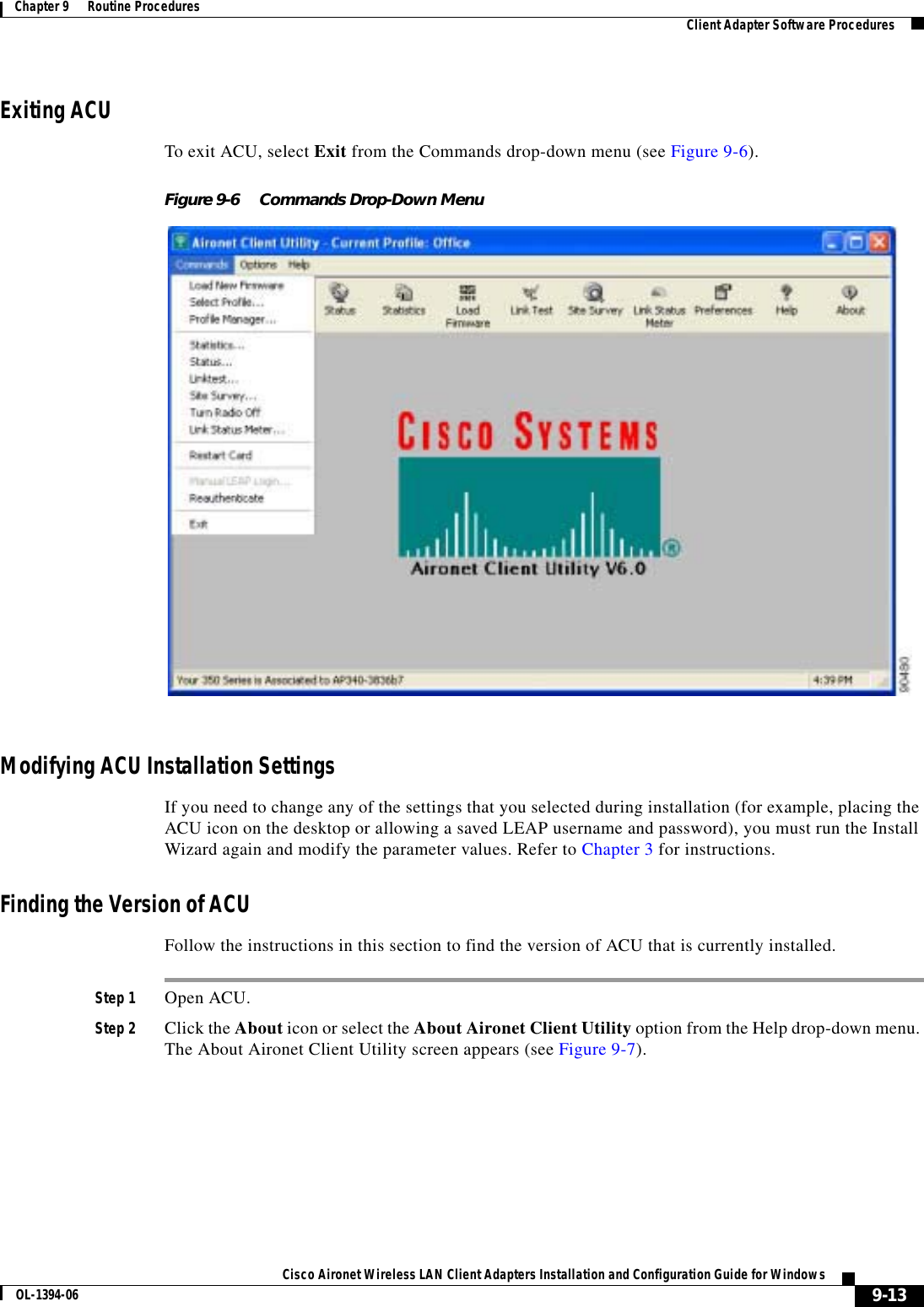
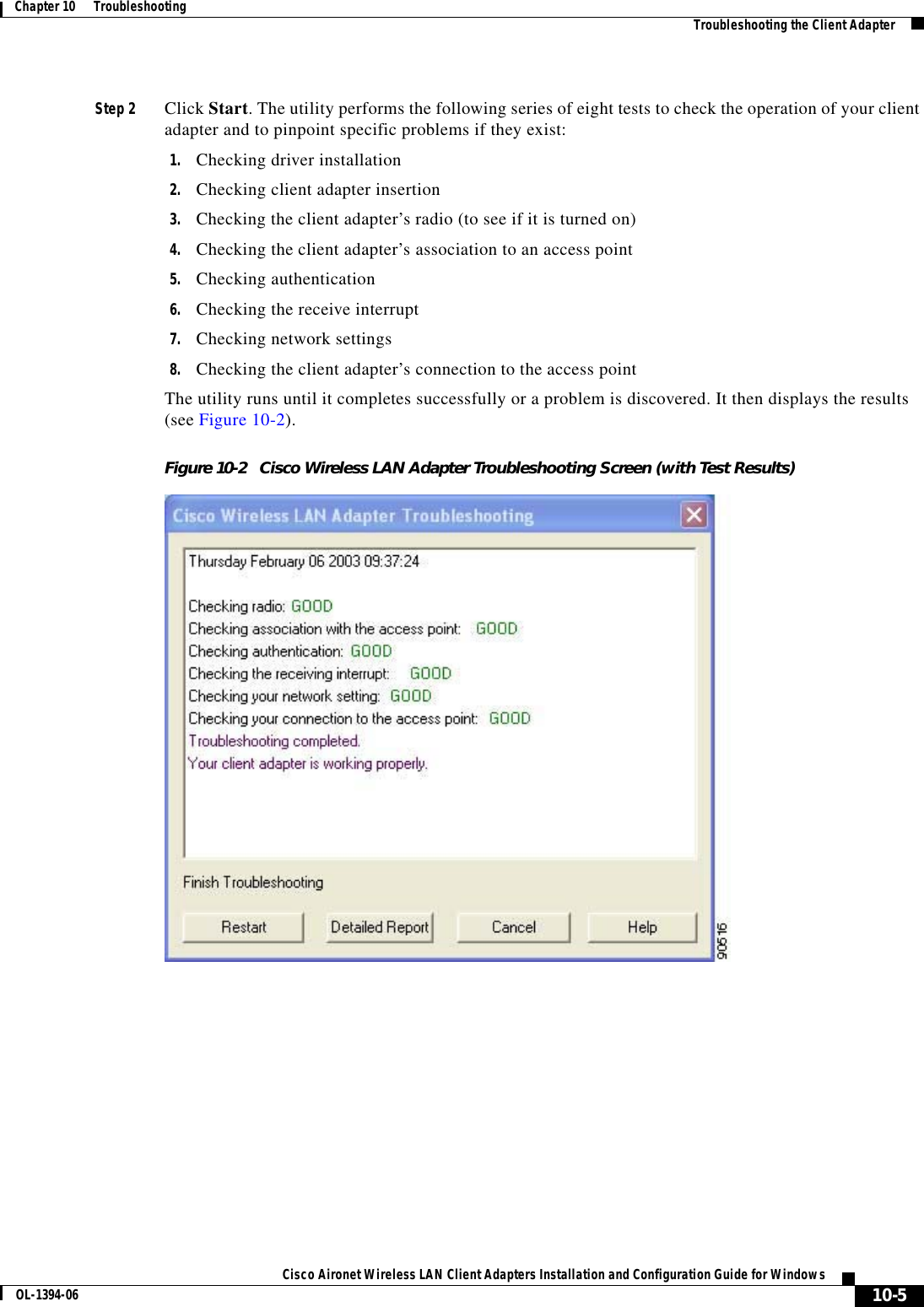
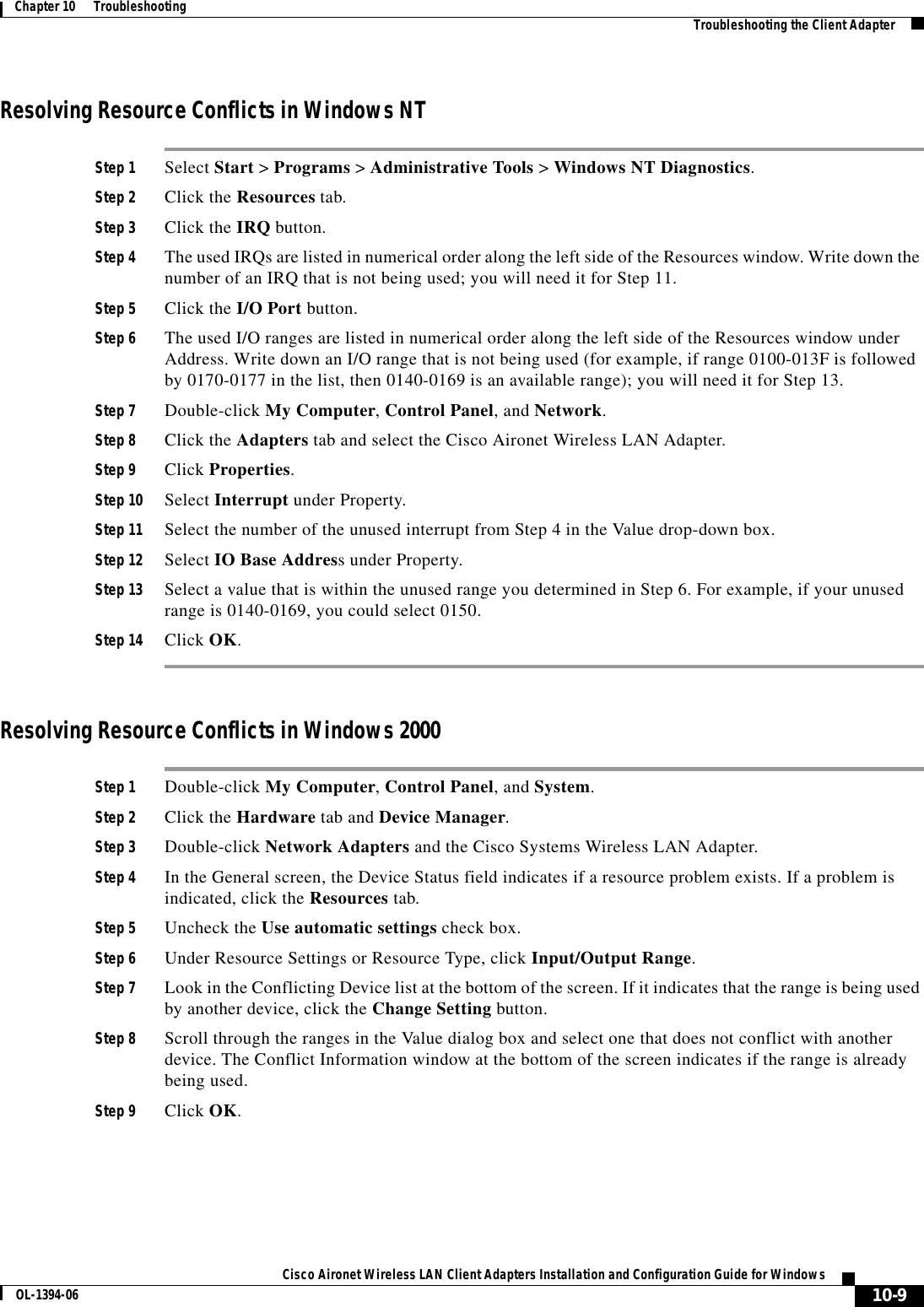
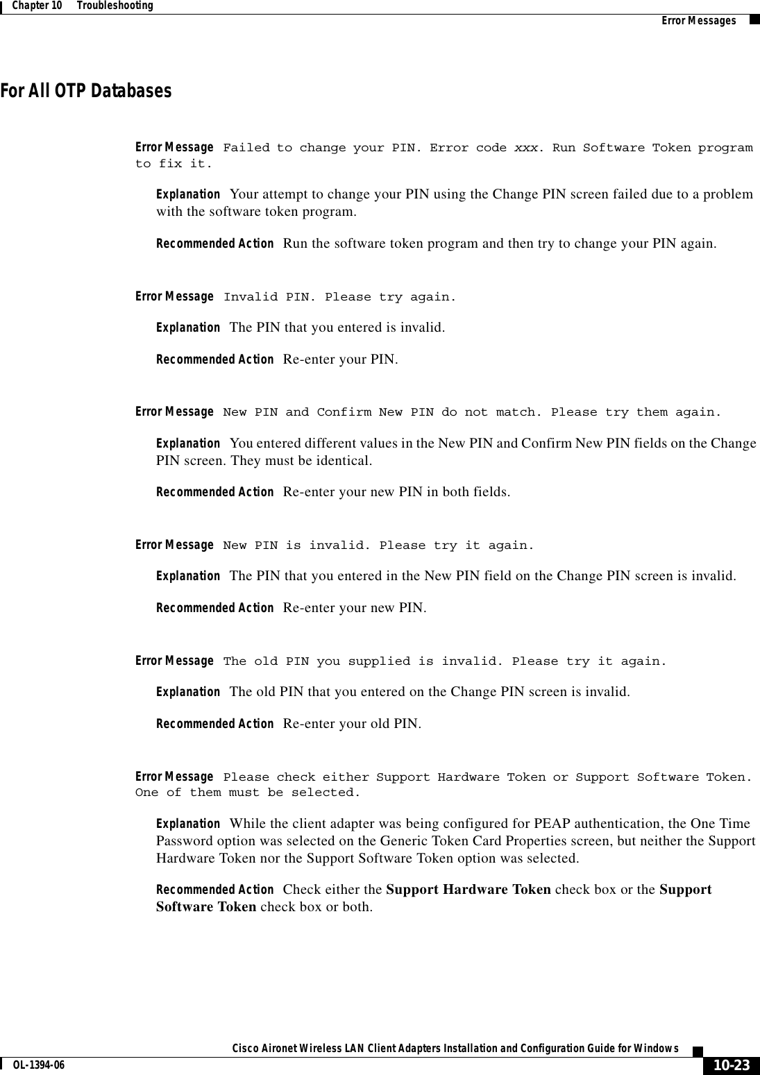
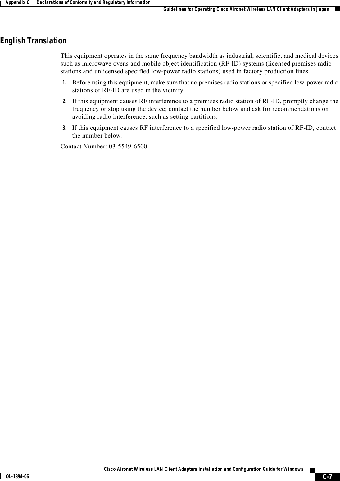
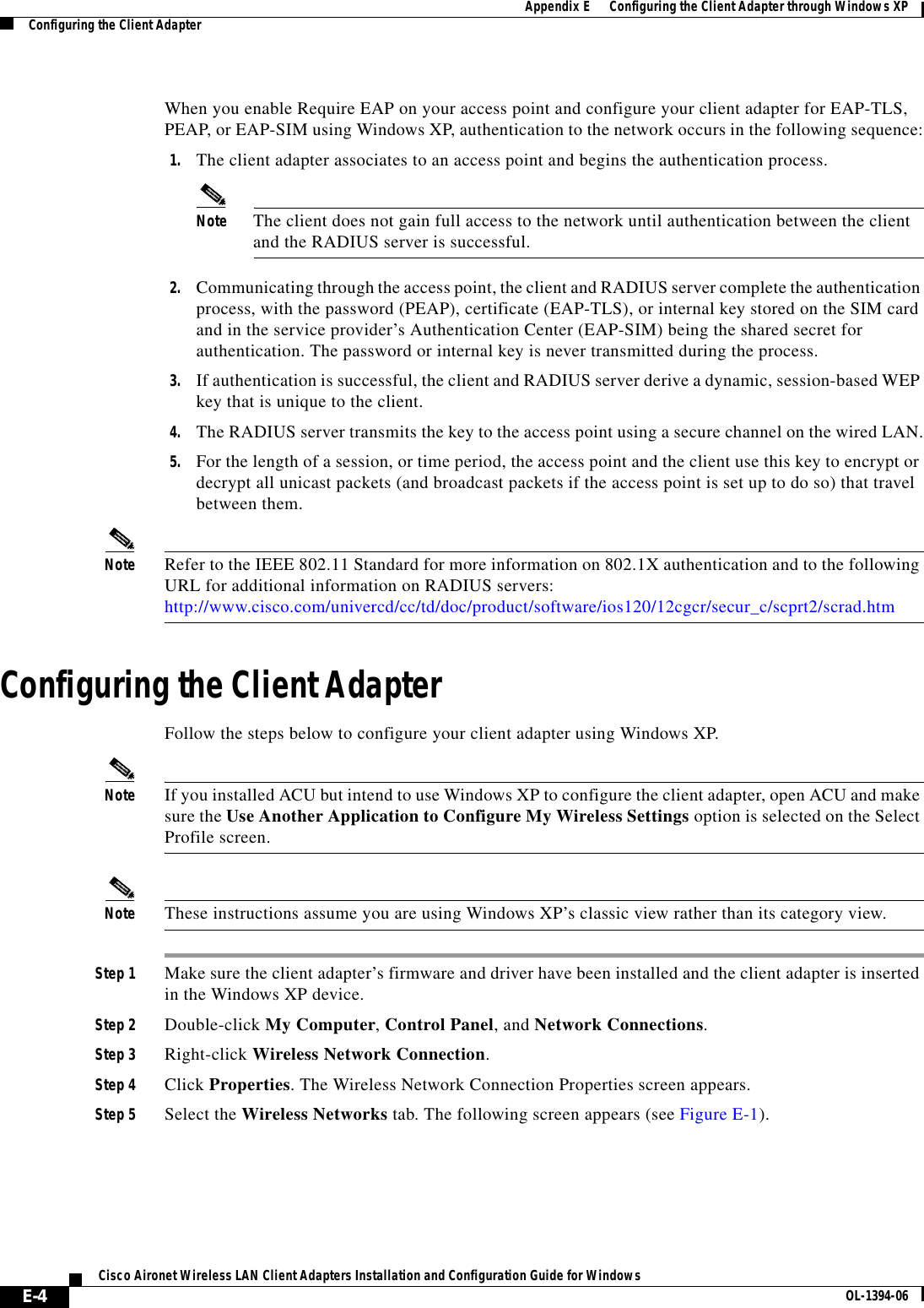
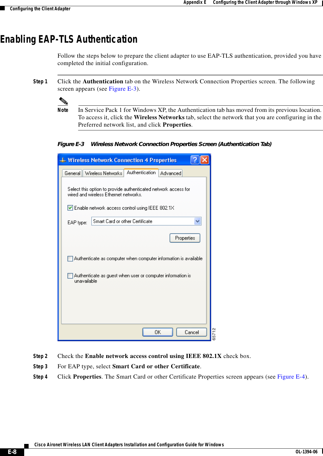
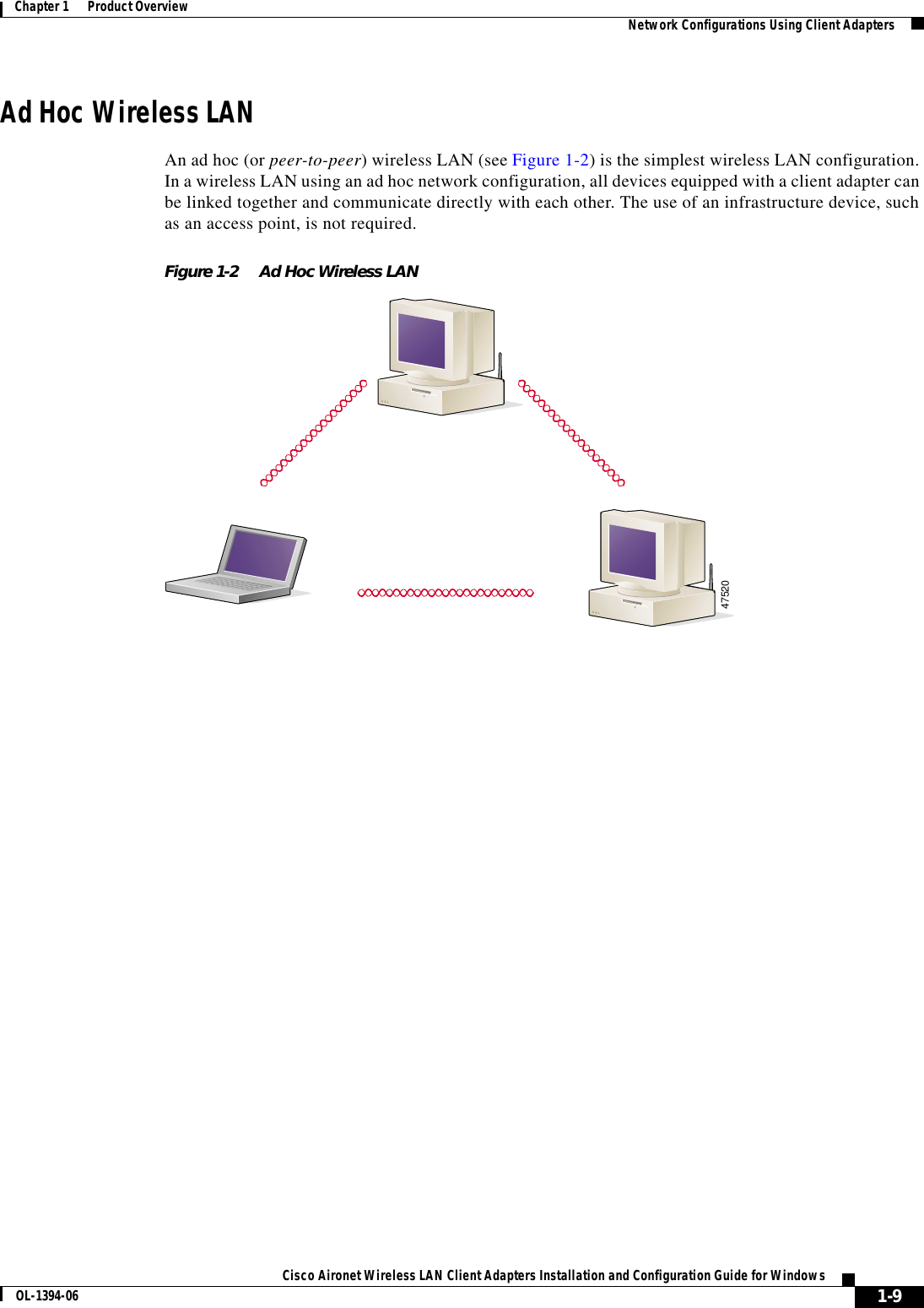
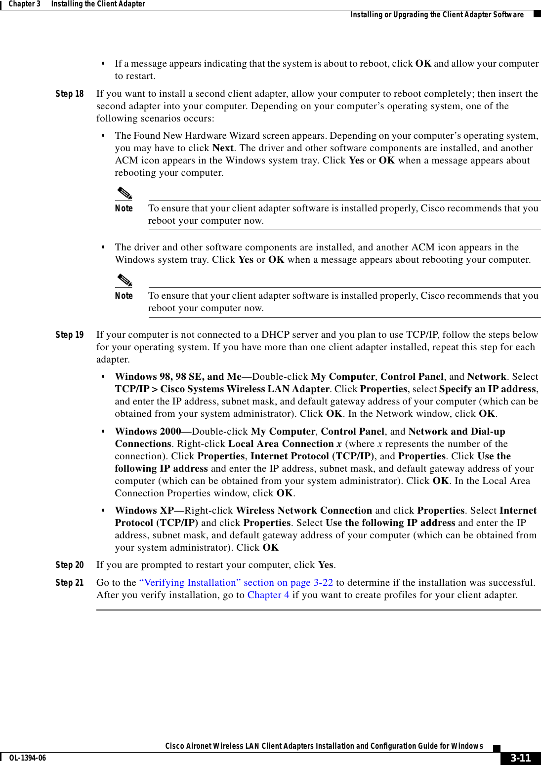
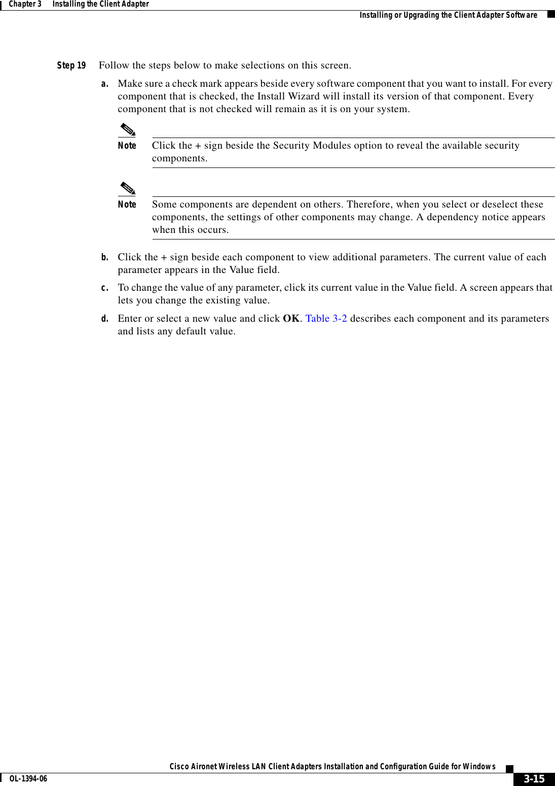
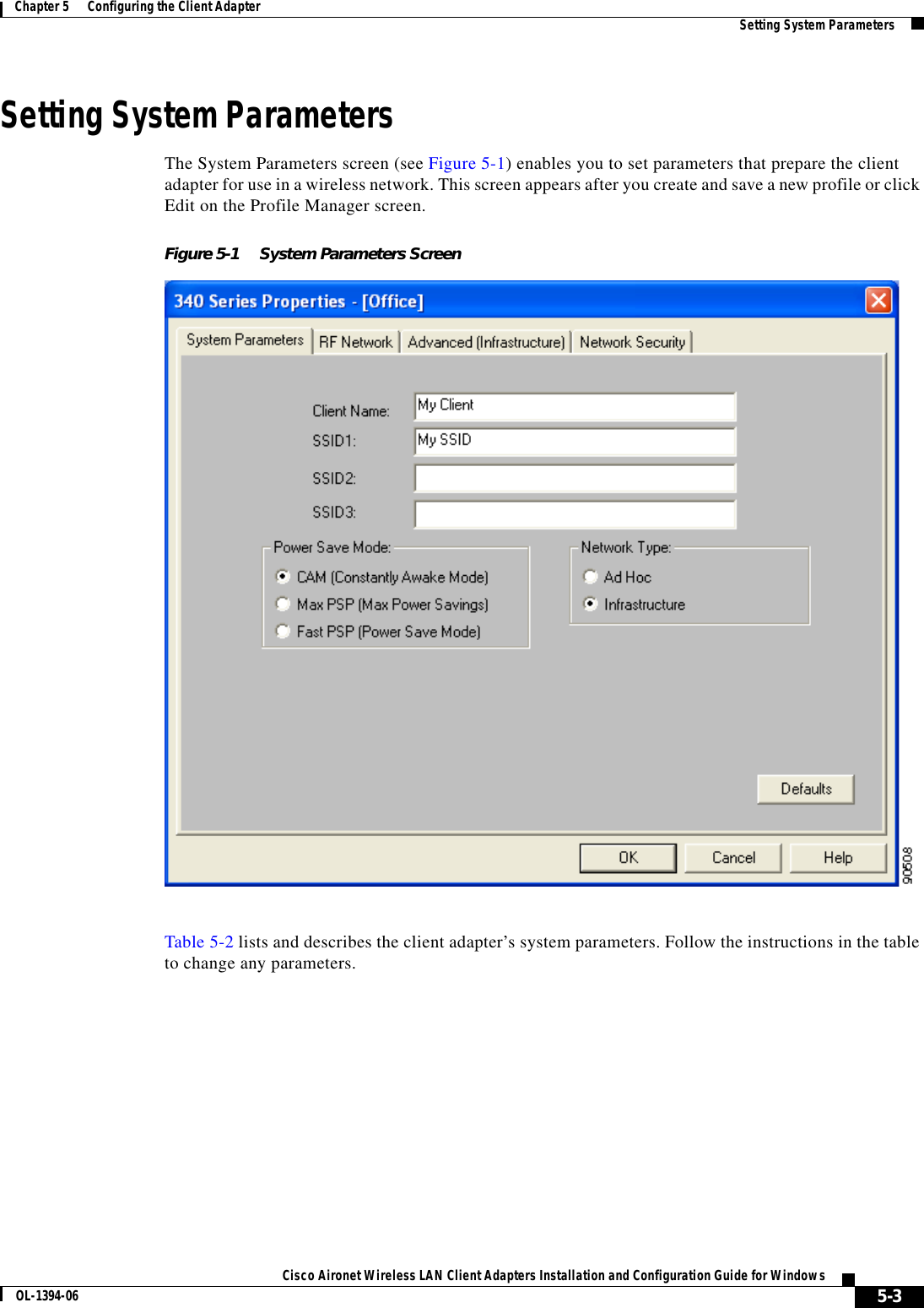
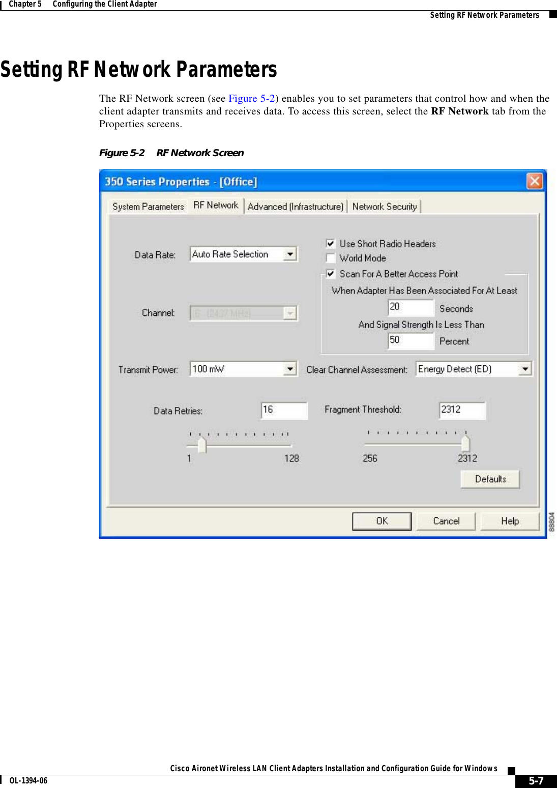
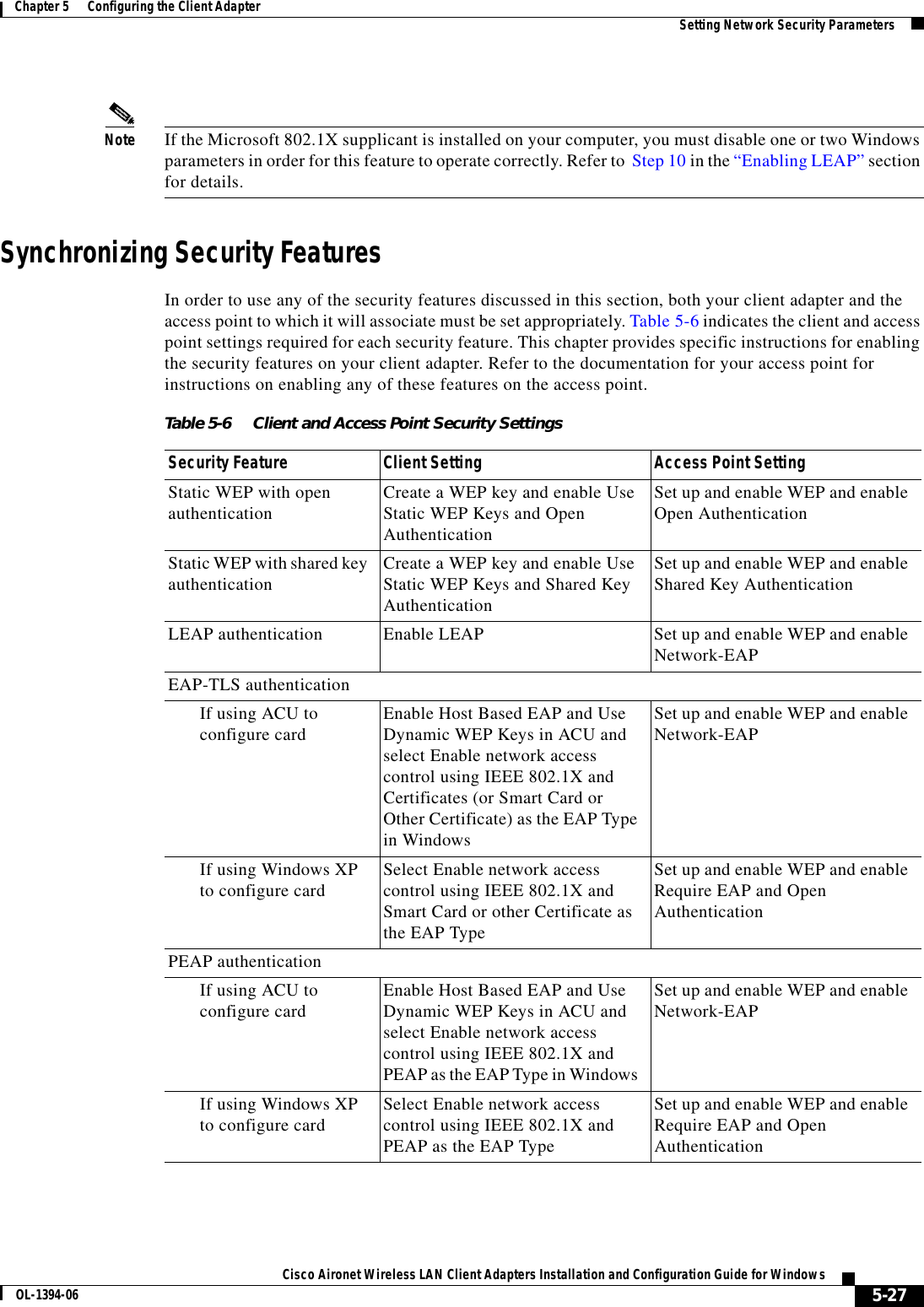
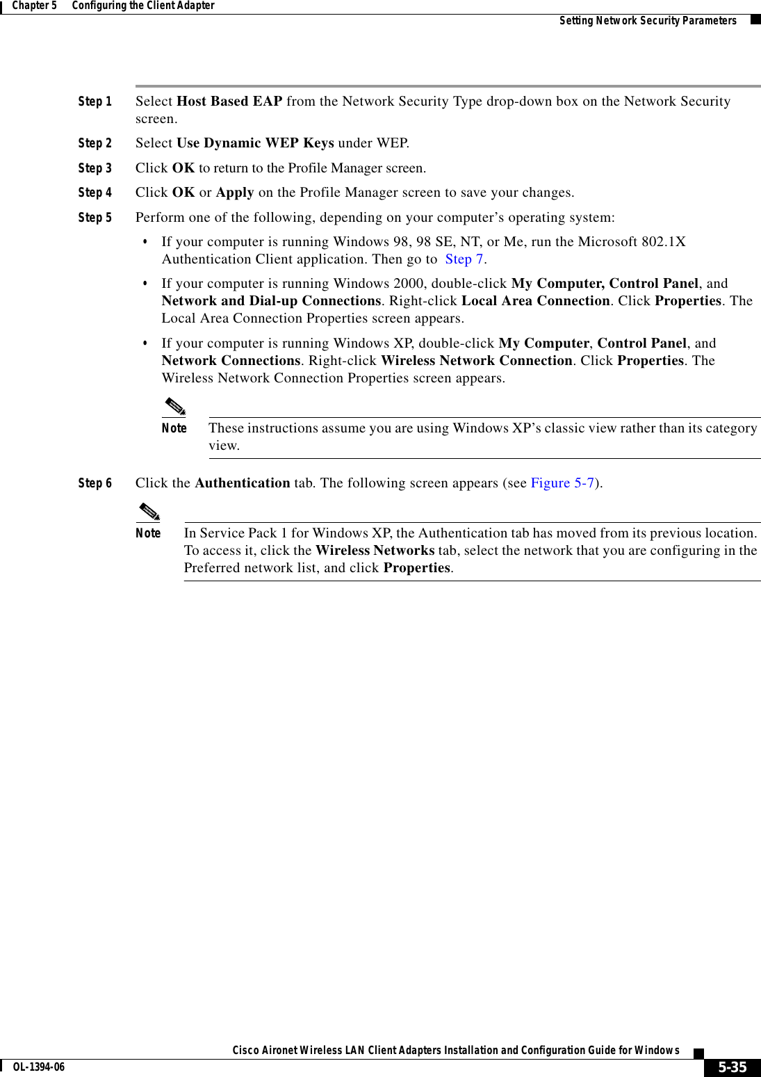
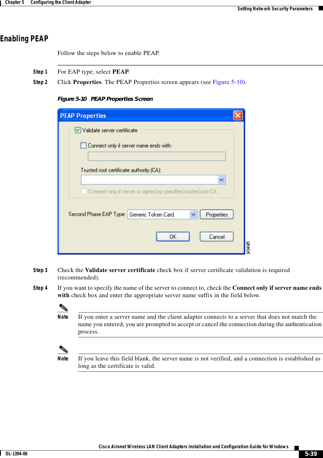
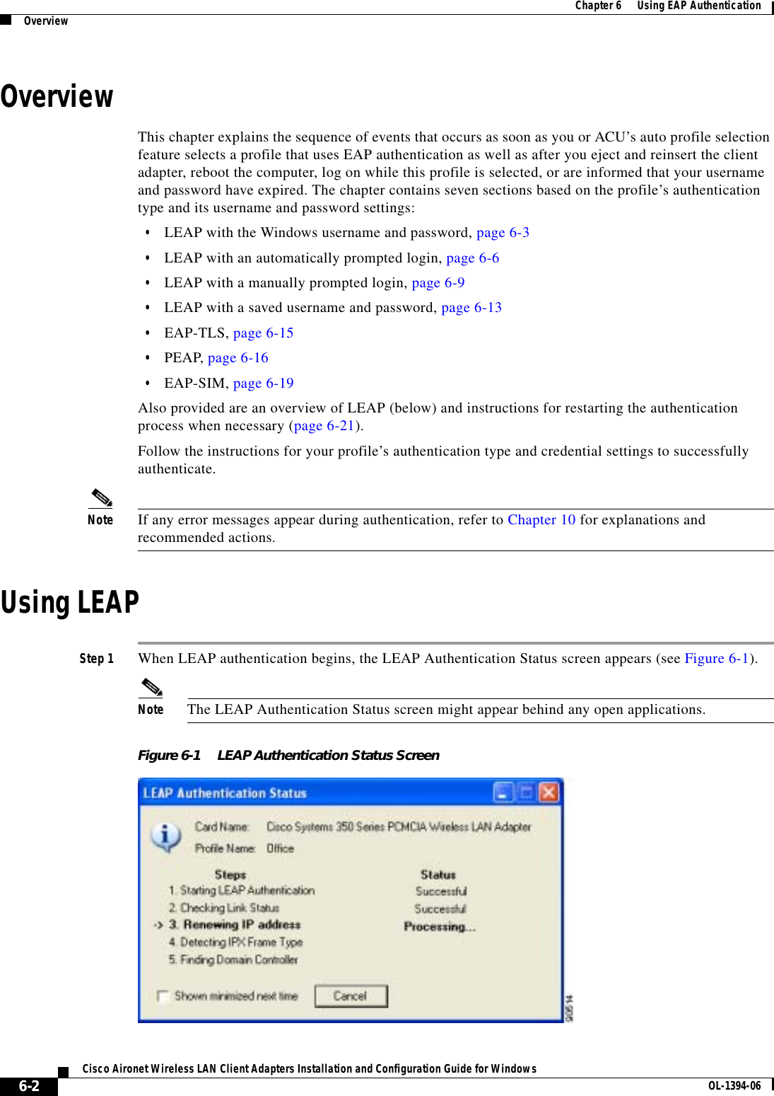
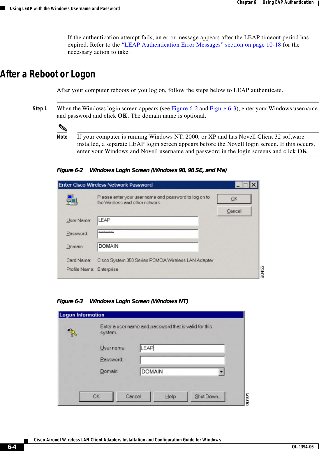
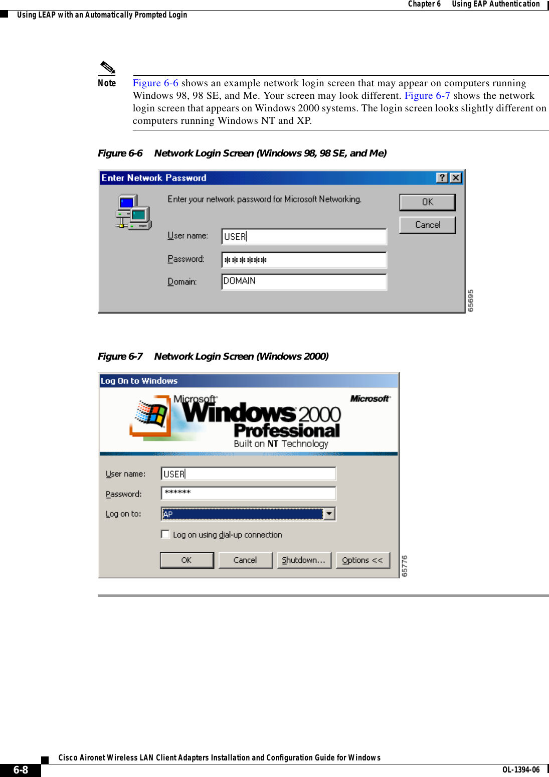
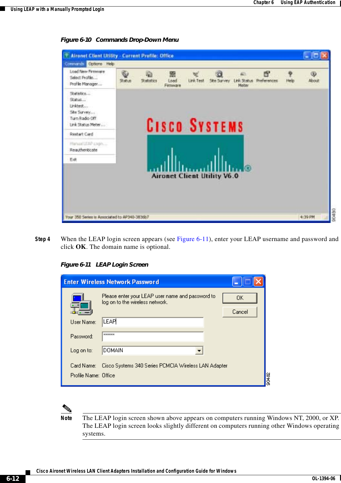
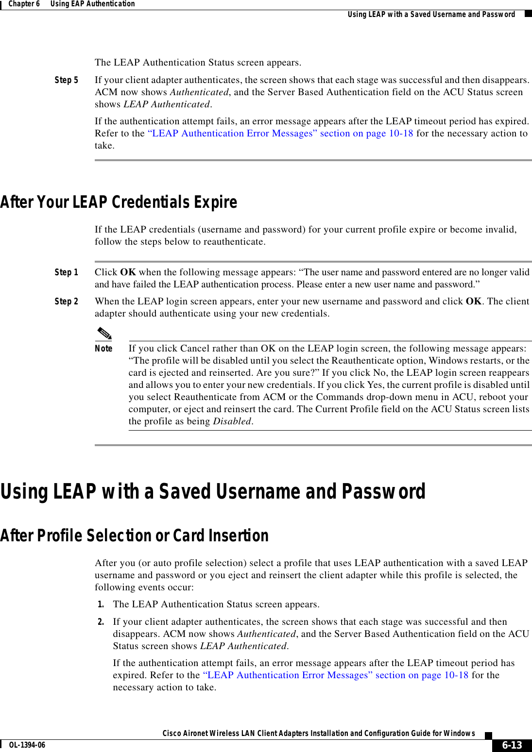
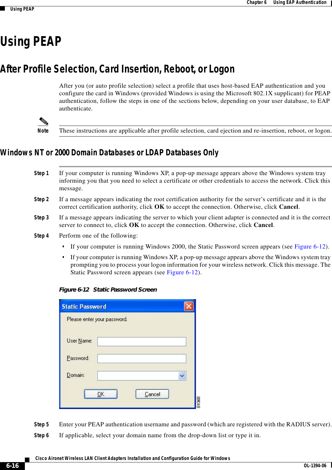
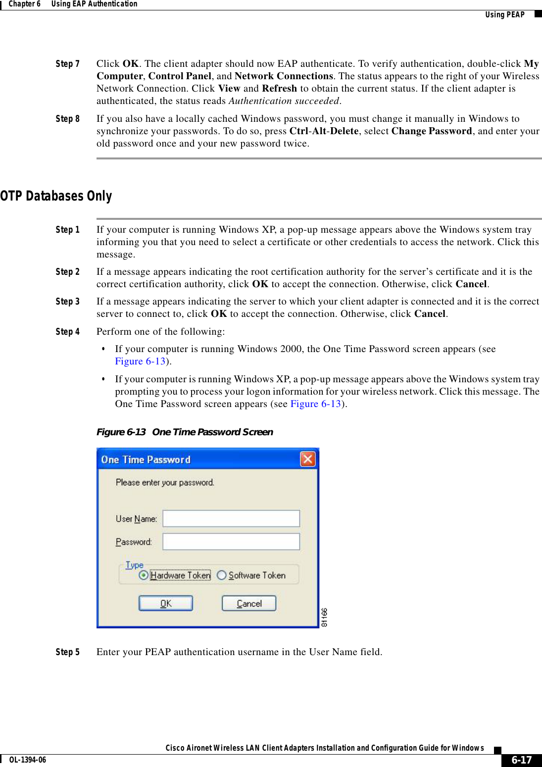
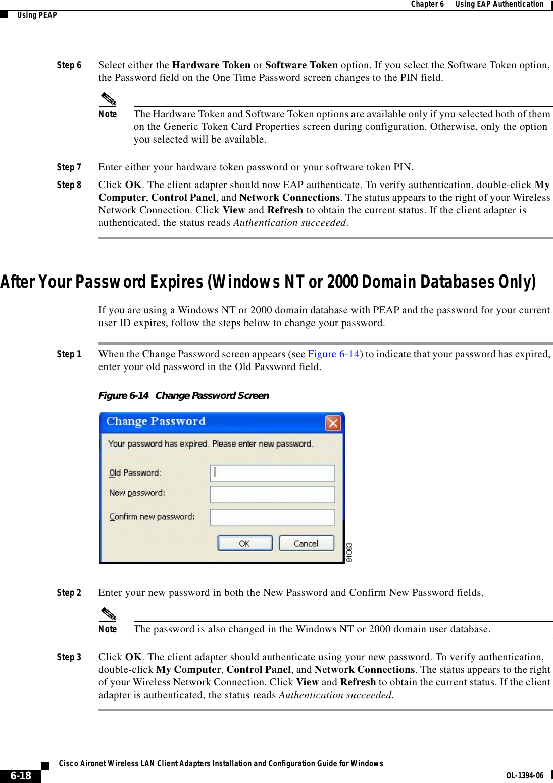
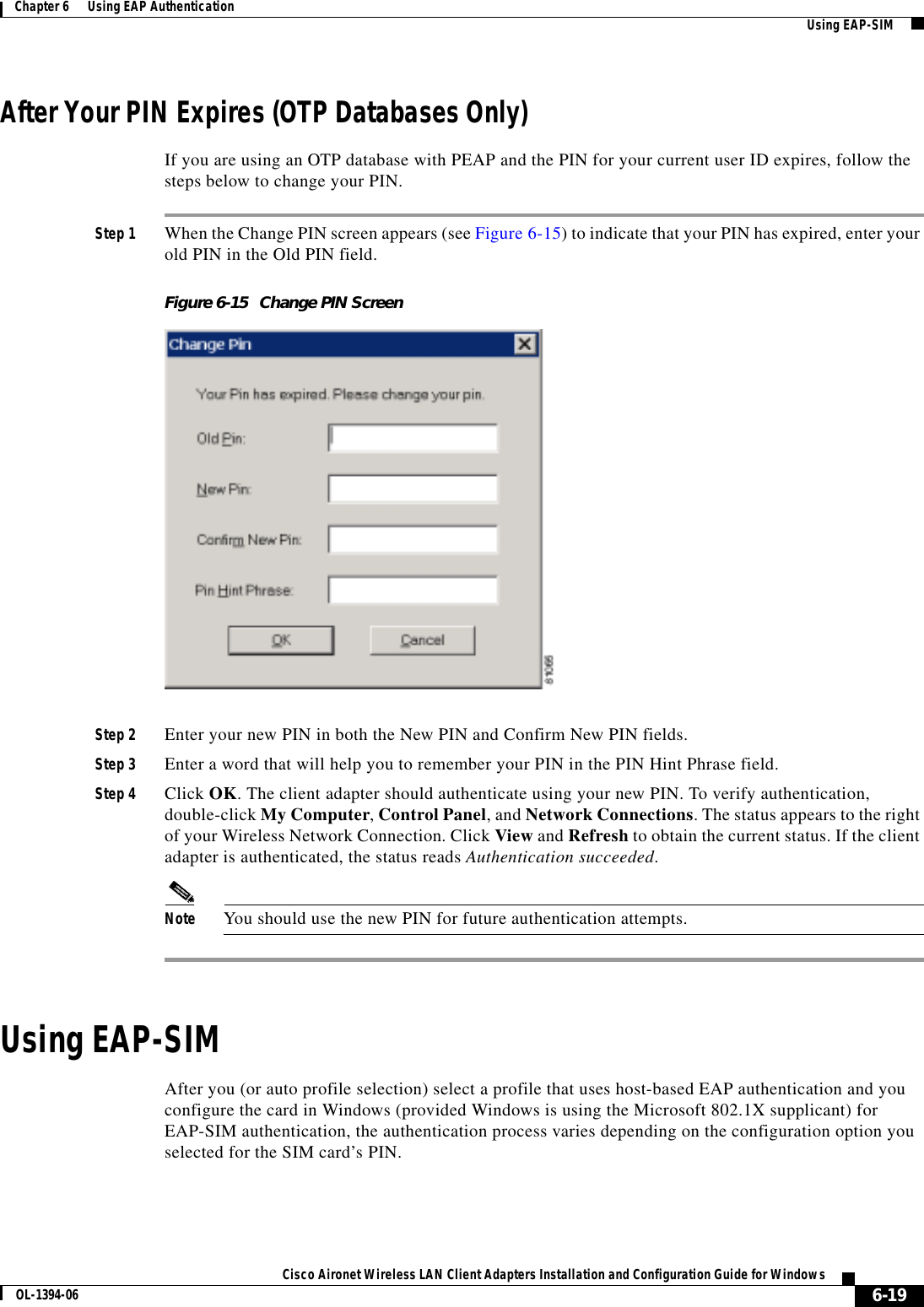
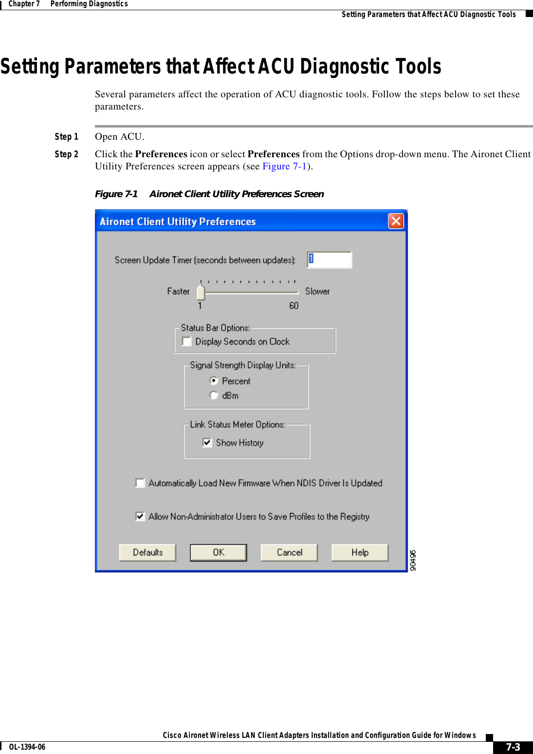
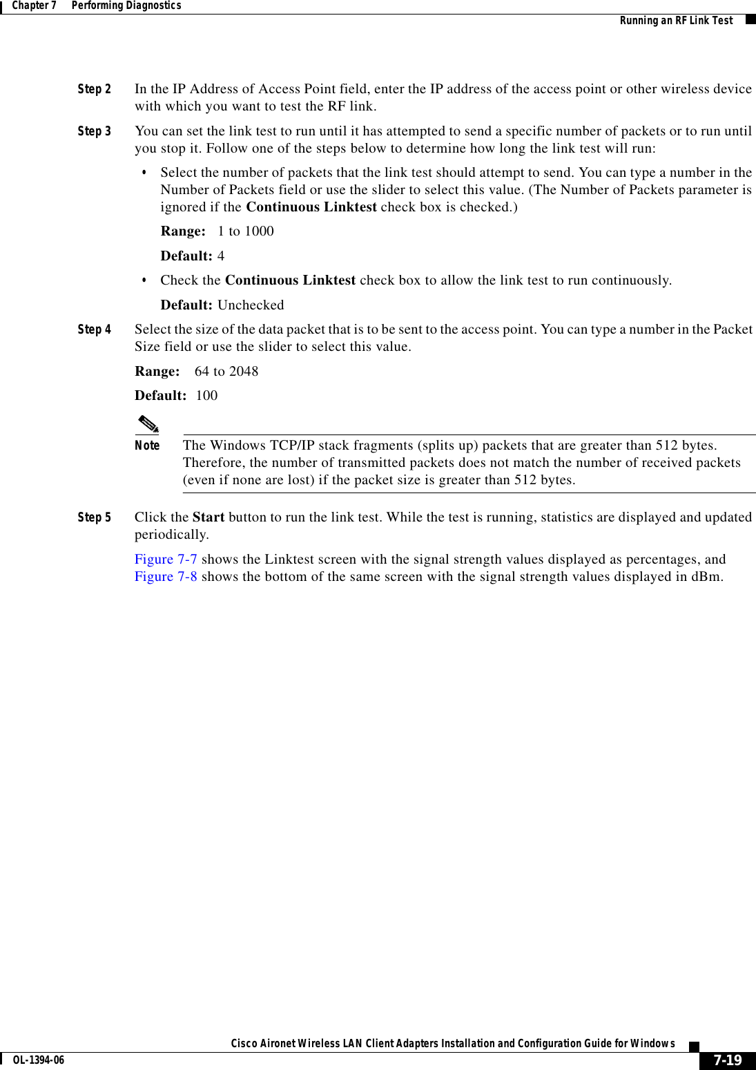
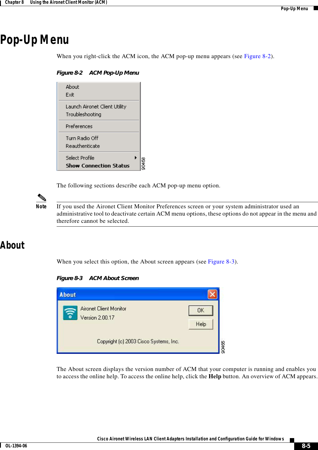
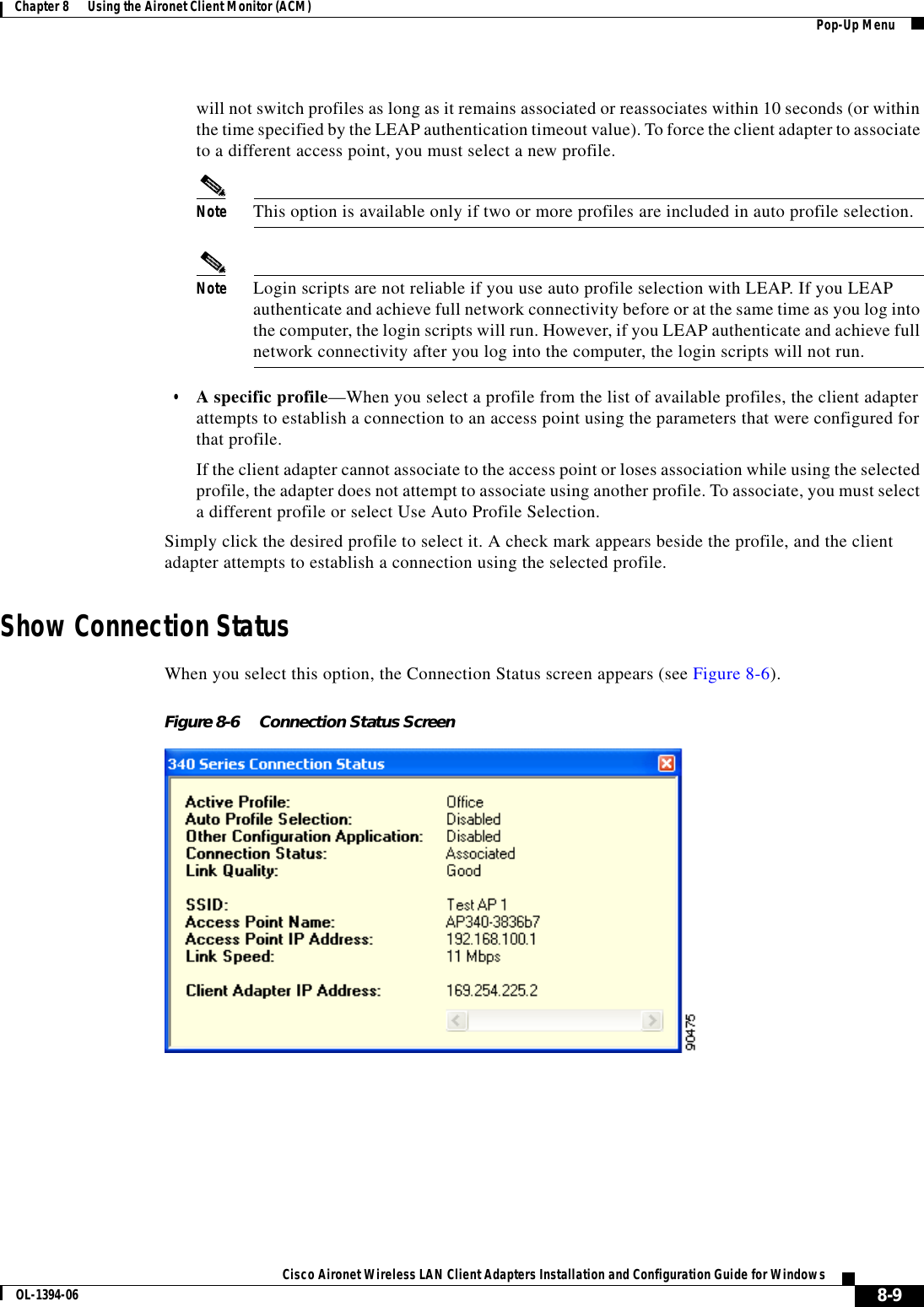
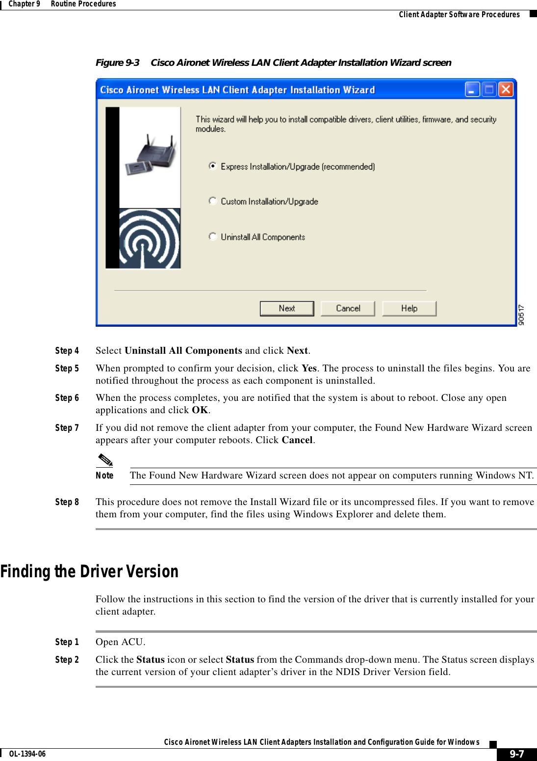
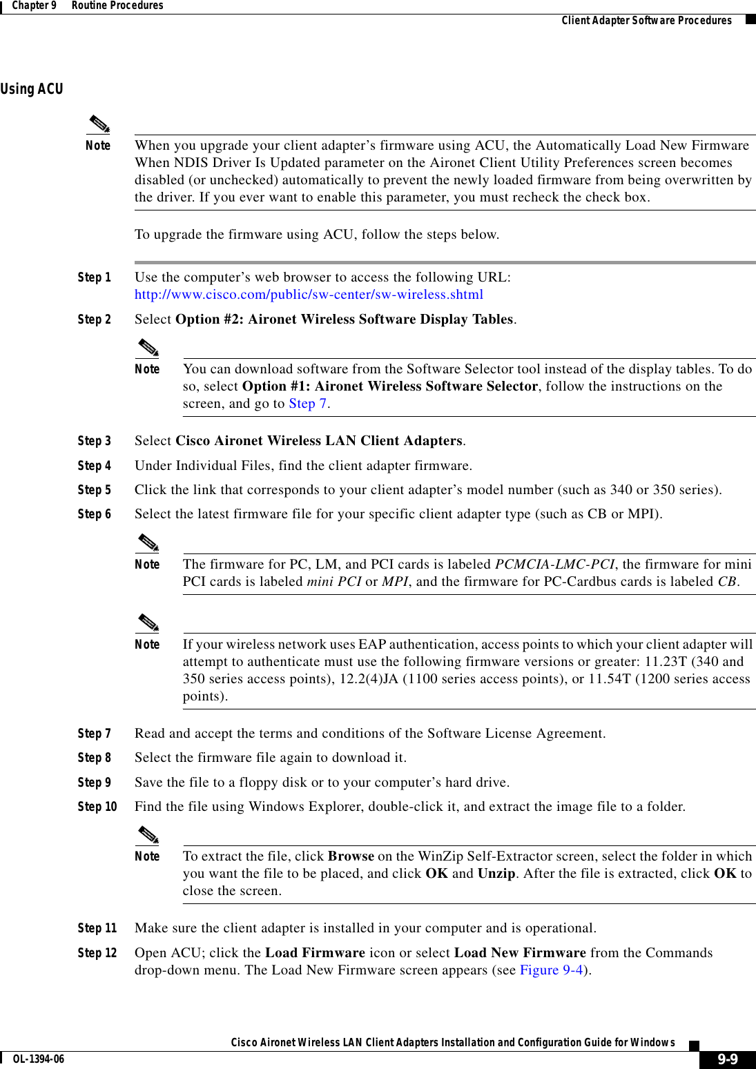
![xivCisco Aironet Wireless LAN Client Adapters Installation and Configuration Guide for Windows OL-1394-06PrefaceConventionsAttentionCe symbole d’avertissement indique un danger. Vous vous trouvez dans une situation pouvant entraîner des blessures. Avant d’accéder à cet équipement, soyez conscient des dangers posés par les circuits électriques et familiarisez-vous avec les procédures courantes de prévention des accidents. Pour obtenir les traductions des mises en garde figurant dans cette publication, veuillez consulter l’annexe intitulée « Translated Safety Warnings » (Traduction des avis de sécurité).WarnungDieses Warnsymbol bedeutet Gefahr. Sie befinden sich in einer Situation, die zu einer Körperverletzung führen könnte. Bevor Sie mit der Arbeit an irgendeinem Gerät beginnen, seien Sie sich der mit elektrischen Stromkreisen verbundenen Gefahren und der Standardpraktiken zur Vermeidung von Unfällen bewußt. (Übersetzungen der in dieser Veröffentlichung enthaltenen Warnhinweise finden Sie im Anhang mit dem Titel “Translated Safety Warnings” (Übersetzung der Warnhinweise).)AvvertenzaQuesto simbolo di avvertenza indica un pericolo. Si è in una situazione che può causare infortuni. Prima di lavorare su qualsiasi apparecchiatura, occorre conoscere i pericoli relativi ai circuiti elettrici ed essere al corrente delle pratiche standard per la prevenzione di incidenti. La traduzione delle avvertenze riportate in questa pubblicazione si trova nell’appendice, “Translated Safety Warnings” (Traduzione delle avvertenze di sicurezza).AdvarselDette varselsymbolet betyr fare. Du befinner deg i en situasjon som kan føre til personskade. Før du utfører arbeid på utstyr, må du være oppmerksom på de faremomentene som elektriske kretser innebærer, samt gjøre deg kjent med vanlig praksis når det gjelder å unngå ulykker. (Hvis du vil se oversettelser av de advarslene som finnes i denne publikasjonen, kan du se i vedlegget "Translated Safety Warnings" [Oversatte sikkerhetsadvarsler].)AvisoEste símbolo de aviso indica perigo. Encontra-se numa situação que lhe poderá causar danos fisicos. Antes de começar a trabalhar com qualquer equipamento, familiarize-se com os perigos relacionados com circuitos eléctricos, e com quaisquer práticas comuns que possam prevenir possíveis acidentes. (Para ver as traduções dos avisos que constam desta publicação, consulte o apêndice “Translated Safety Warnings” - “Traduções dos Avisos de Segurança”).¡Advertencia!Este símbolo de aviso significa peligro. Existe riesgo para su integridad física. Antes de manipular cualquier equipo, considerar los riesgos que entraña la corriente eléctrica y familiarizarse con los procedimientos estándar de prevención de accidentes. (Para ver traducciones de las advertencias que aparecen en esta publicación, consultar el apéndice titulado “Translated Safety Warnings.”)Varning!Denna varningssymbol signalerar fara. Du befinner dig i en situation som kan leda till personskada. Innan du utför arbete på någon utrustning måste du vara medveten om farorna med elkretsar och känna till vanligt förfarande för att förebygga skador. (Se förklaringar av de varningar som förekommer i denna publikation i appendix "Translated Safety Warnings" [Översatta säkerhetsvarningar].)](https://usermanual.wiki/Xplore-Technologies/IX104-112.WLAN-Manual/User-Guide-342985-Page-14.png)


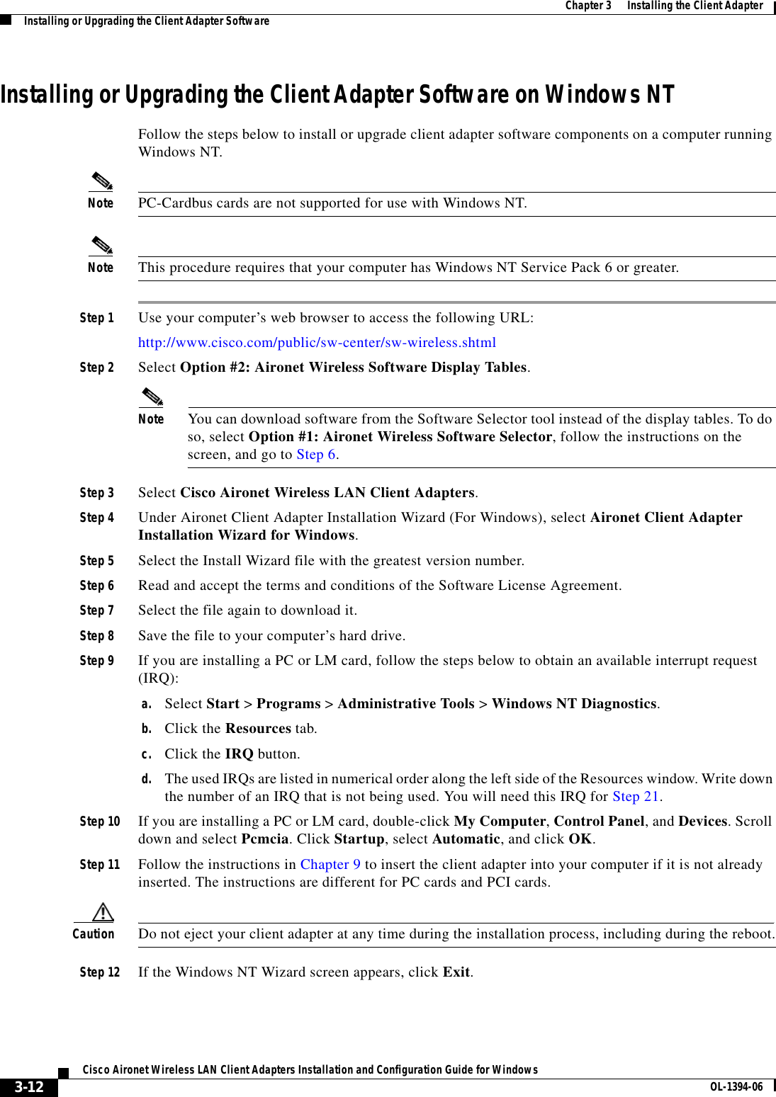
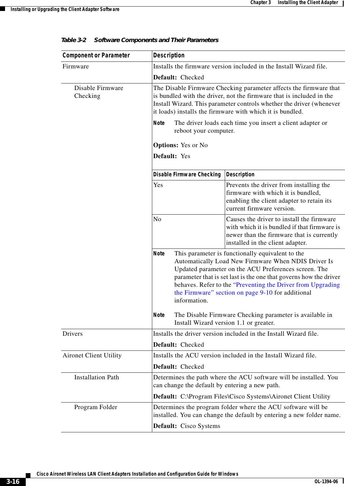
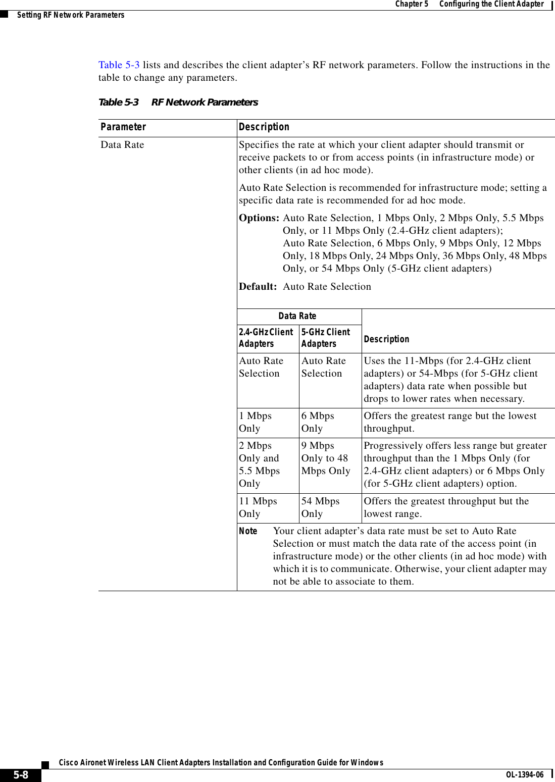
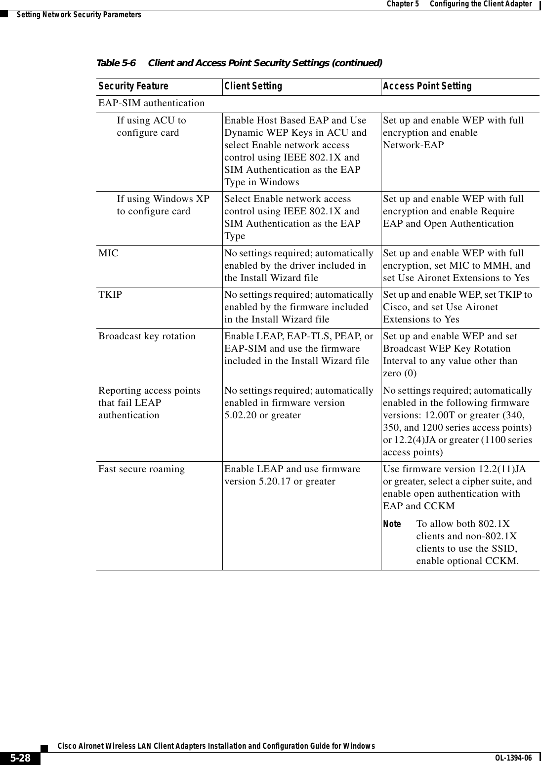
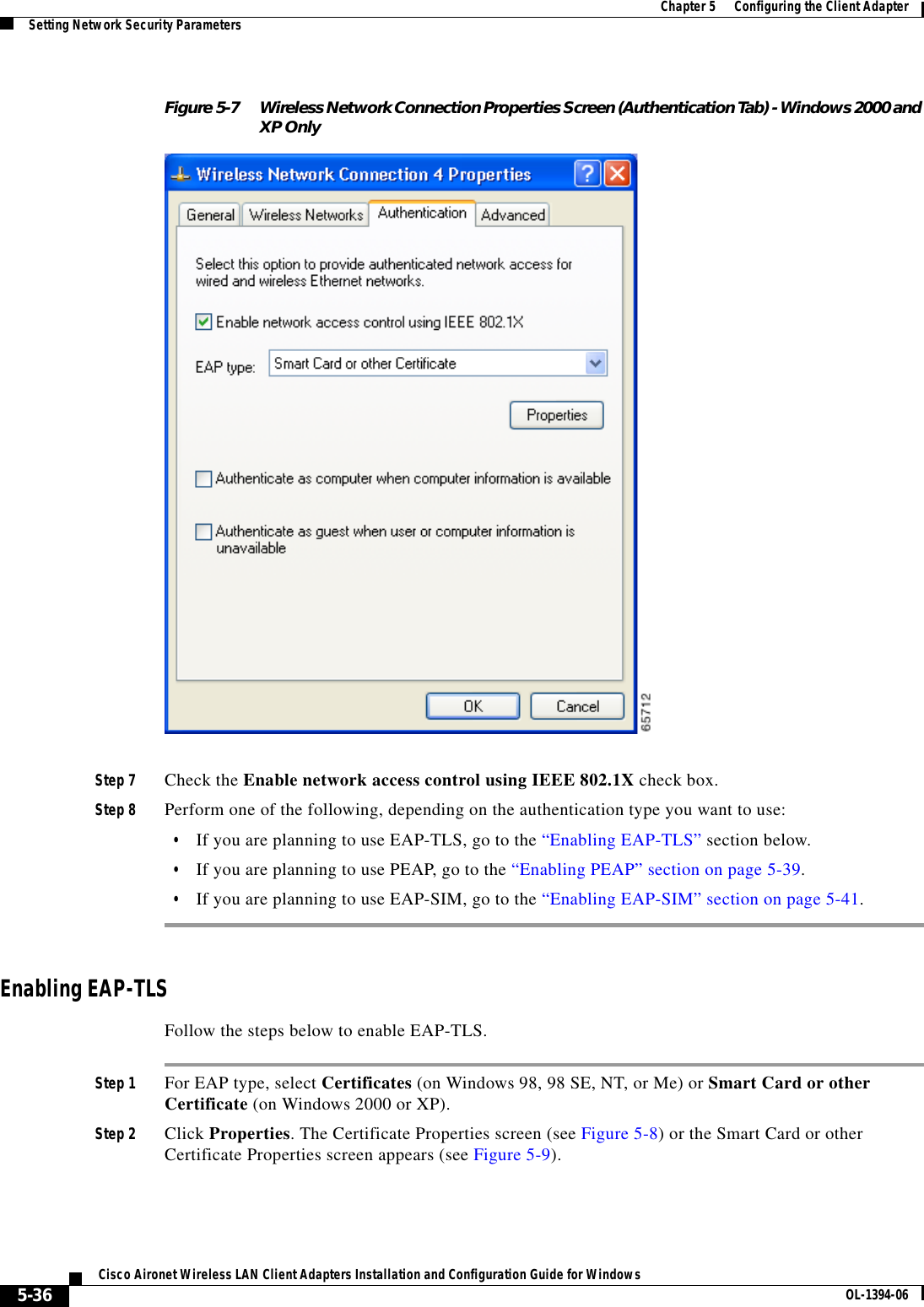
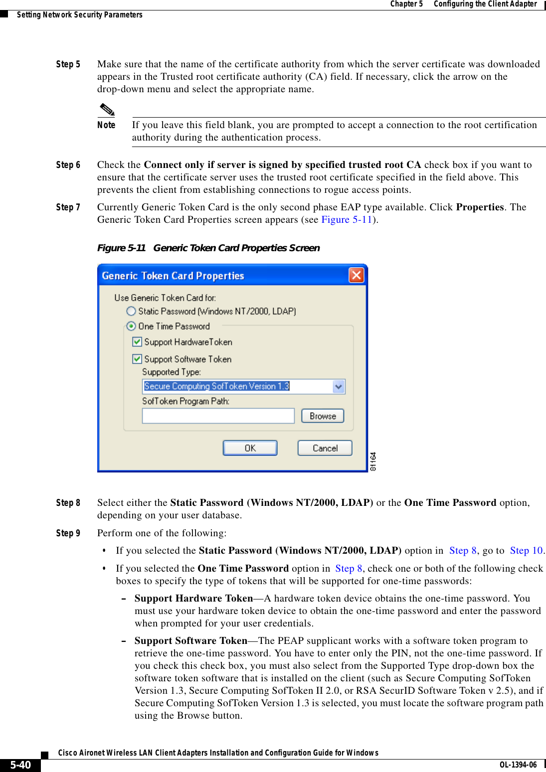

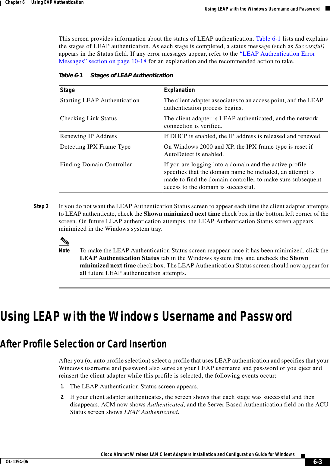
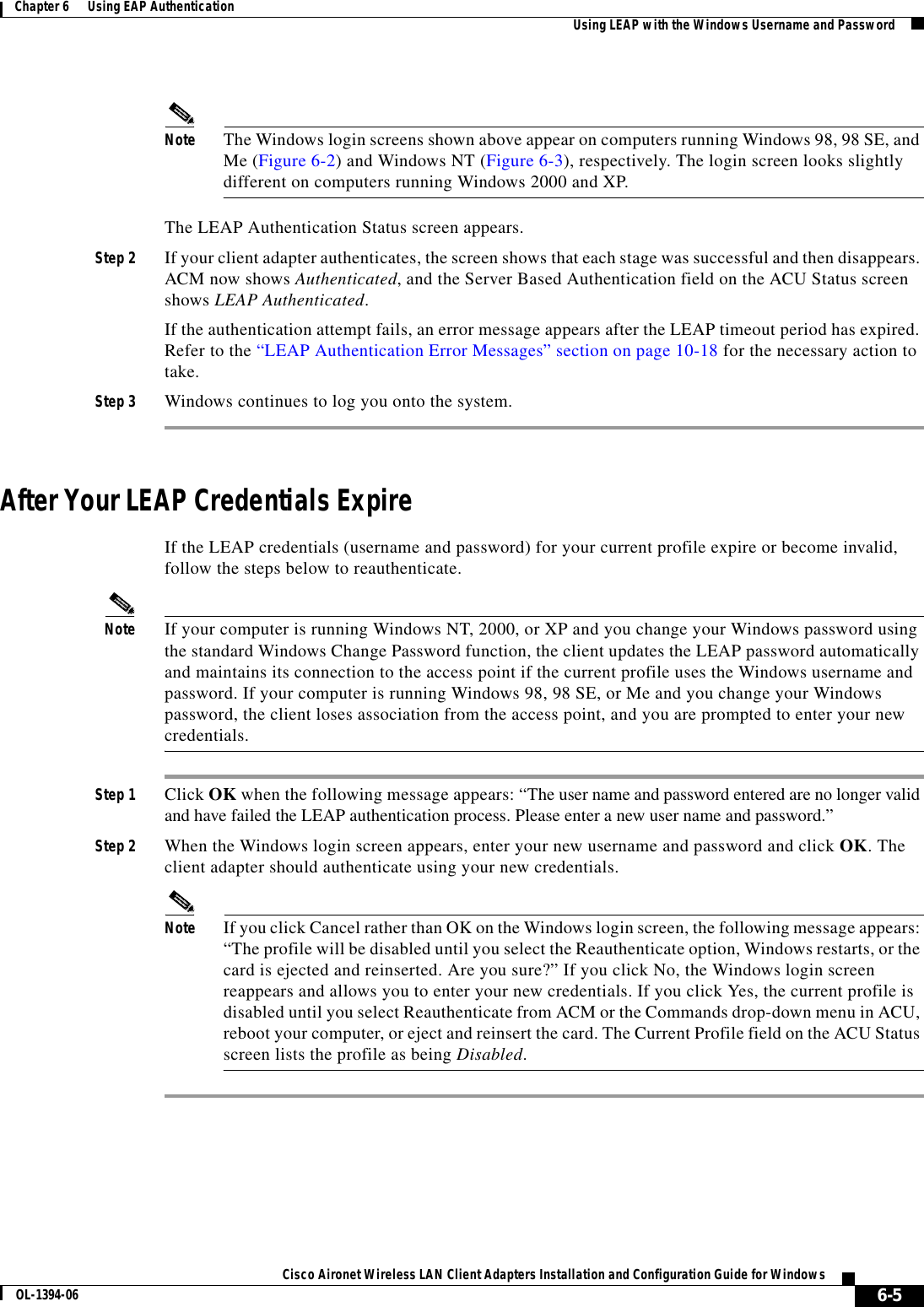
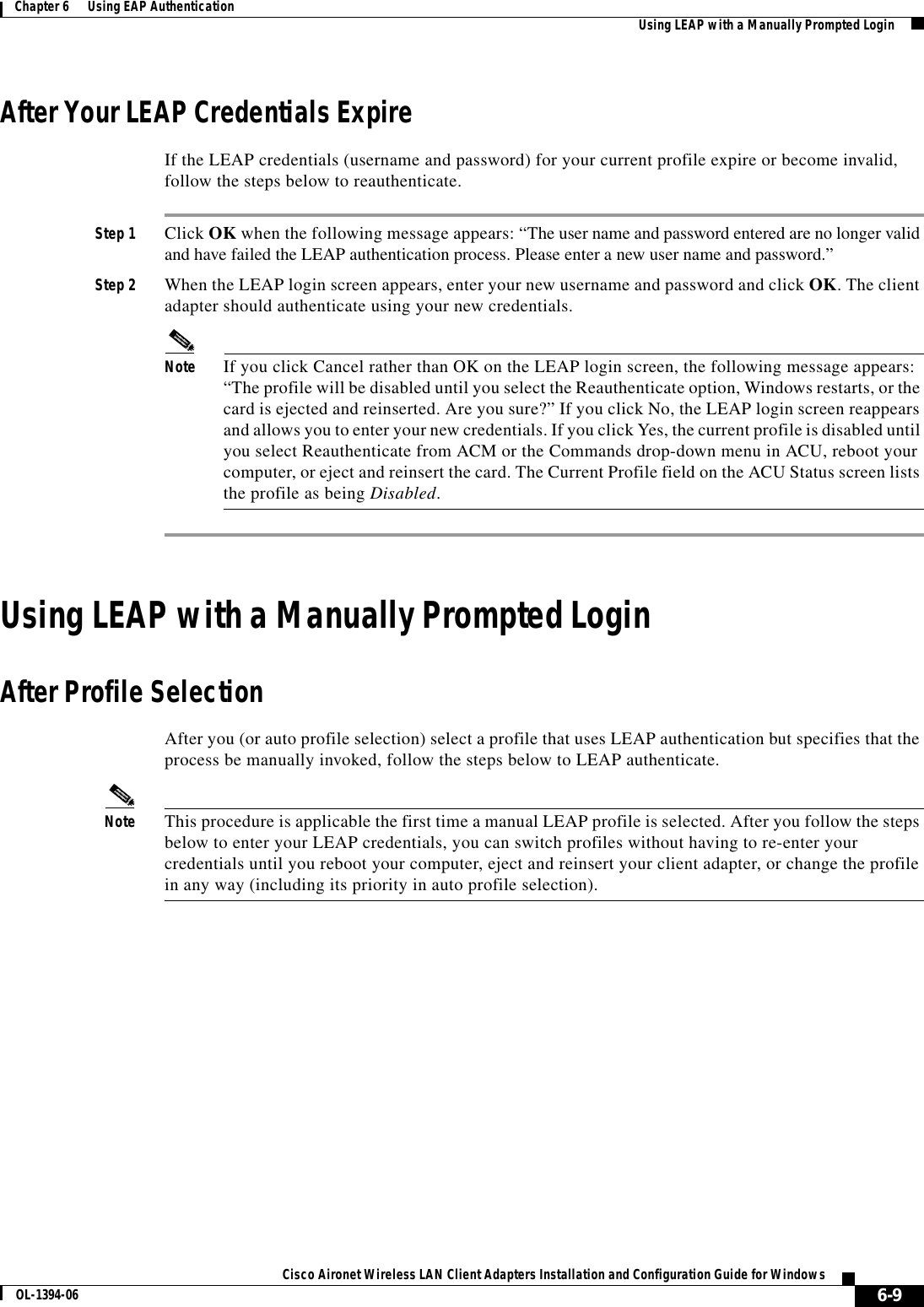

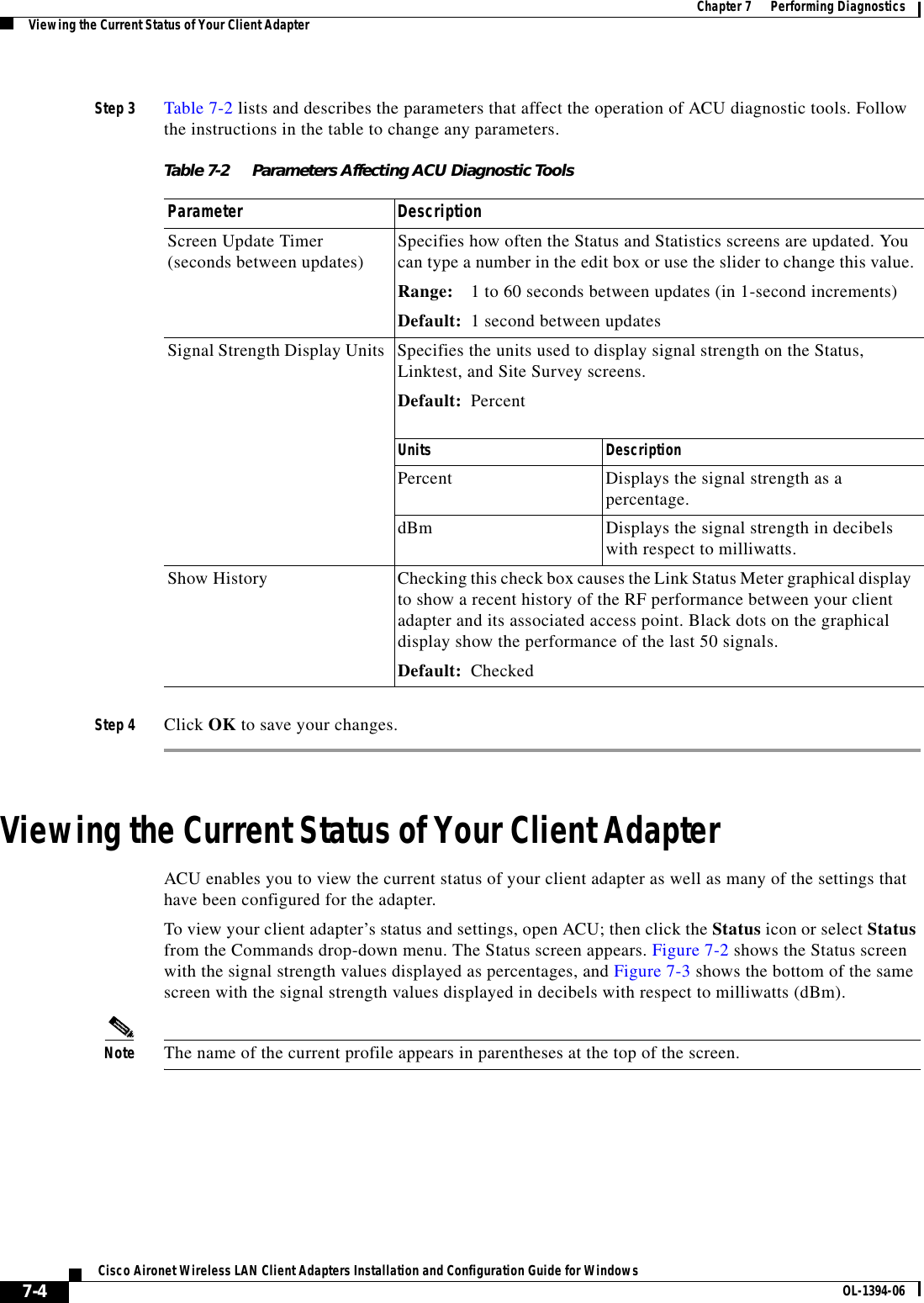
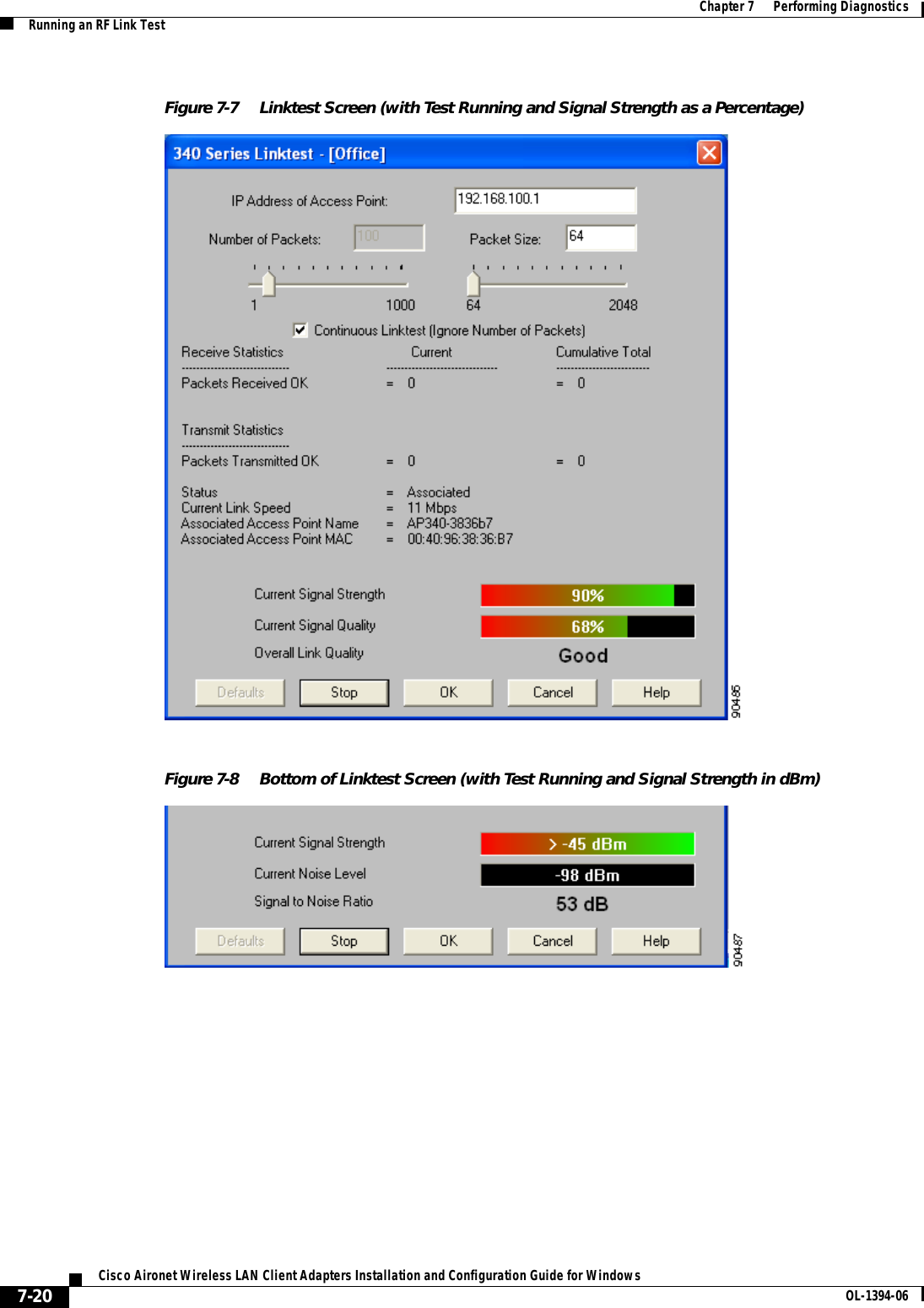
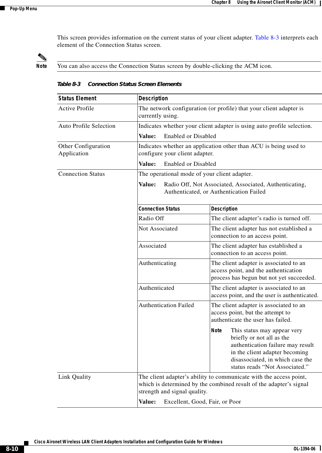
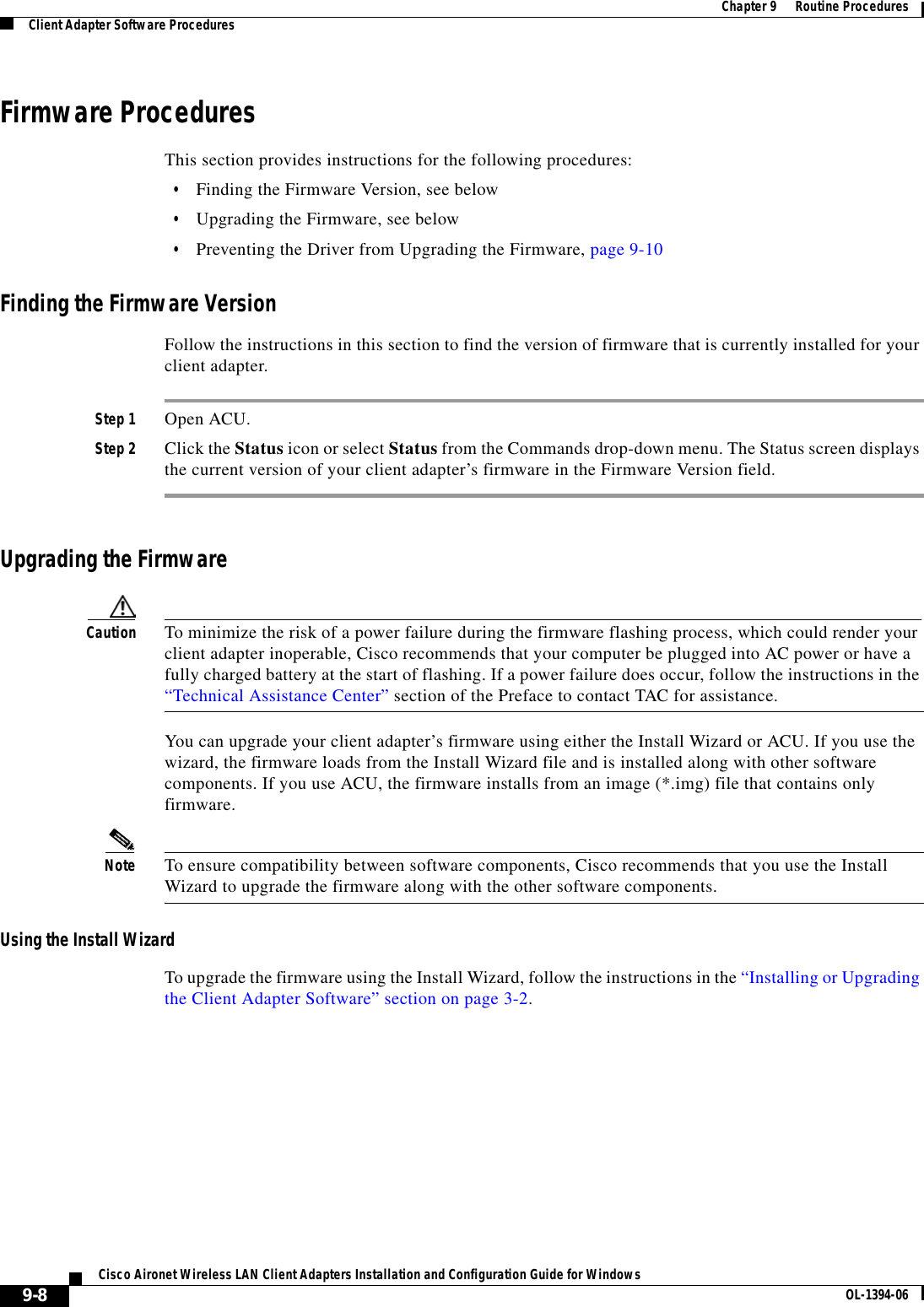
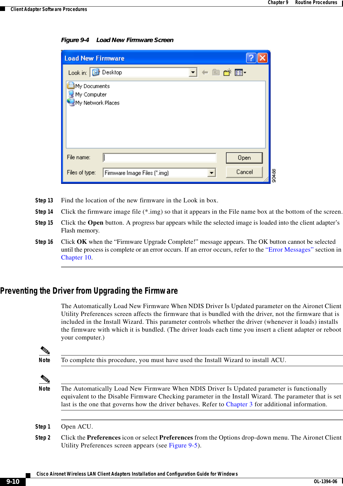
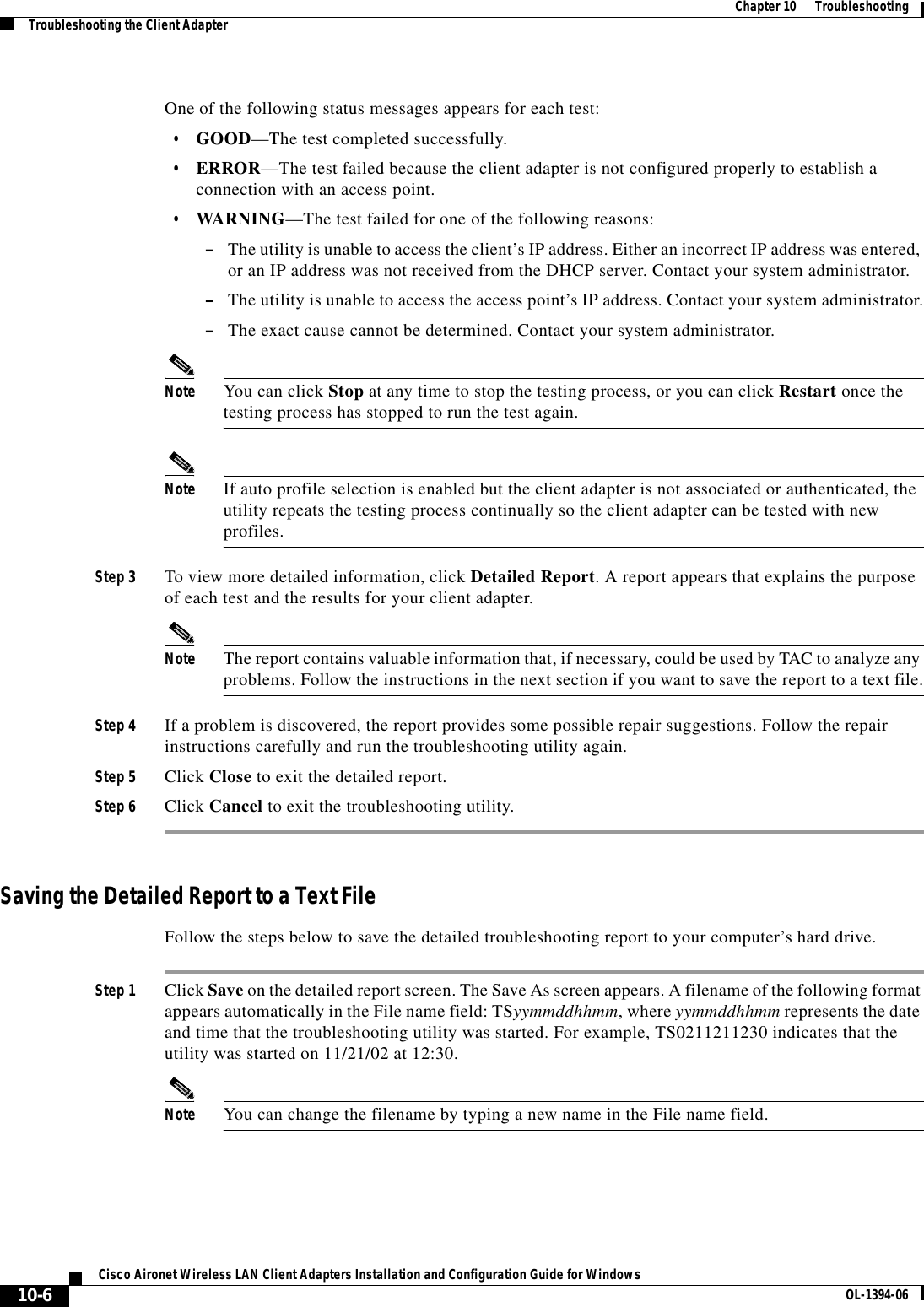
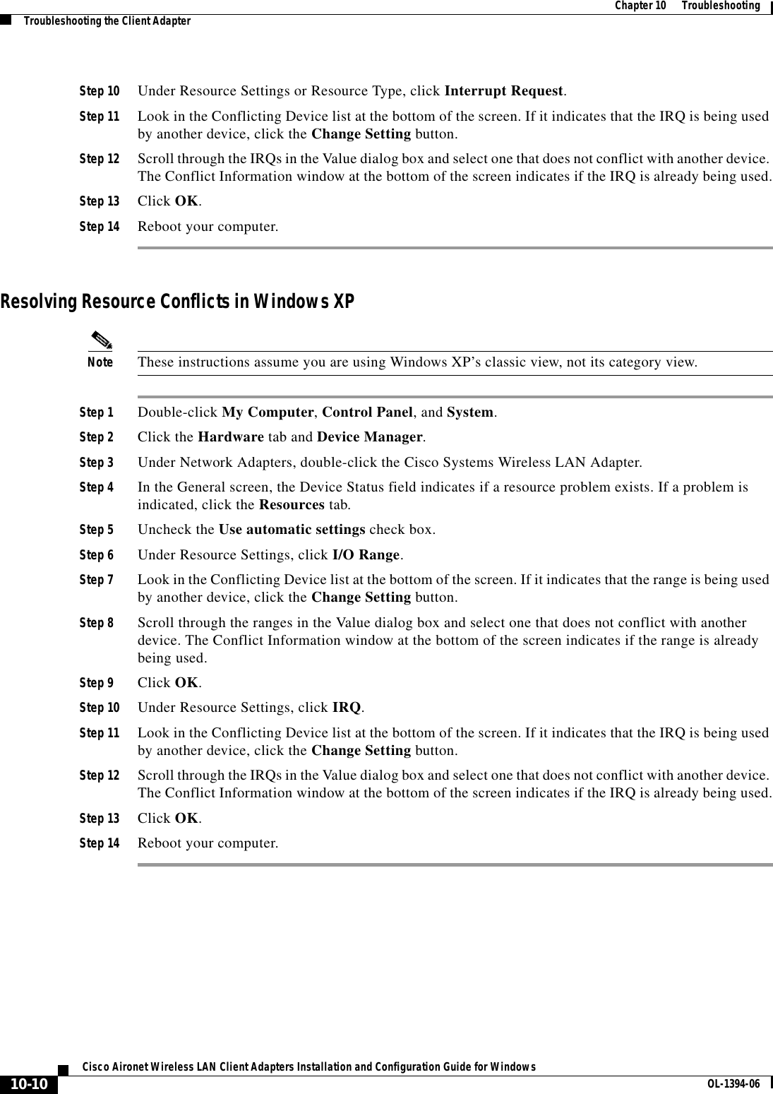
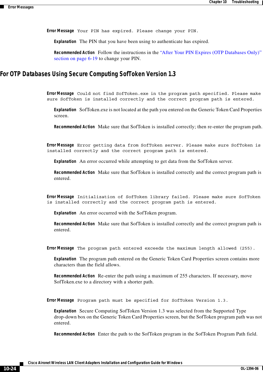
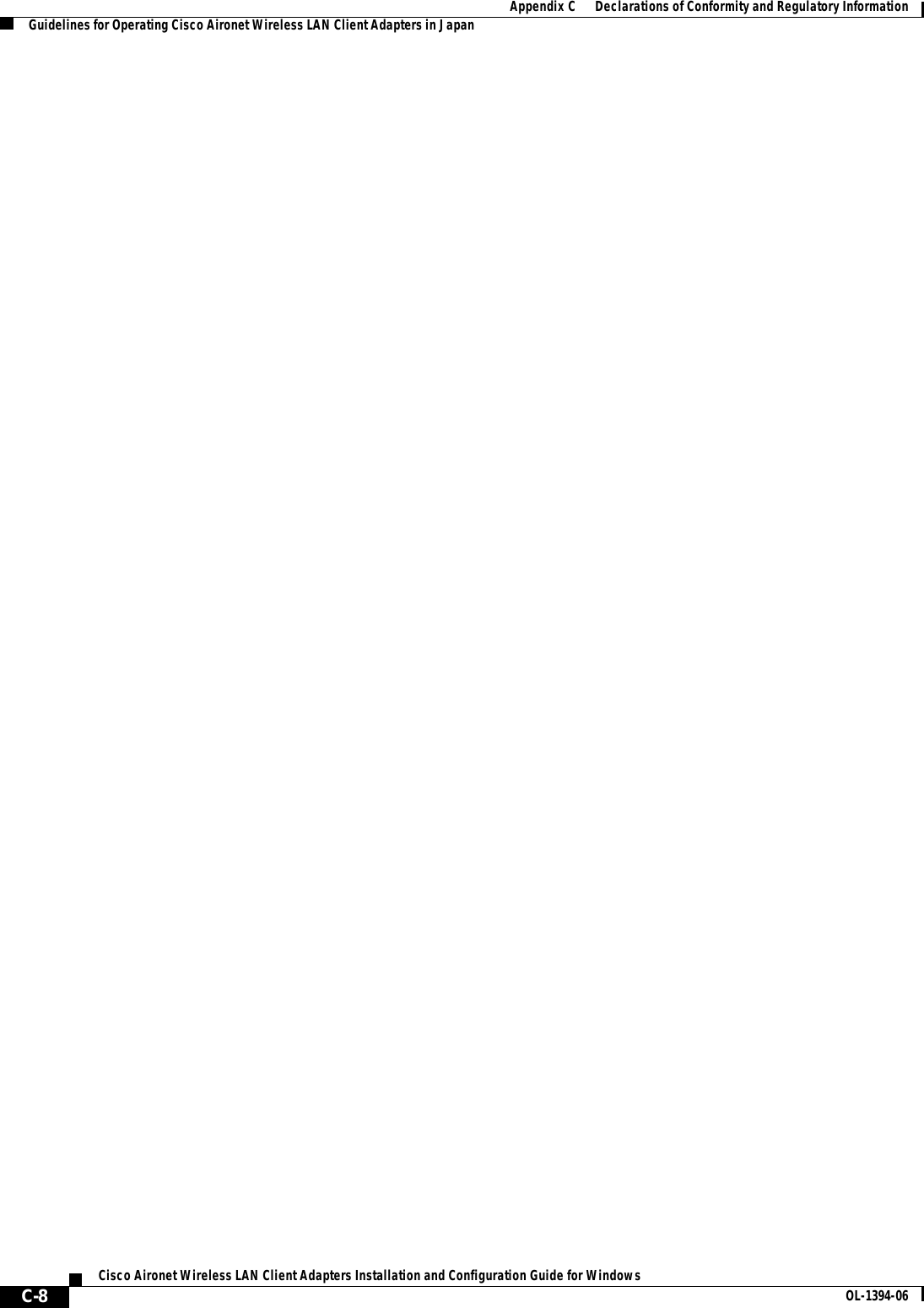
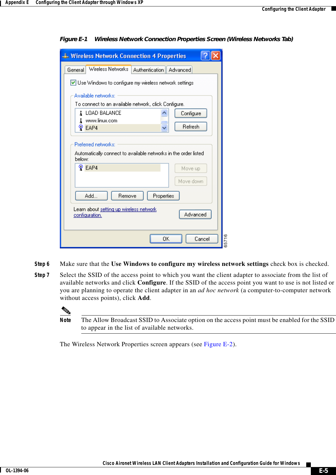
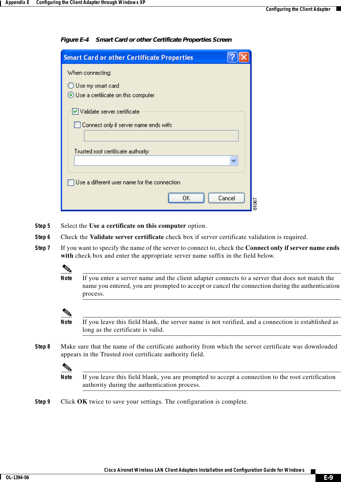
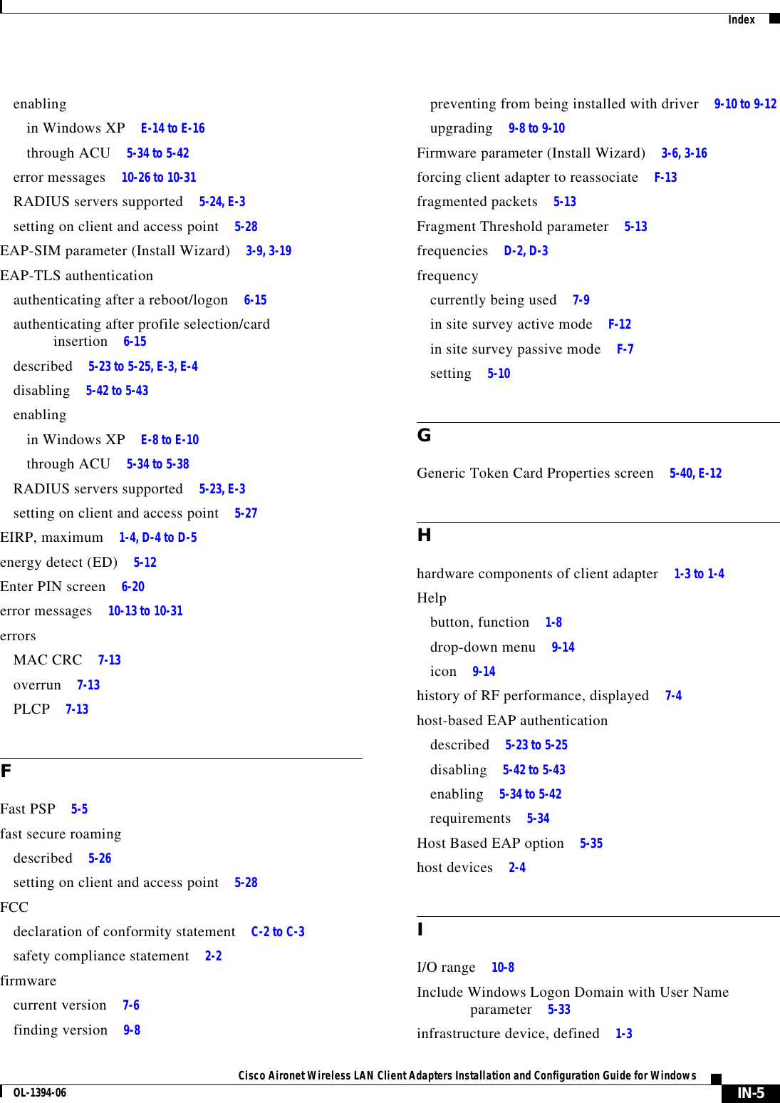
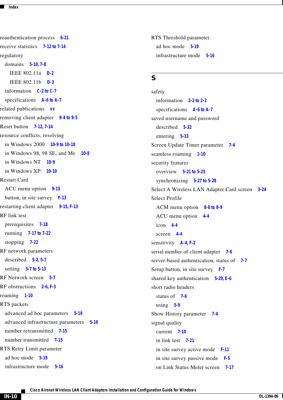
![9-12Cisco Aironet Wireless LAN Client Adapters Installation and Configuration Guide for Windows OL-1394-06Chapter 9 Routine ProceduresClient Adapter Software ProceduresNote The Automatically Load New Firmware When NDIS Driver Is Updated parameter is dependent on the radio type (and the Cardbus slot for PC-Cardbus cards). Therefore, if you insert a client adapter of a different card type (such as a 340 instead of a 350) or insert the same PC-Cardbus card into a different slot, whether or not the driver installs the firmware with which it is bundled depends on how this parameter (or the Disable Firmware Checking parameter) was last set for that card type or card slot.Step 4 Click OK.ACU ProceduresThis section provides instructions for the following procedures:•Opening ACU, below•Exiting ACU, page 9-13•Modifying ACU installation settings, page 9-13•Finding the version of ACU, page 9-13•Adding the ACU icon to or removing it from the desktop, page 9-14•Accessing online help, page 9-14Opening ACUTo open ACU, perform one of the following:•Double-click the Aironet Client Utility (ACU) icon on your desktop.•Select Aironet Client Utility (ACU) from the folder in the Windows Start Menu that you chose during installation [the default location is Start > Program Files > Cisco Systems > Aironet Client Utility (ACU)].•Double-click My Computer > Control Panel > Aironet Client Utility.](https://usermanual.wiki/Xplore-Technologies/IX104-112.WLAN-Manual/User-Guide-342985-Page-182.png)