Xsens Technologies AW-A2 Wireless Awinda Station User Manual
Xsens Technologies B.V. Wireless Awinda Station Users Manual
UserManual.wiki
>
Xsens Technologies
>
AW A2 User Manual
Users Manual
Navigation menu
Upload a User Manual
Namespaces
Wiki Guide
HTML
PDF
Info
Views
User Manual
Discussion / Help
Navigation
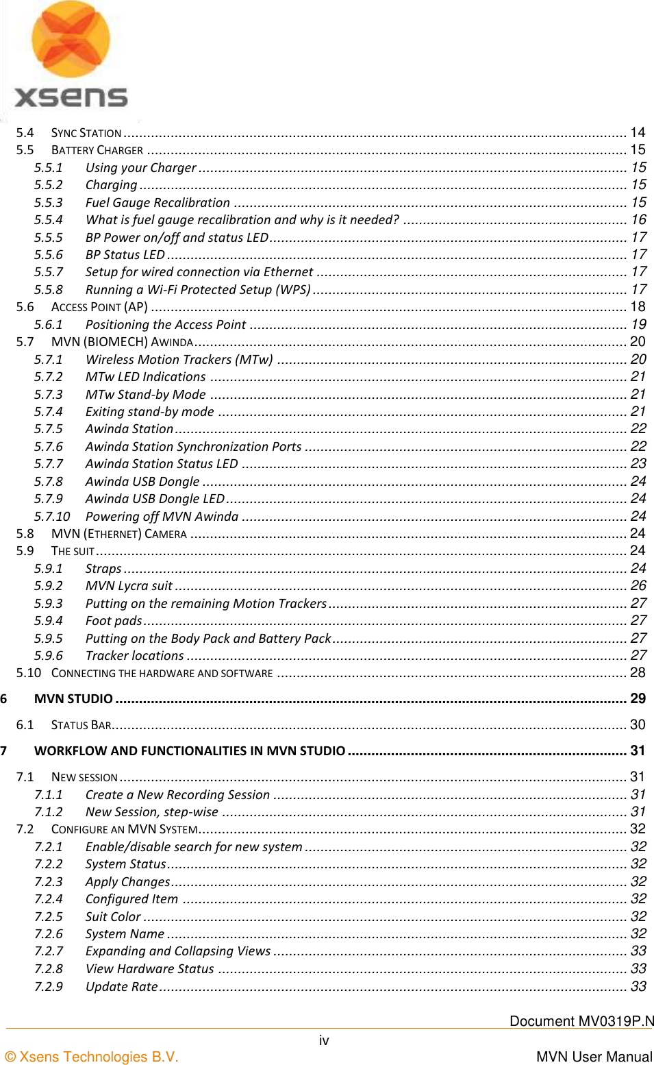

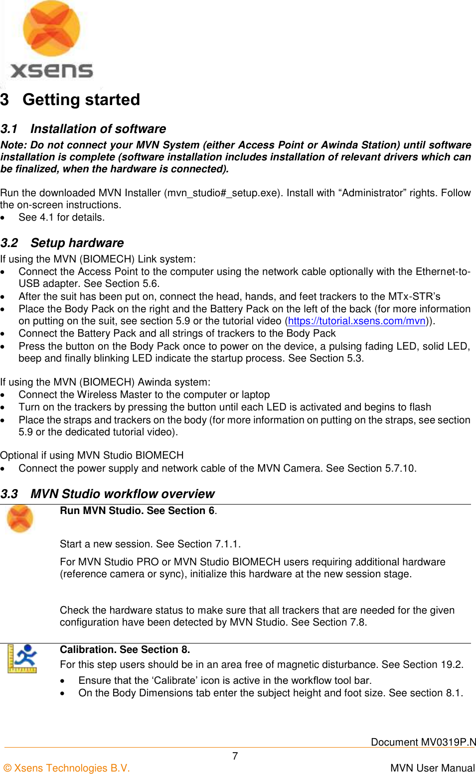


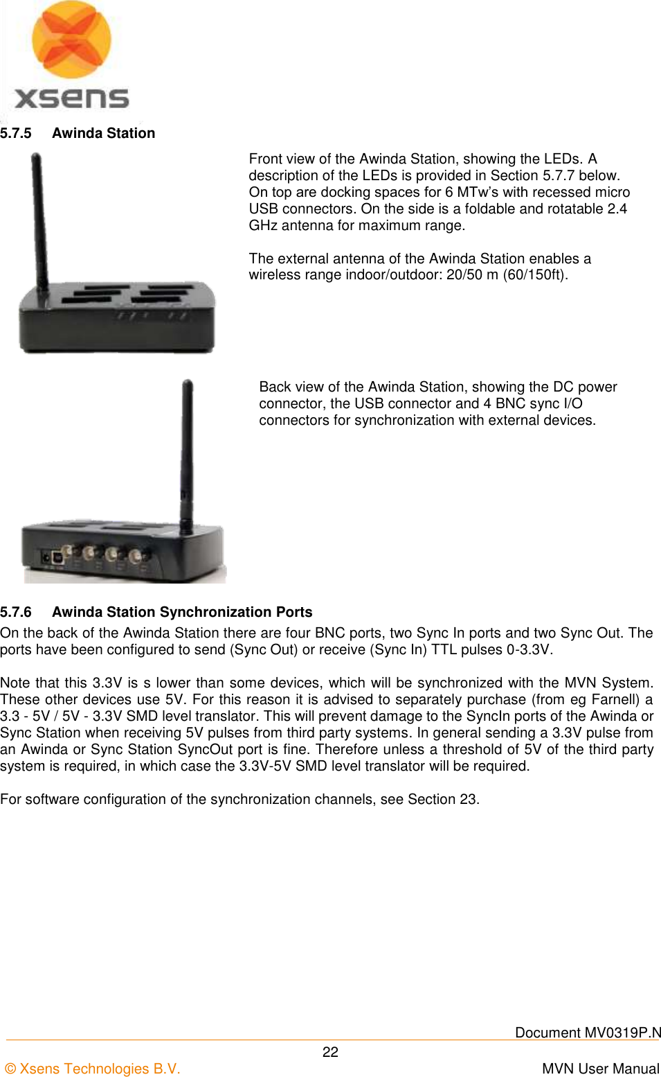
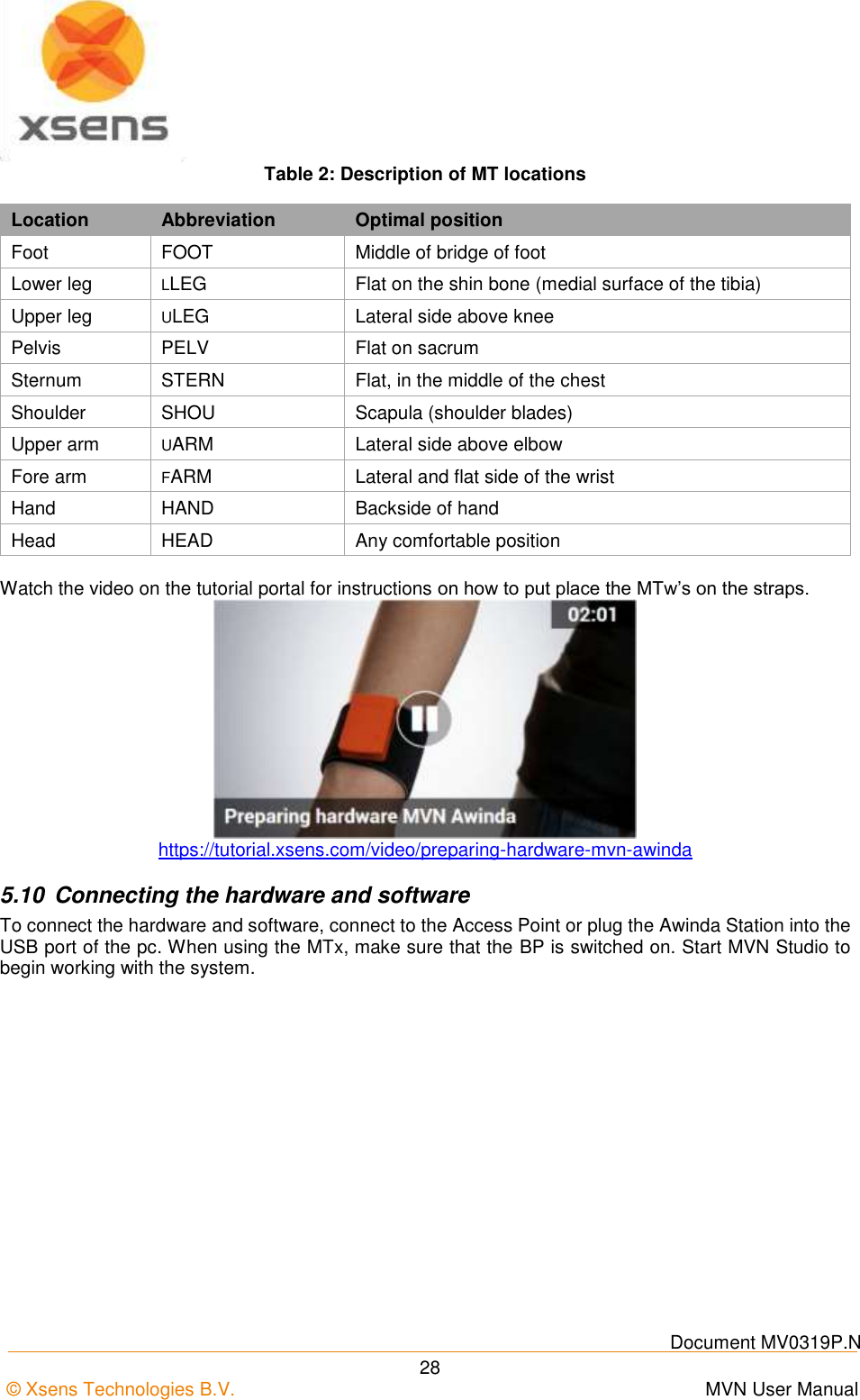
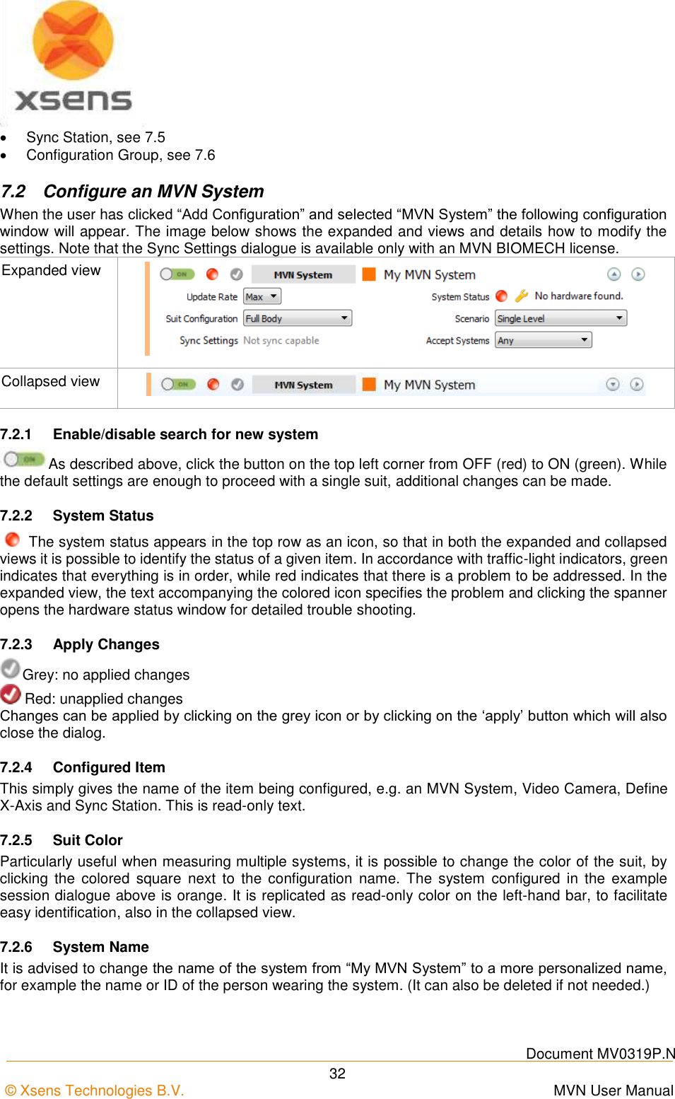
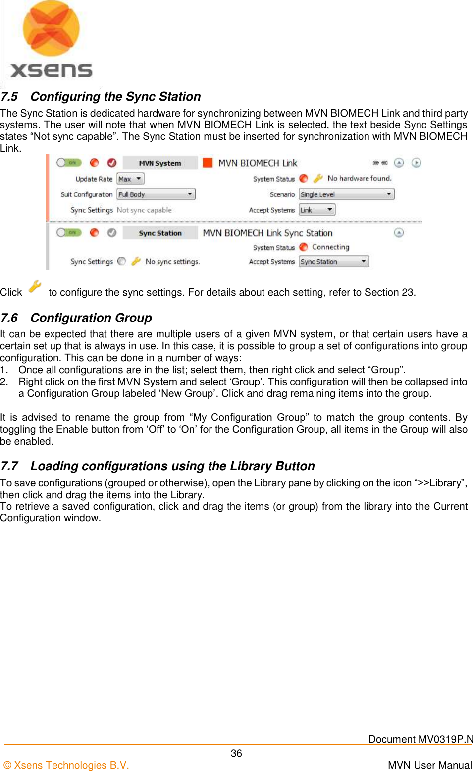
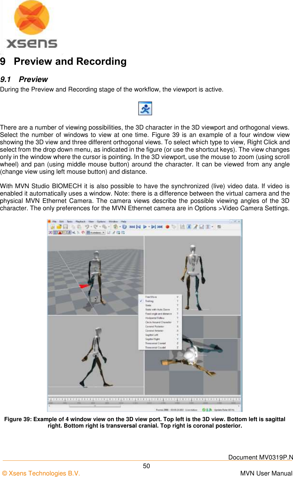
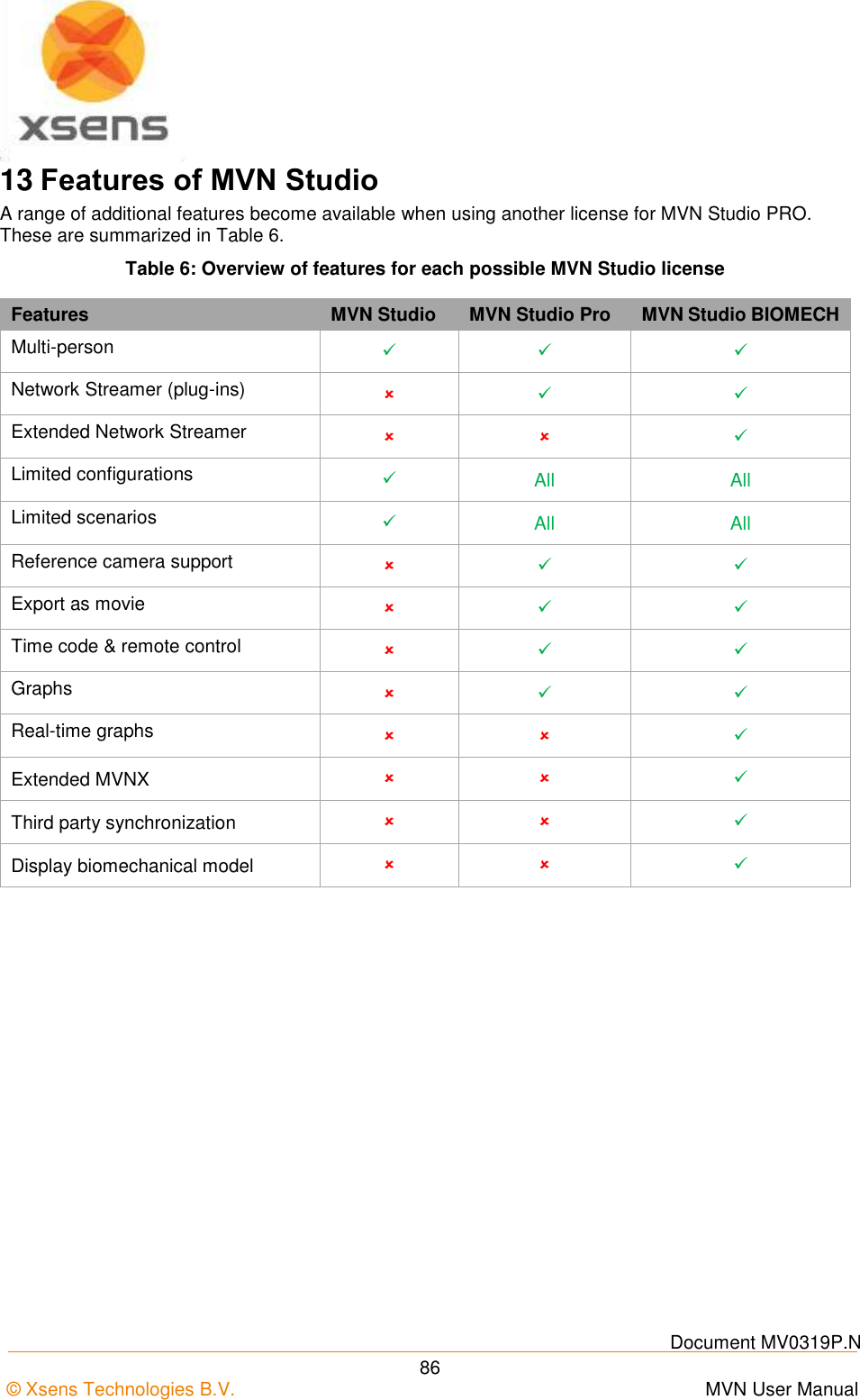
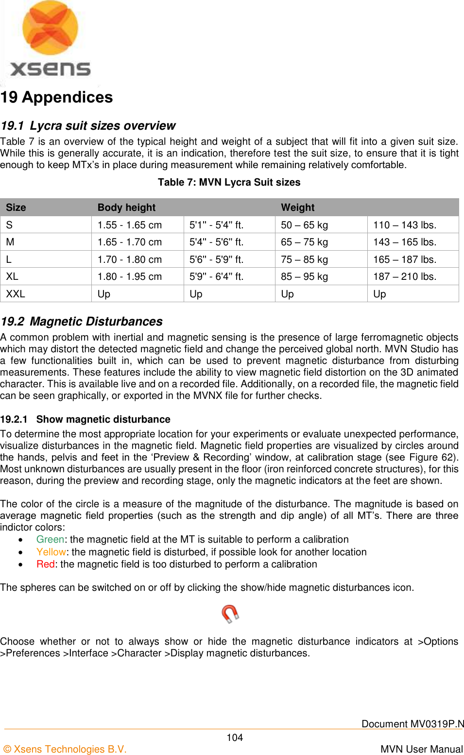
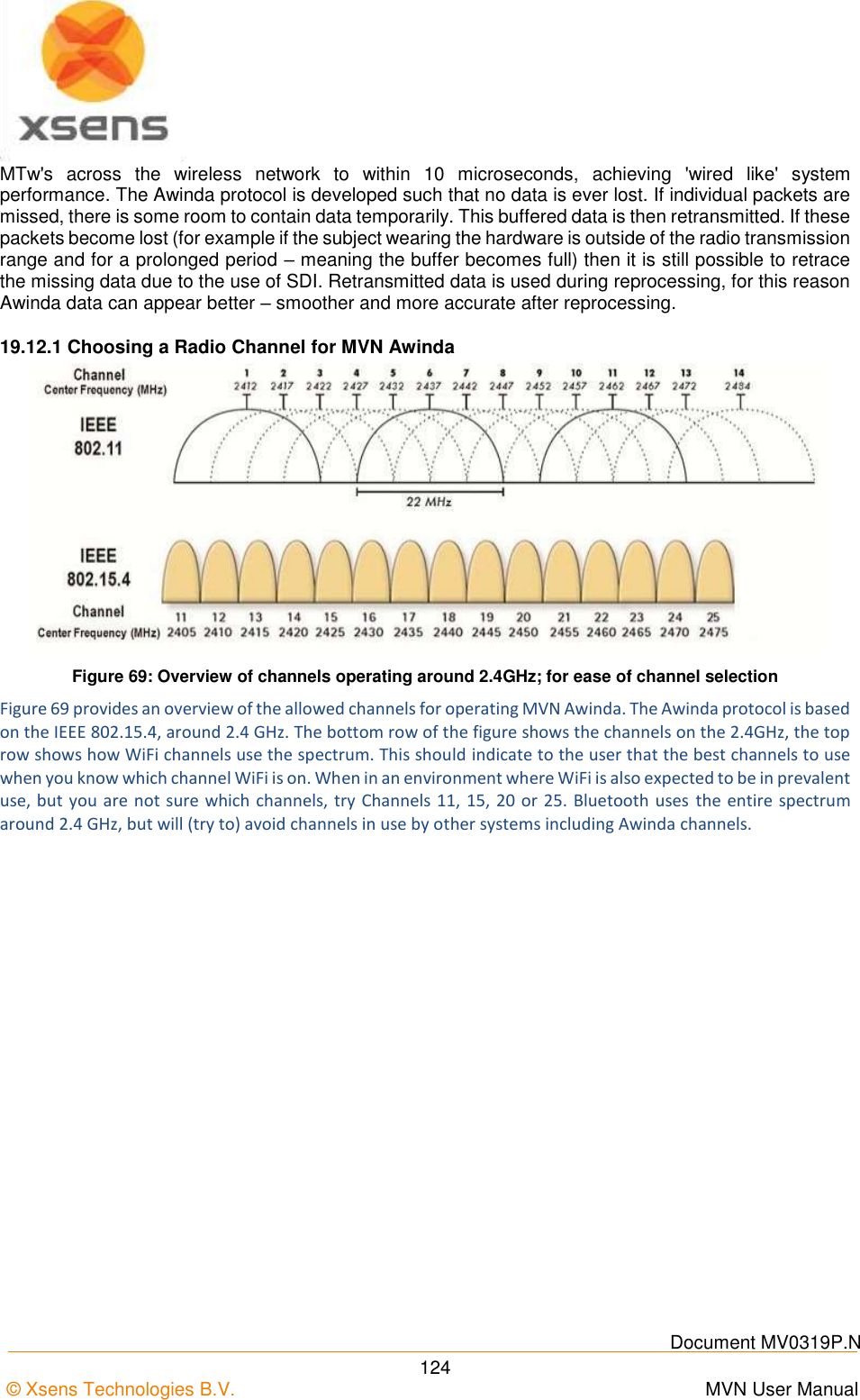
![Document MV0319P.N © Xsens Technologies B.V. MVN User Manual 21 5.7.2 MTw LED Indications The following lists the LED indications of the MTw, which are a combination of the device states and the Awinda protocol states of the MTw. State Description Power-up Blinking. Docked and fully charged ON Charging Slow fade from ON to OFF as a percentage [%] of battery status. A slow cycle means an almost full battery. A quick cycle means an almost empty battery. Scanning Pulsating out of sync with Awinda Station (CONN LED) Connected Slow symmetric ON/OFF toggle in sync with Awinda Station (CONN LED). Measuring Fast symmetric ON/OFF toggle in sync with Awinda Station (CONN LED). Battery Low Quick Triple Pulses, overrides other states until charging again. Flushing Double pulse in sync with Awinda Station (CONN LED). Stand-by OFF. Blinks for 3 s, if motion has been detected, while searching for a radio connection. 5.7.3 MTw Stand-by Mode Following a wireless connection to the Awinda Station or Dongle, the MTw enters measurement mode. If the radio of the Awinda Station or Dongle has been switched off for longer than 30 seconds the MTw will enter stand-by mode. In this mode, the MTw will shut down its power and stop the LED blinking, but monitor change in magnetic field every second. See below for exiting standby mode. 5.7.4 Exiting stand-by mode The MTw will monitor its movement, if there is considerable movement, and there is a signal from an Awinda Station or Dongle, the MTw will become active again. To manually bring the MTw out of stand-by mode, reactivate the radio of the Awinda Station, and move the MTw. A simple 90 degree turn or simply lifting it from the suit case to apply to the subject should be enough.](https://usermanual.wiki/Xsens-Technologies/AW-A2/User-Guide-2695618-Page-31.png)
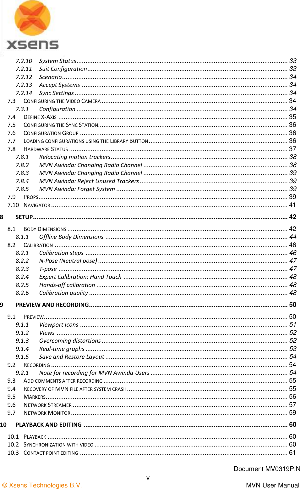
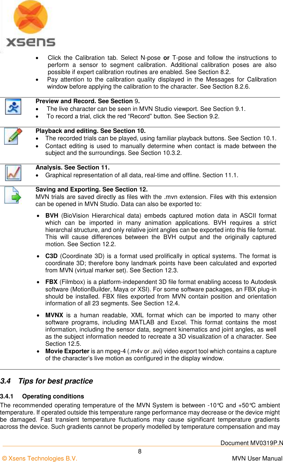
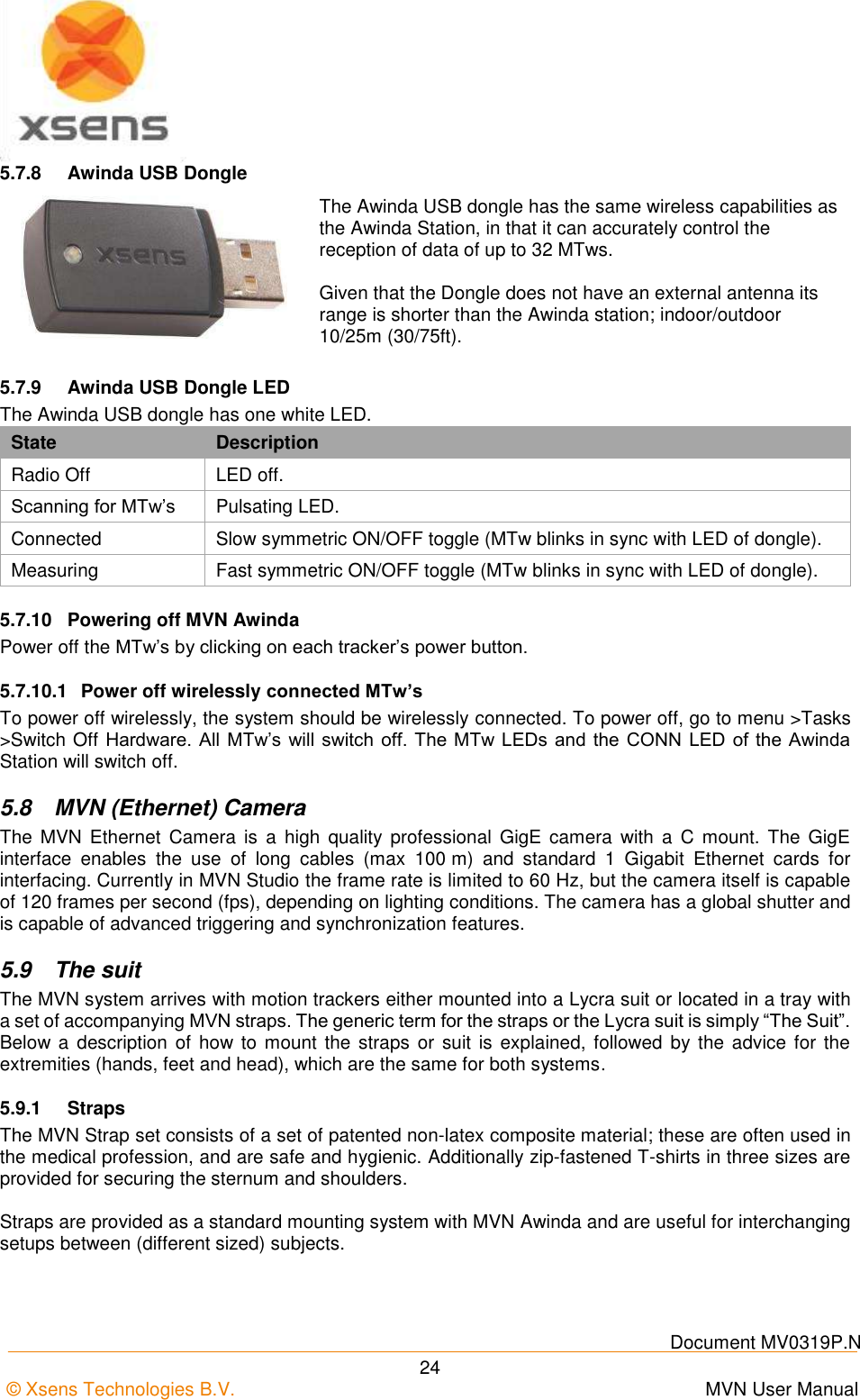
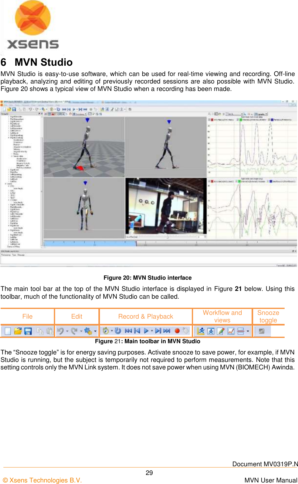
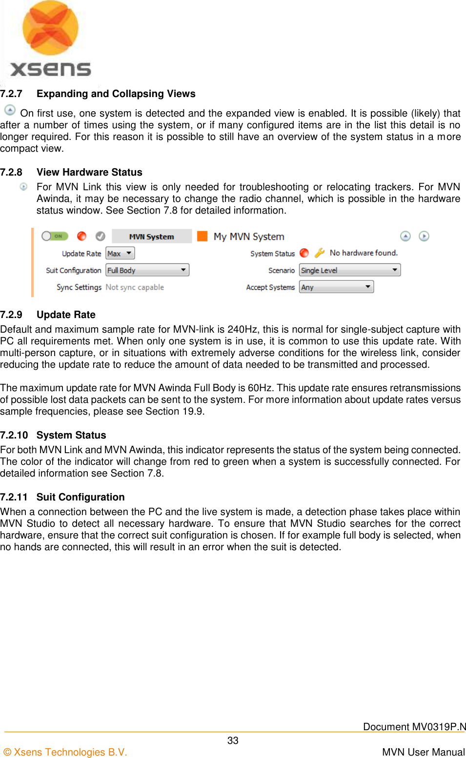
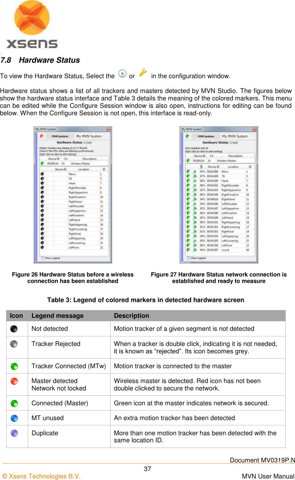
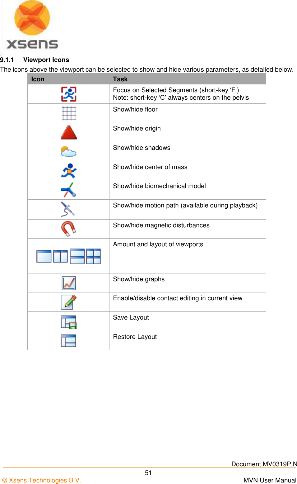
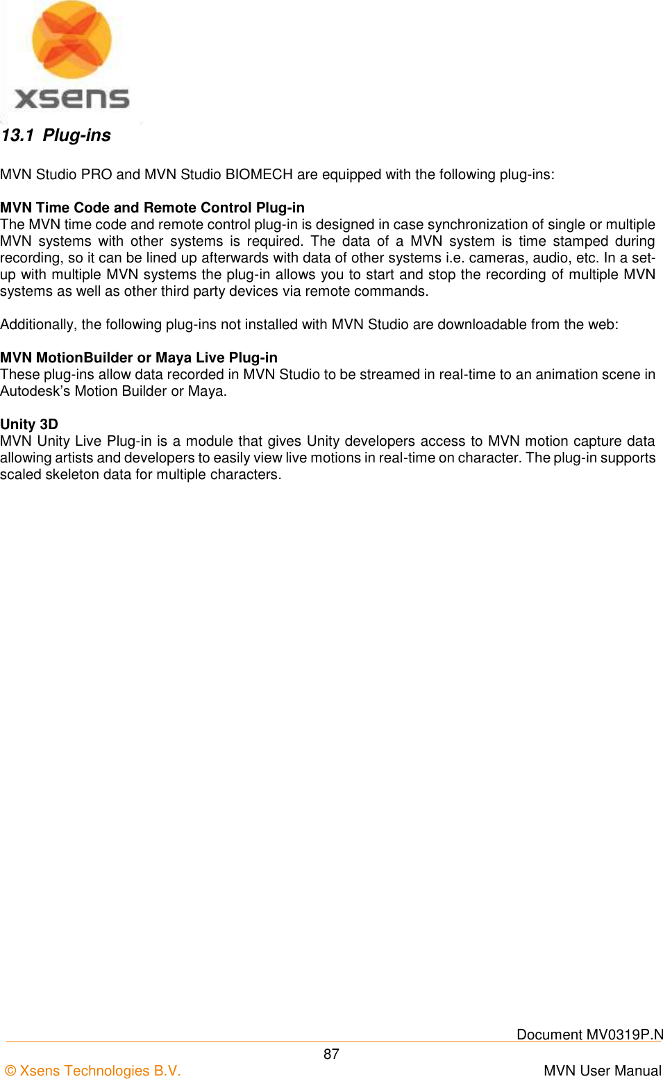
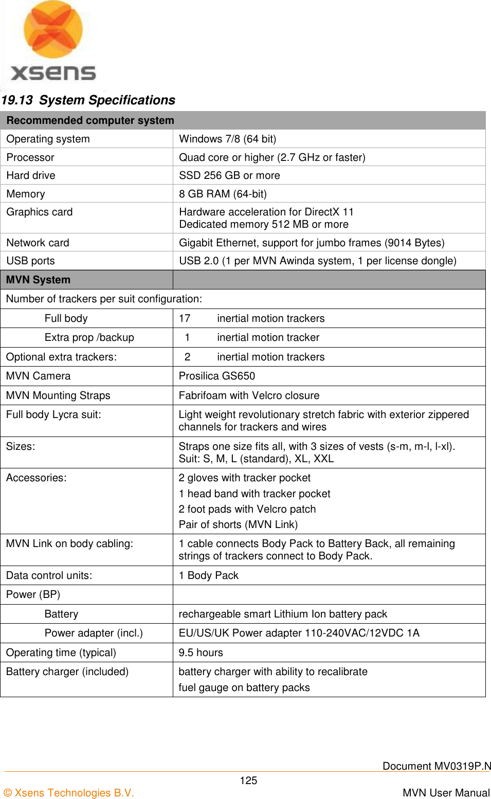
![Document MV0319P.N © Xsens Technologies B.V. MVN User Manual 23 5.7.7 Awinda Station Status LED The Awinda Station has five LED indicators. From right to left, these indicators are: LABEL LED DESCRIPTION CHRG [CHaRGer functionality] OFF When no mains power supply is connected to the Awinda Station. GREEN: When 12V power supply is connected (mains power supply). STAT [STATus of the Awinda Station] OFF OFF: When no power supply is present and when MVN Studio is not started. Power is from mains power supply and / or USB. GREEN: Both USB connection present and MVN Studio running connected to driver. ORANGE: USB connection to host PC is present. RED: Only power supply connected or error has occurred, e.g., a short-circuit of an MTw. EXT [EXTernal connection] OFF Remains off unless external connection made. GREEN: External connection e.g. sync port. CONN OFF OFF: No wireless connection. GREEN slow blinking: (1 blink per second), radio switched on. When MTw connects, MTw LED and CONN LED blink synchronously. Fast blink: Measurement Mode. DATA OFF OFF: No data received. GREEN: Measurement mode. ORANGE: Flushing. Flushing is the action of transferring data that has been stored on the MTw buffer, while the MTw was out of range and unable to transfer data in real-time to the Awinda Station. RED: Recording mode is active. This allows the remote monitoring that the host PC has initiated a recording successfully. Note: The power supply is needed to charge docked MTw’s or to change between power off and power on, of docked MTw’s. Only the power supply is needed for charging purposes (USB is not needed in this case). Power supply and USB connection are required for firmware updates or location reassignment of MTw’s. Power supply is not needed for wireless communication (e.g. measurement/recording).](https://usermanual.wiki/Xsens-Technologies/AW-A2/User-Guide-2695618-Page-33.png)
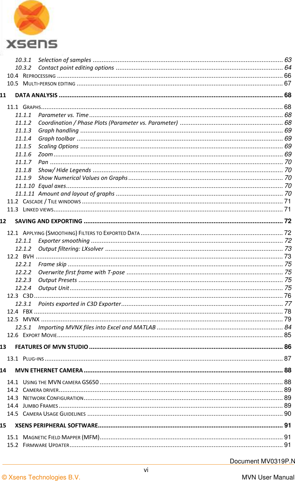
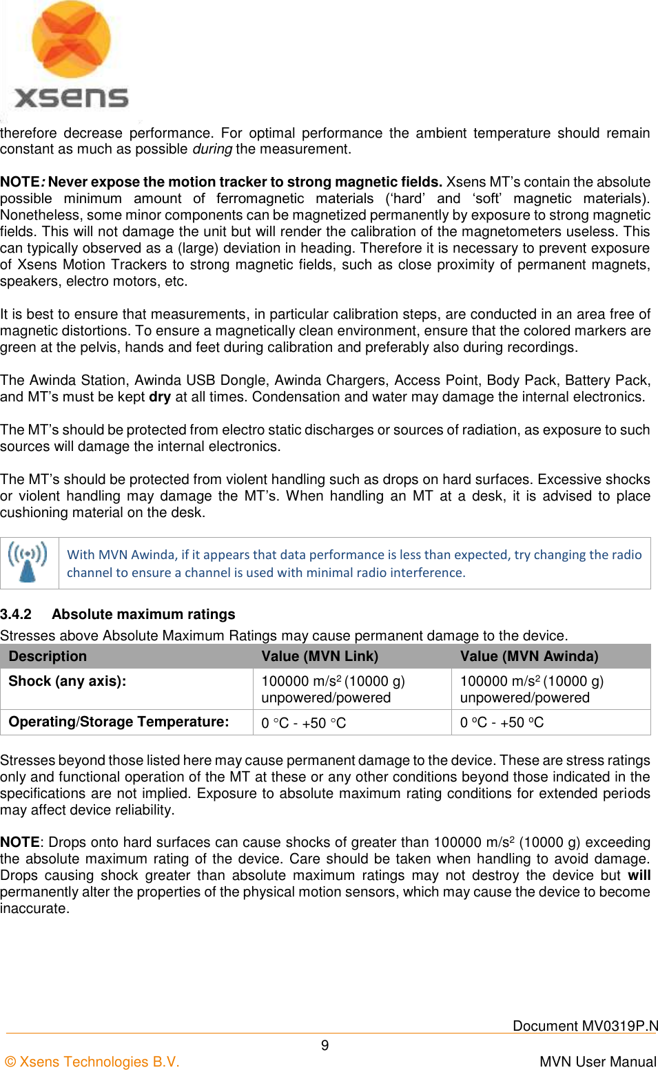
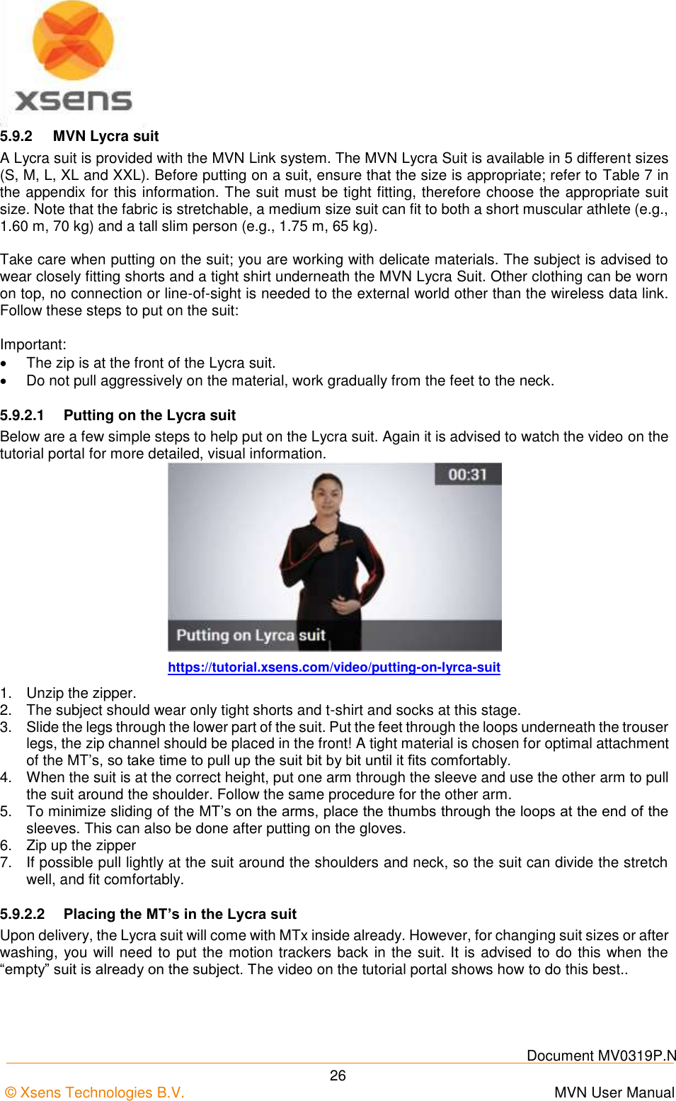
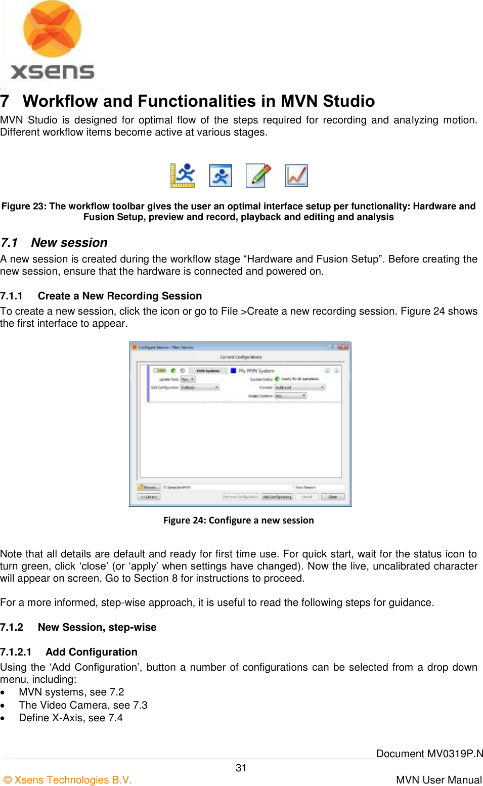
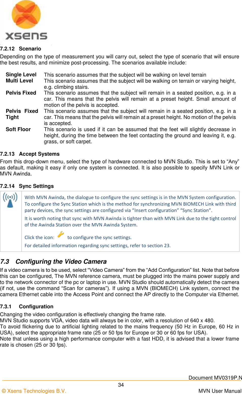
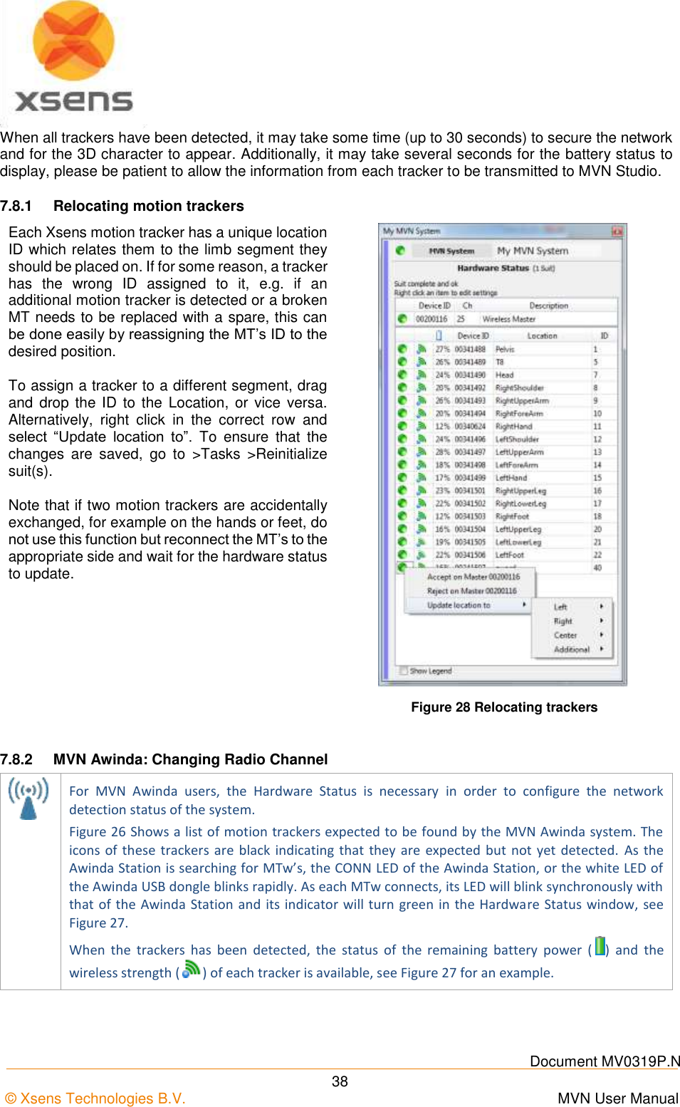
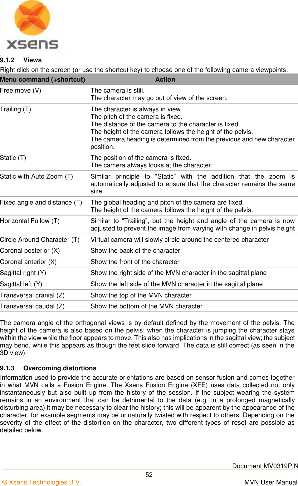
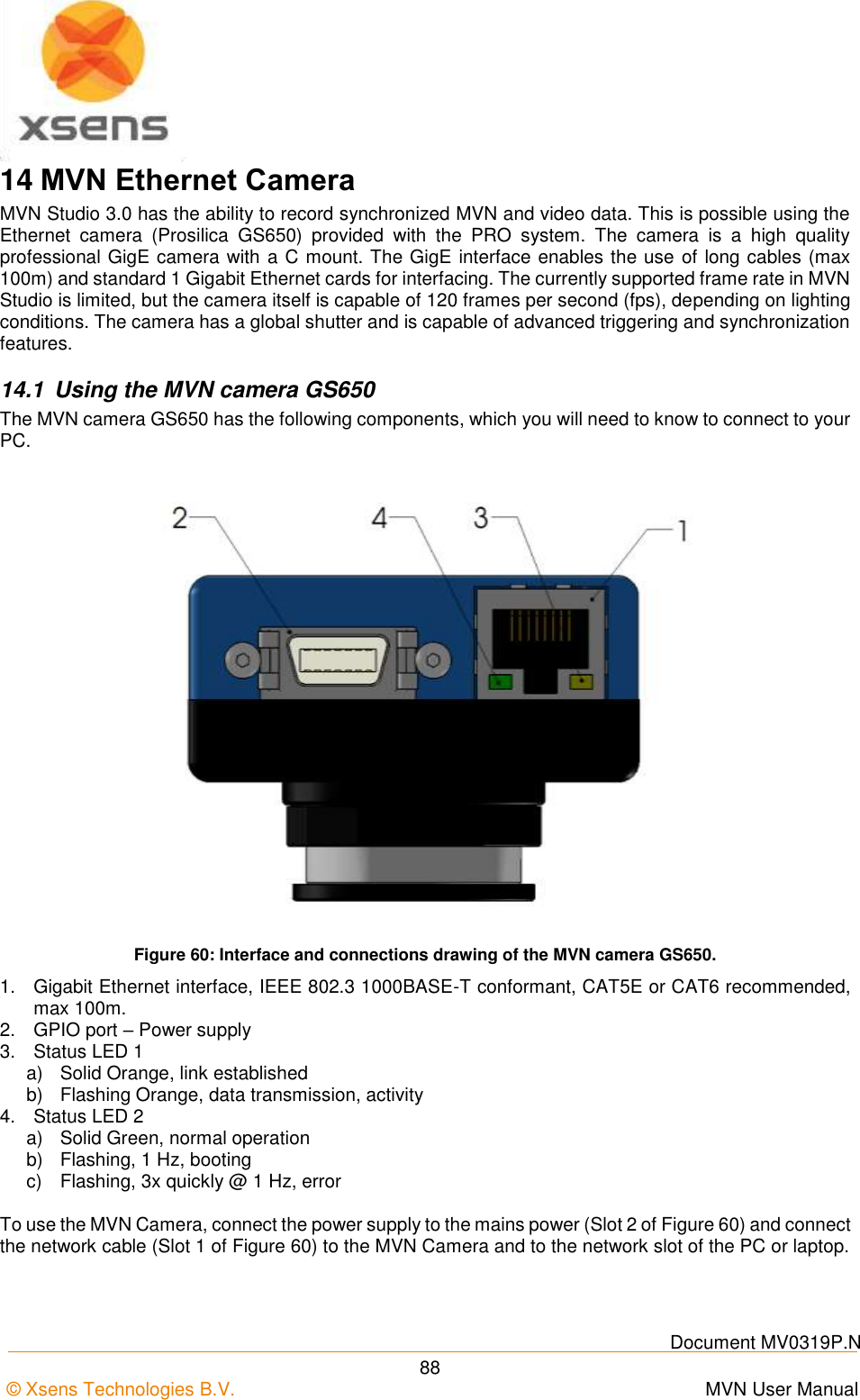
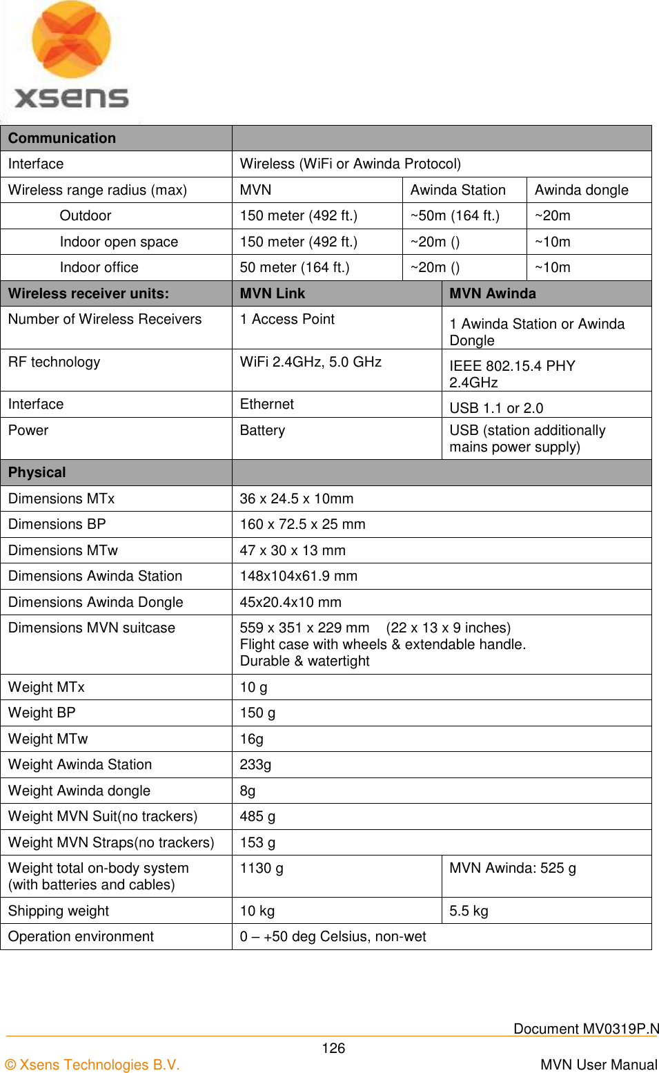
![Document MV0319P.N © Xsens Technologies B.V. MVN User Manual 25 Straps are suitable for a majority of the adult population and can be placed directly on the skin for the close contact, or on top of the clothing for comfort. If worn over clothing, it is advisable to wear relatively tight-fitting clothes. The motion trackers are provided with a code indicating segment position. ‘L’ or ‘R’: left or right side of the body. Segment: An abbreviation of the segment name. While the straps are not labelled, the dimensions give an indication of their intended locations. Segment Width [cm] Length [cm] Pelvis 10 140 Upper Leg 10 72 Lower Leg 5 55 Upper Arm 5 55 Forearm 5 30 5.9.1.1 Putting on the Straps Below are a few simple steps to help put on the straps. It is advised to watch the tutorial video for more detailed and visual information. https://tutorial.xsens.com/video/placing-straps It is recommended to begin by putting on the top. Since the sternum and shoulder trackers are attached to Velcro patches on a zip-fastening t-shirt, it is advised to secure this garment before attaching the upper arm straps. For the arms, legs and pelvis: Straps should first be placed (tightly) onto the limb in question, fasten the tracker in place then wrap the remaining length of the strap tightly around the limb and fasten using the Velcro tab. It is necessary to have assistance for positioning the motion trackers of the shoulder blades after the zip on the vest has been secured. It is also advisable to have assistance for accurate positioning of the tracker at the pelvis, while the wearer (or second assistant) wraps the remaining length of the strap around the waist. Check that the Straps are fastened tightly enough to the body. To do this, the subject wearing the straps should walk, run or perform sample movements to be measured. If the straps become loose, re-tighten them and repeat the check. NOTE: When tightening the straps, pull the strap from the center of the length rather than at the end!](https://usermanual.wiki/Xsens-Technologies/AW-A2/User-Guide-2695618-Page-35.png)
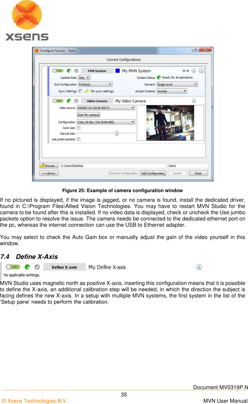
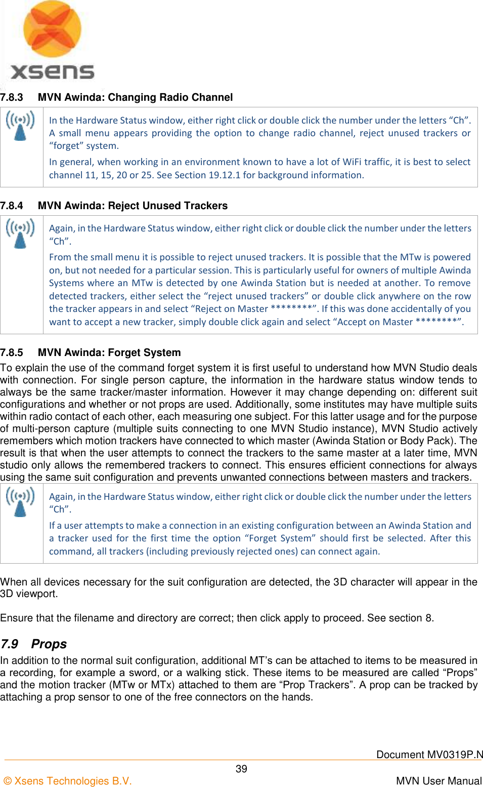
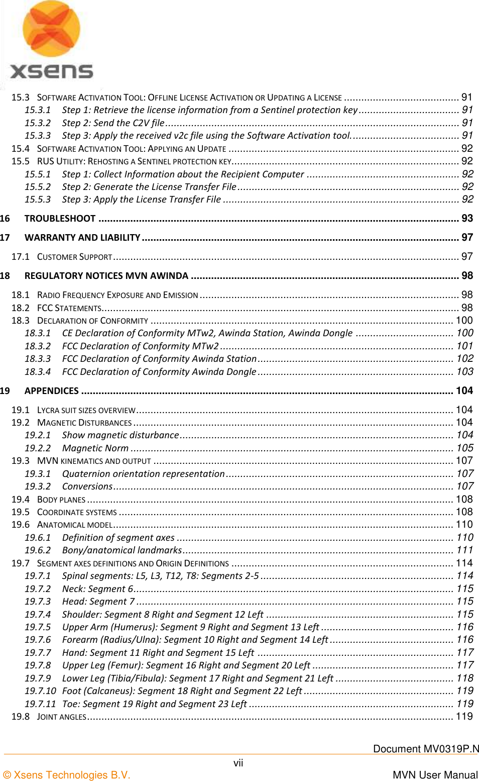
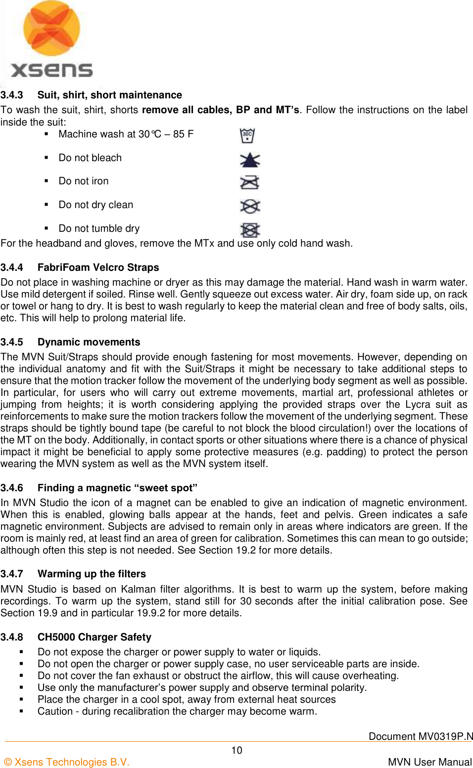
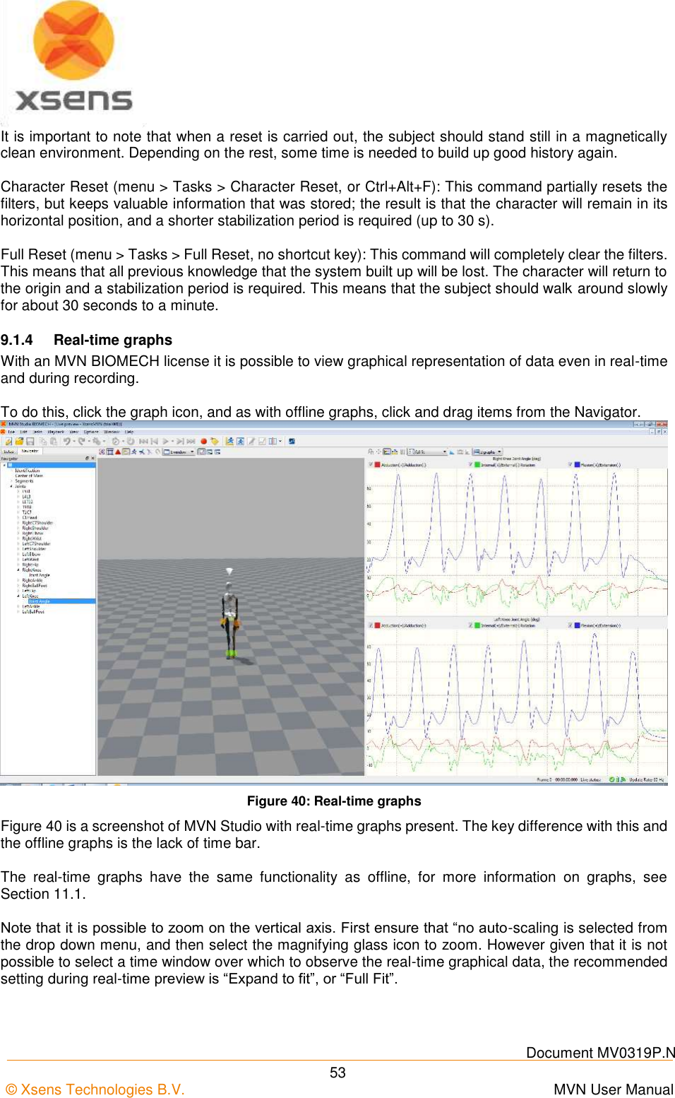
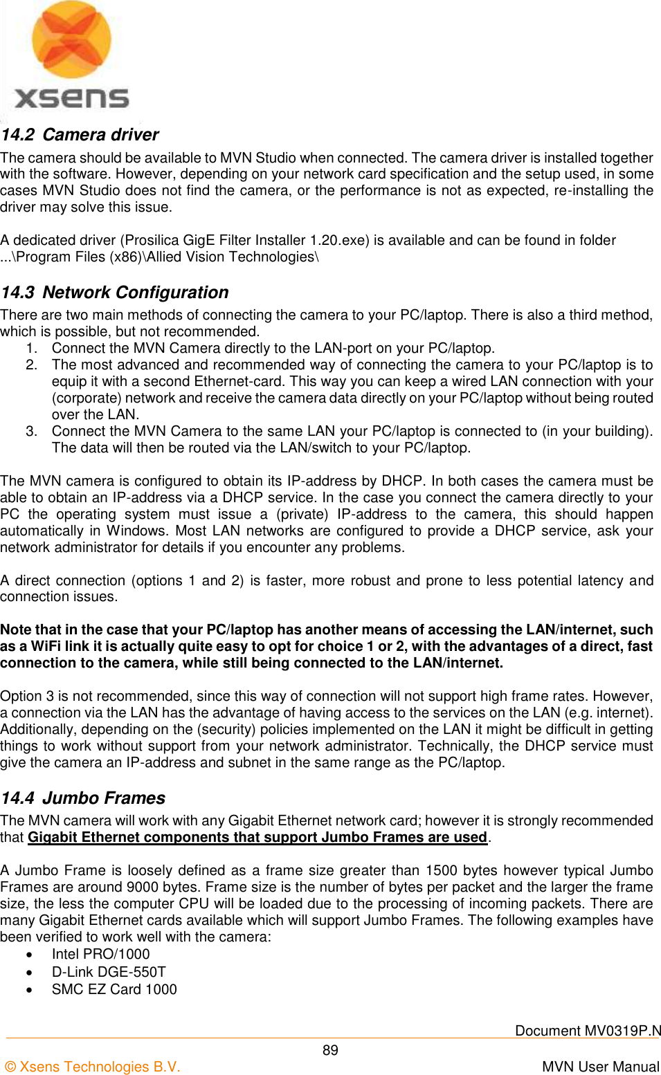
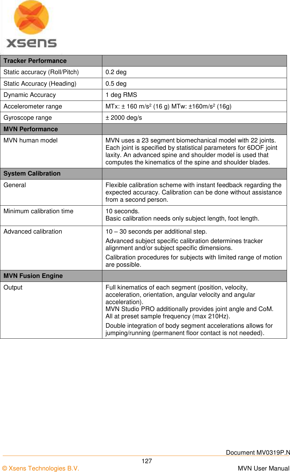
![Document MV0319P.N © Xsens Technologies B.V. MVN User Manual 40 The prop tracker must be configured in the menu Options >Configure Props. Here, the type of prop can be selected (crutch, sword, gun, diemaco, golf club, prop [this is simply a right-handed axis]), which can be assigned to a given suit and a given motion tracker ID. Generally the motion tracker on the prop is detected automatically when clicking ‘Apply’ in the Prop Configuration window. If this does not occur, go to Tasks >Re-initialize suit(s). The prop mesh (the on-screen image of the prop sensor) can be connected to any defined point on a body segment. The prop can be rotated freely but will always follow the position of the selected point. By selecting the ‘or’ option, the prop tracker can be swapped between two segments, for example the right and left hand (see the example in Figure 29). MVN Studio will automatically detect the side on which the motion tracker is connected. Figure 29: Prop configuration menu For example, when holding a sword, the blade may point forwards. When holding a gun, the barrel will point downwards. Look at the X, Y arrows as indicated in the images below. The prop tracker should be mounted onto the prop such that two sides of the casing are parallel with the prop. For example, mount the prop tracker on the flat side of a sword with one axis aligned with the blade of the sword. Then, the orientation of the motion tracker can be set according to the natural orientation of the physical prop when holding it while in an N-pose.](https://usermanual.wiki/Xsens-Technologies/AW-A2/User-Guide-2695618-Page-50.png)
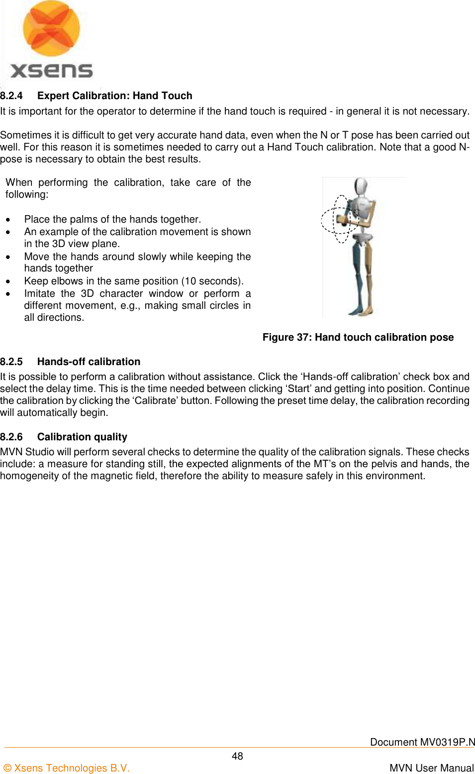
![Document MV0319P.N © Xsens Technologies B.V. MVN User Manual 47 calibration). For short recordings, the drift of the character is typically limited to a few cm. With multi-person capture, the characters can drift apart after a while. Usually this can be fixed in the animation package used for retargeting the motion data to a virtual character. To reset the position of the characters in between recordings, select the character in the navigator, ask the subject to return to the marked position on the floor and select menu > Tasks > ‘Move Character to Origin’ , or press ‘Ctrl-0’ (Ctrl+[Zero Key]). 8.2.2 N-Pose (Neutral pose) The N-Pose calibration is a basic calibration. It can be performed as a stand-alone calibration or before the hand-touch. When performing the calibration, take care of the following: Stand upright on a horizontal surface Feet parallel, one foot width apart. Knees above feet. Hips above knees. Back straight. Shoulders above hips; do not pull the shoulders up. Arm straight alongside body (vertically), thumbs forwards. Check the correct attitude of the arms by flexing and extending the elbows. The forearms should move only in the vertical (sagittal) plane with the palms of the hands facing each other. Face forward. Do not move during the calibration procedure. Following the calibration, if the legs of the 3D character are crossed, when the feet are together then the feet were too far apart during the calibration. Repeat the calibration procedure with the feet closer together for an improved result. Figure 35: N-Pose 8.2.3 T-pose The T-pose is the other basic calibration pose. This is recommended if the subject cannot hold the arms vertically near the body. When performing a calibration, take care of the following: Stand upright on a horizontal surface. Feet parallel, one foot width apart. Knees above feet. Hips above knees. Back straight. Shoulders above hips; do not pull the shoulders up. Arms extended horizontally, thumbs forwards. Check the correct attitude of the arms by flexing and extending the elbows. The forearms should move in the horizontal (transverse) plane. Face forward. Pay attention to symmetry, for example, keep the arms at an equal height. Do not overextend the elbow, since flexion/extension may be projected in other axes. The wrists, elbows and shoulders should all be on a single line. Figure 36: T-pose](https://usermanual.wiki/Xsens-Technologies/AW-A2/User-Guide-2695618-Page-57.png)
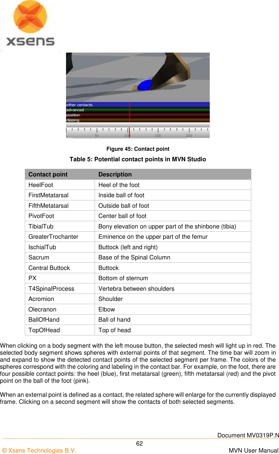
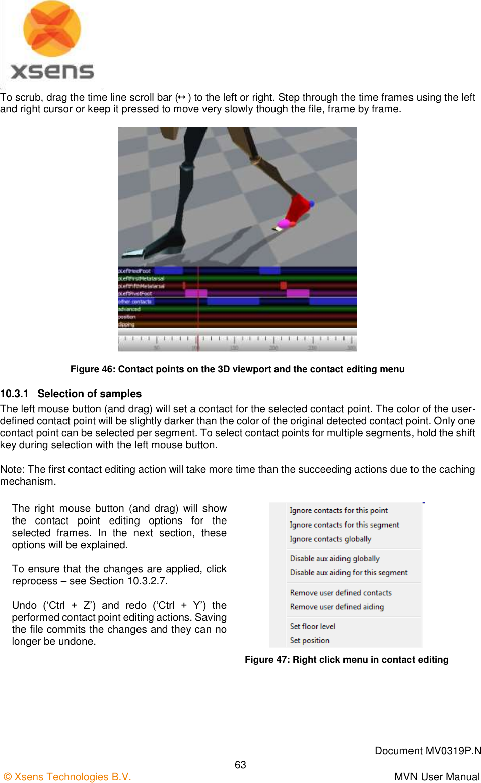
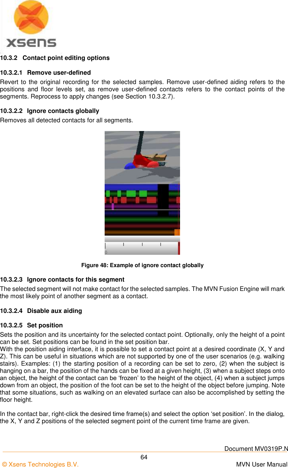
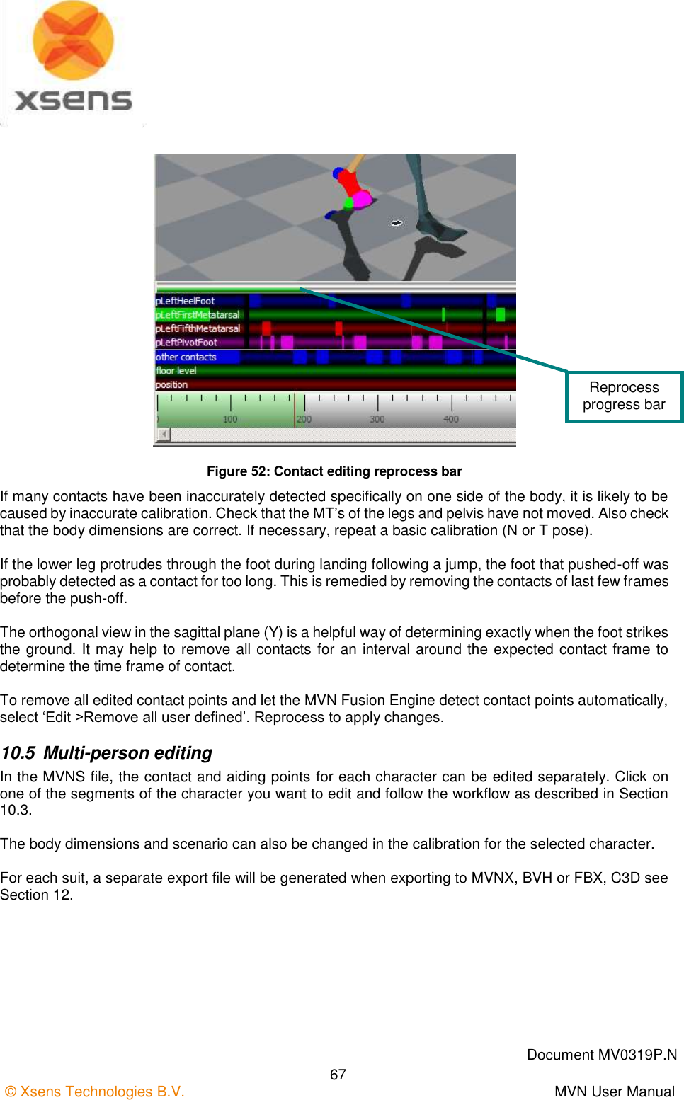
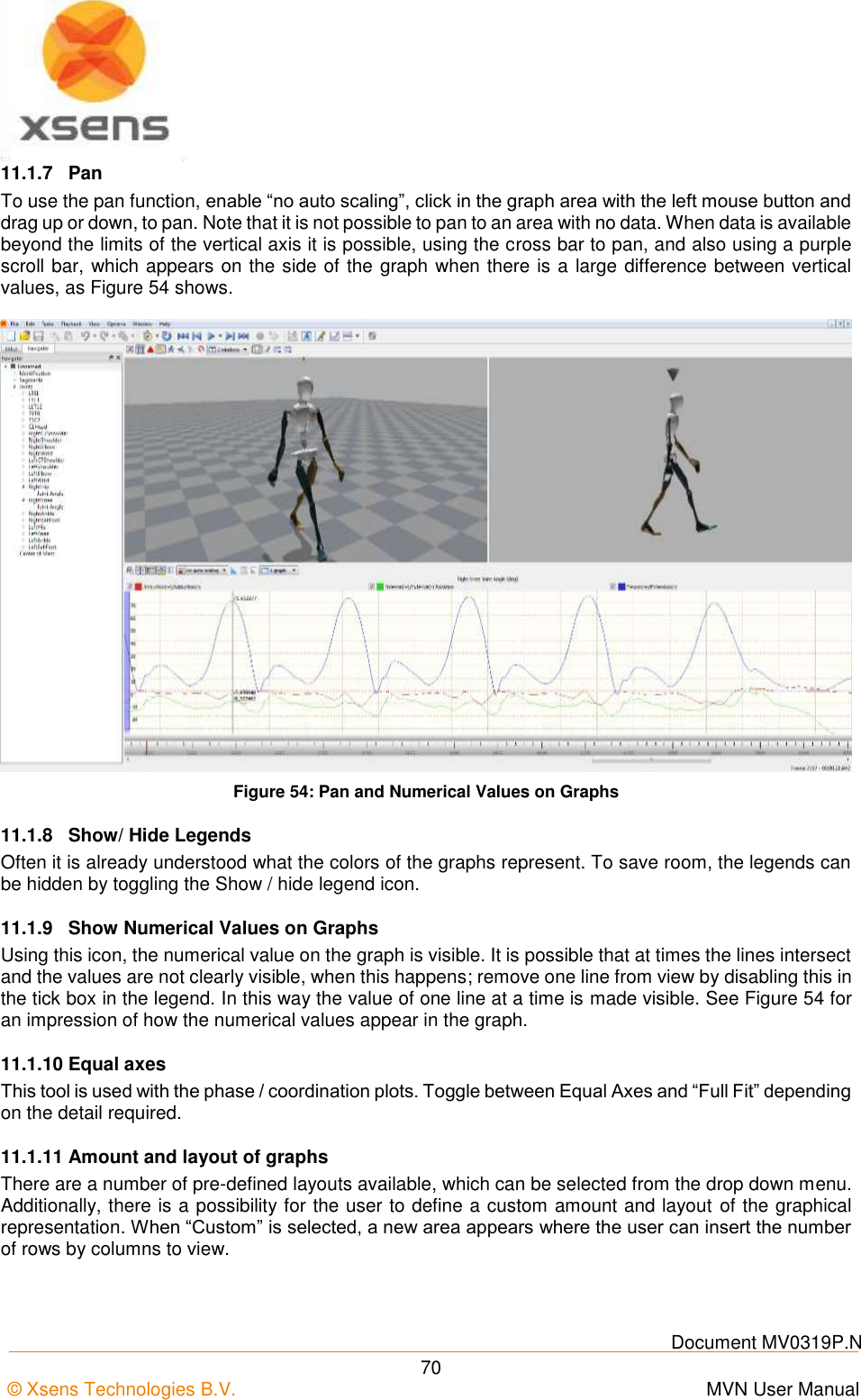
![Document MV0319P.N © Xsens Technologies B.V. MVN User Manual 61 However, if there is a larger offset between the MVN and video data, time-synchronization can be manually corrected using the sliding bar under the video. Drag the bar or use the numbers or the arrows to change the offset [ms]. The offset is applied to the whole file. Any clock skew between the camera and the MVN system is automatically estimated and corrected. Figure 44: Video synchronization sliding bar 10.3 Contact point editing The MVN Fusion Engine uses external contacts of the body with its surroundings to minimize position drift of the computed body model with respect to the Origin (defined by starting point). A number of points on the anatomical model have been defined that are likely to make contact with the external world. An overview of these potential contact points is given in Table 5. The detection of external contacts is based on measured kinematics of relevant body parts. In some cases, e.g., when a recording is made on different floor levels (e.g. stair climbing), it can be desirable to overrule the automatically detected contact points. Note that with MVN files recorded with earlier versions of MVN Studio, it is possible that not all points will be available. Examples of contact point editing steps are given in Section 20. During Playback and Editing, four default bars appear above the timeline, indicating presence of contact points, advanced (floor level), position, and clipping edits (Figure 45). If there is a contact, the contact will be shown in the viewport with a large blue sphere. When hovering above the ‘other contacts’ bar a tool tip pops up indicating which contact point is active.](https://usermanual.wiki/Xsens-Technologies/AW-A2/User-Guide-2695618-Page-71.png)
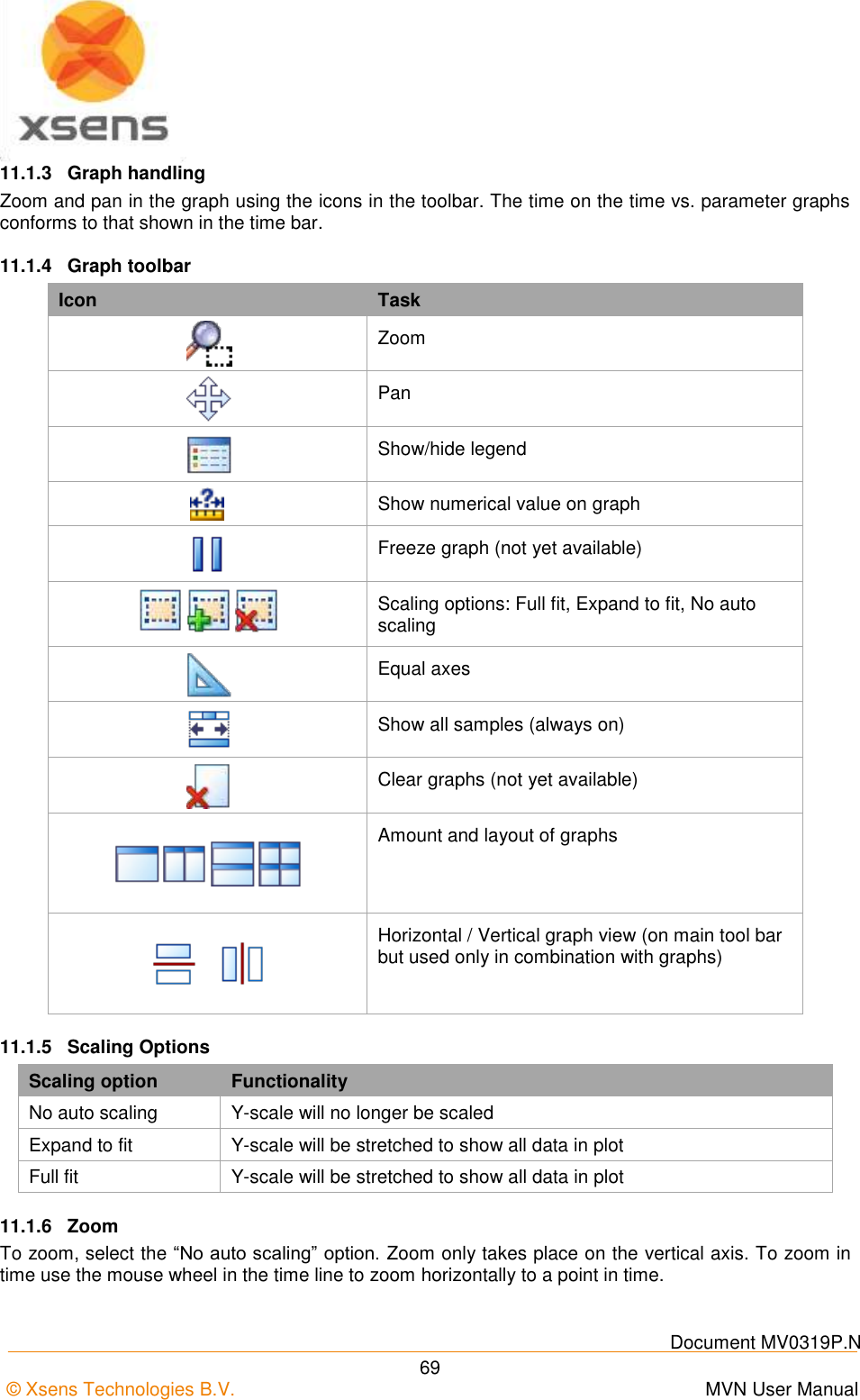
![Document MV0319P.N © Xsens Technologies B.V. MVN User Manual 68 11 Data Analysis The final stage of the work flow is ‘Data Analysis’. The major feature of the analysis stage is kinematic graphs. 11.1 Graphs In the analysis workflow stage, a graph appears in the interface. To view a graph of a given parameter, click and drag the parameter from tree view to the graph. Two types of graphs are possible: time vs. parameter and parameter vs. parameter (Coordination [or phase] Plots). 11.1.1 Parameter vs. Time Drag and drop a parameter with the left mouse button to create a parameter vs. time graph. Click on the colored boxes in the legend to disable/enable data in a given plane. 11.1.2 Coordination / Phase Plots (Parameter vs. Parameter) Drag and drop a parameter with the right mouse button to the horizontal or vertical of the graph to create a parameter vs. parameter graph. Select the variable to plot from the menu. On the remaining axis, another axis of the parameter will be displayed as default. Repeat the process to plot the desired parameter on the remaining axis. See Figure 53 for an example of graph types. Figure 53: 2D graphs: Time vs. Parameter on the left hand side and parameter vs. parameter on the right hand side Note that graphs show the angular velocity in degrees per second. In MVNX files, the angular velocity is exported in radians per second.](https://usermanual.wiki/Xsens-Technologies/AW-A2/User-Guide-2695618-Page-78.png)
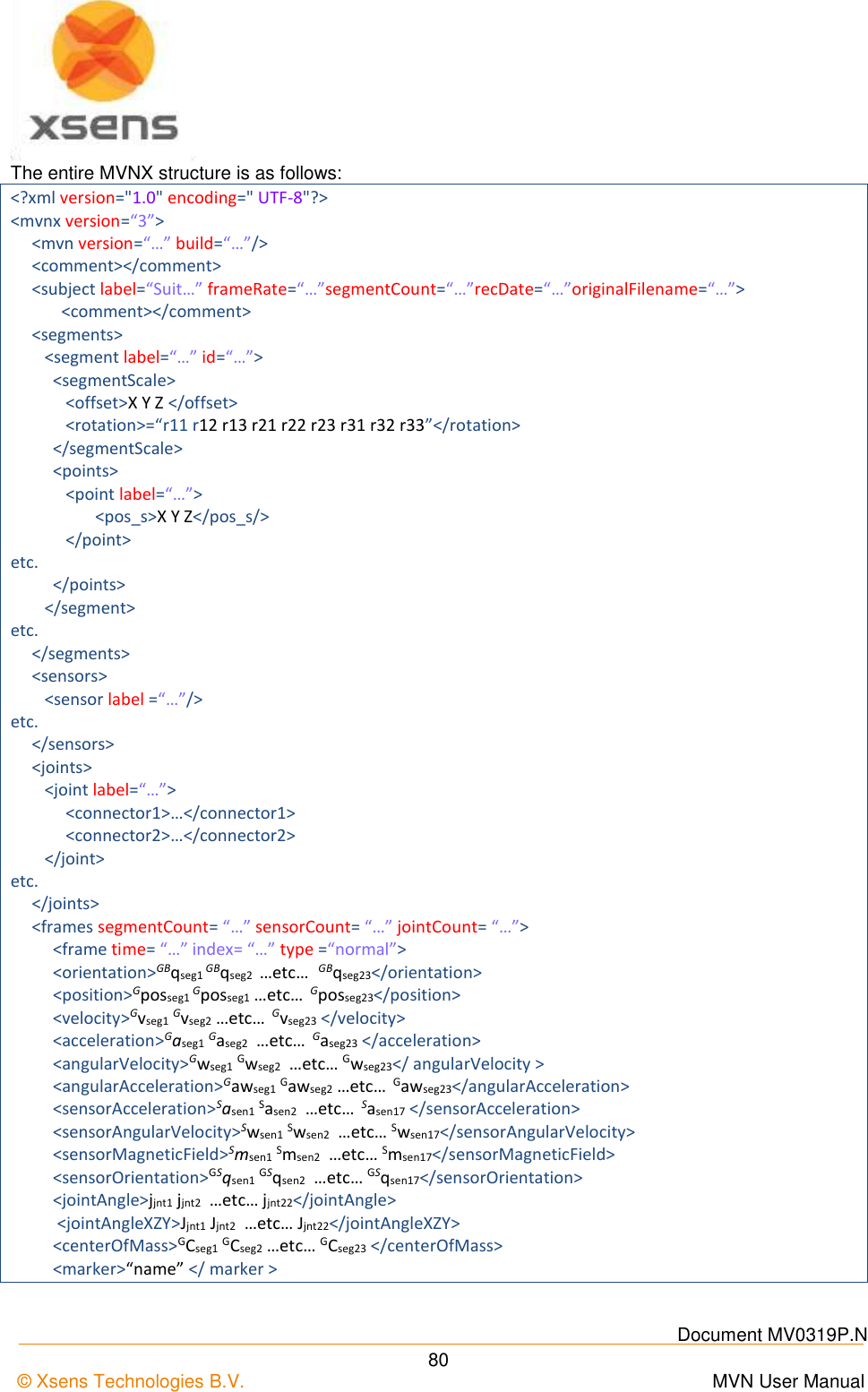
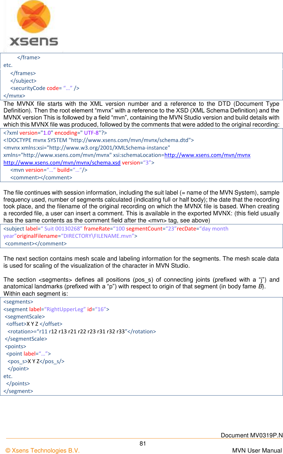
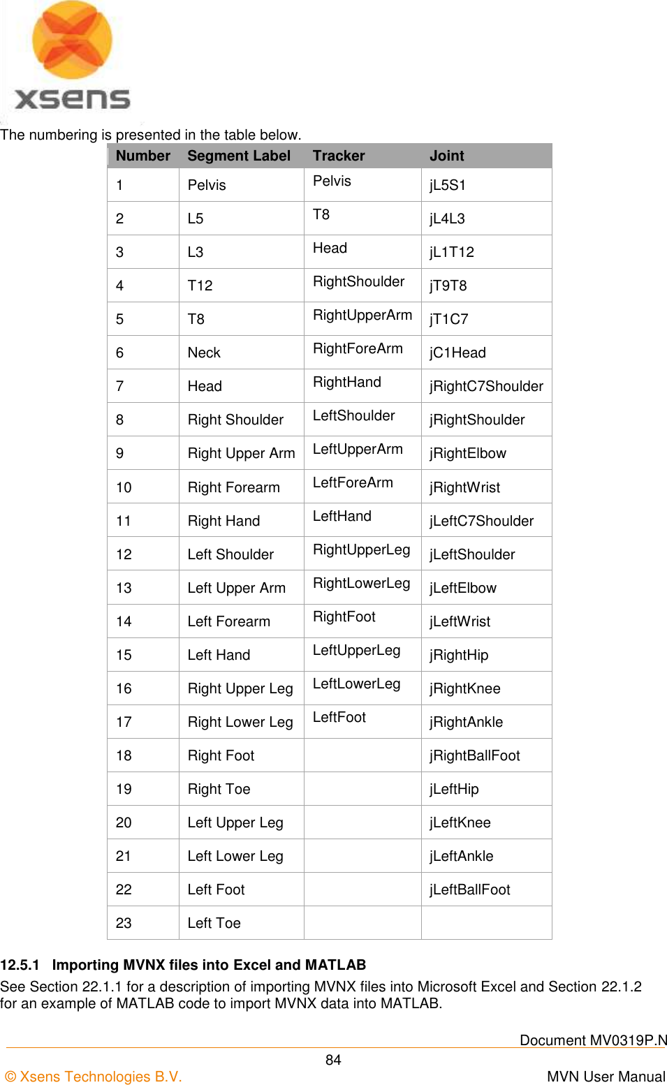
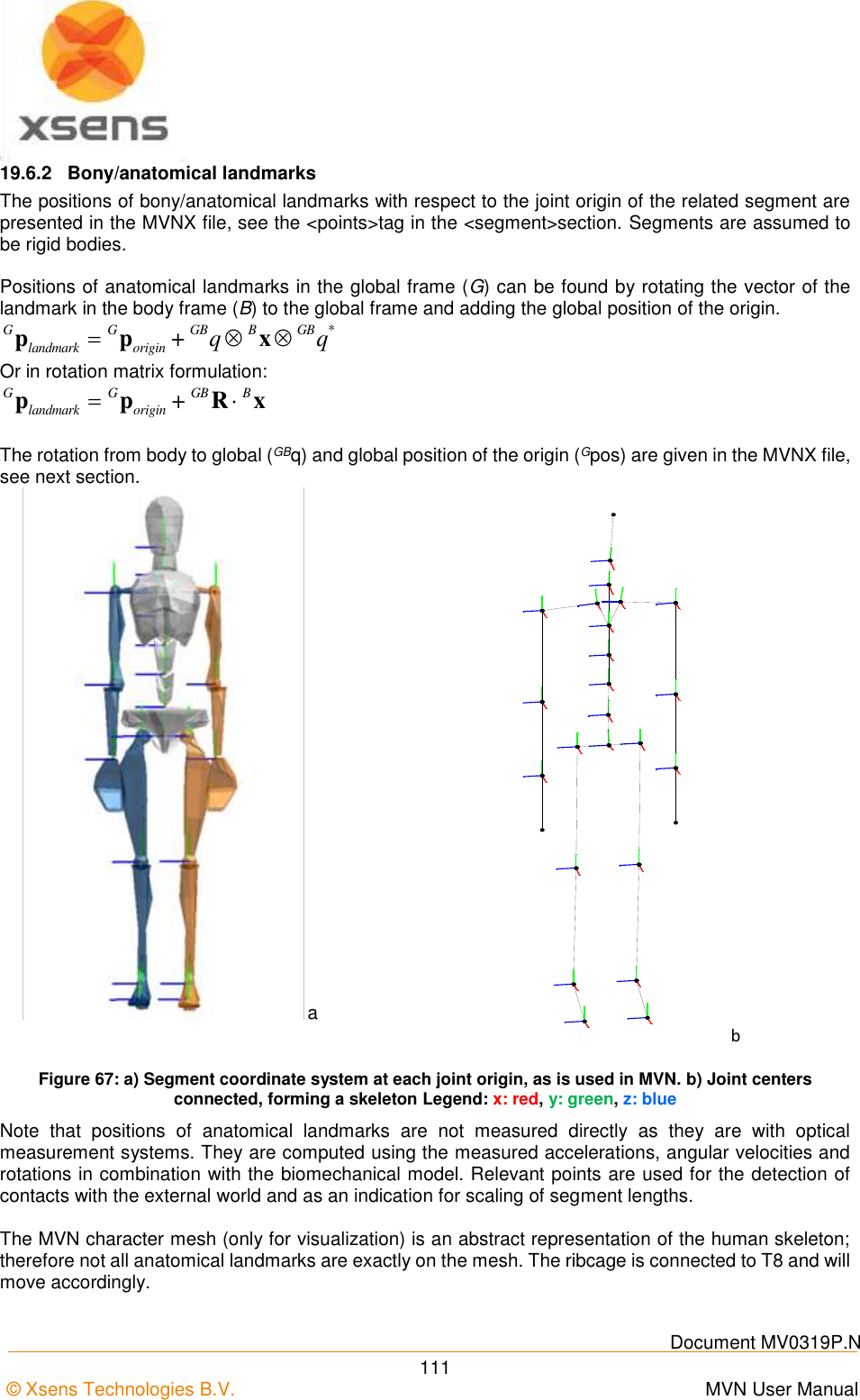
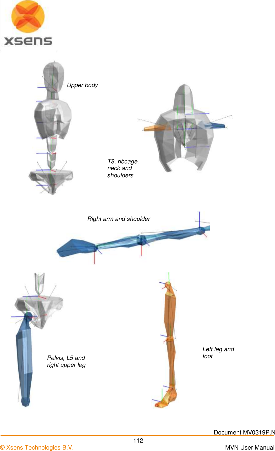
![Document MV0319P.N © Xsens Technologies B.V. MVN User Manual 82 The sensor data is simply a list of the names of segments measured with the MT’s: <sensors> < sensor label ="Pelvis"/> < sensor label ="Head"/> < sensor label ="RightShoulder"/> etc. </sensors> The “joints” section is a list of the names of joints contained and the segments and connections a given joint: <joints> <joint label=“ jLeftHip”> <connector1>Pelvis/jLeftHip </connector1> <connector2>LeftUpperLeg/jLeftHip </connector2> </joint> etc. </joints> The frames section is opened with the segment, sensor and joint count. The data of all parameters are contained within this section, including the calibration pose data. <frames segmentCount= “…” sensorCount= “…” jointCount= “…”> <frame … > </frame> Etc. </frames> The frame type “tpose” and “npose” sections describe the positions and rotations of all segments during respective calibration poses. All kinematic data is expressed in the global coordinate system: <frame time="0" index="-2" tc="00:00:00:00" ms="0" type="tpose"> <orientation>…<orientation/> <position>…<position/> </frame> Following this, the frames are split into time; each frame increment is equivalent to ([frame no. /update rate]*1000 [ms]). So at 120Hz, frame 1 is denoted by ([1/120]*1000) = 8.3[ms]. Frames measured during a normal session are denoted with type = “normal”. The index attribute still contains the original frame number. The optional “tc” and “ms” attributes contain the TimeCode values, i.e. the absolute real time at which that specific frame was recorded (often used to synchronize and combine this recording with other data that was gathered at the same time).](https://usermanual.wiki/Xsens-Technologies/AW-A2/User-Guide-2695618-Page-92.png)
![Document MV0319P.N © Xsens Technologies B.V. MVN User Manual 83 The selection in the preferences menu determines the MVNX contents. Orientation and Position are mandatory, all others are optional and may depend on the license. <frame time= “…” index="frame number" tc="15:57:47:02" ms="1418227067039" type =“normal”> <orientation>GBqseg1 GBqseg2 …etc… GBqseg23</orientation> <position>Gposseg1 Gposseg2 …etc… Gposseg23</position> <velocity>Gvseg1 Gvseg2 …etc… Gvseg23 </velocity> <acceleration>Gaseg1 Gaseg2 …etc… Gaseg23 </acceleration> <angularVelocity>Gwseg1 Gwseg2 …etc… Gwseg23</ angularVelocity > <angularAcceleration>Gawseg1 Gawseg2 …etc… Gawseg23</angularAcceleration> <sensorAcceleration>Sasen1 Sasen2 …etc… Sasen17 </sensorAcceleration> <sensorAngularVelocity>Swsen1 Swsen2 …etc… Swsen17</sensorAngularVelocity> <sensorMagneticField>Smsen1 Smsen2 …etc… Smsen17</sensorMagneticField> <sensorOrientation>GSqsen1 GSqsen2 …etc… GSqsen17</sensorOrientation> <jointAngle>jjnt1 jjnt2 …etc… jjnt22</jointAngle> <jointAngleXZY>Jjntx1 Jjntx2 …etc… Jjntx22</jointAngleXZY> <centerOfMass>GCseg1 GCseg2 …etc… GCseg23 </centerOfMass> <marker>“name” </ marker name> </frame> For the elements represented below with a subscript “seg”, the set will contain the number of segments (segmentCount) times the number of columns of data. For a full body, this is 23 segments. Subscript “sen” contains the number of MT’s (sensorCount) times the number of columns of data. For a full body, this is 17. Subscript “jnt” contains the number of joints (jointCount) times the number of columns of data. For a full body, this is 22 joints. GBqseg 1x4 quaternion vector (q0, q1, q2, q3) describing the orientation of the segment in the global frame. Gposseg 1x3 position vector (x, y, z) of the origin of the segment in the global frame in [m]. Gvseg 1x3 velocity vector (x, y, z) of the origin of the segment in the global frame in [m/s]. Gaseg 1x3 acceleration vector (x, y, z) of the origin of the segment in the global frame in [m/s2]. Gwseg 1x3 angular velocity vector (x, y, z) of the segment in the global frame in [rad/s]. Gawseg 1x3 angular acceleration vector (x, y, z) of the origin of the segment in the global frame in [rad/s2]. Sasen 1x3 sensor acceleration vector (x, y, z) of the sensor in [acc/s2]. Swsen 1x3 sensor angular velocity vector (x, y, z) of the sensor in [rad/s]. Smsen 1x3 sensor magnetic field vector (x, y, z) of the sensor in [a.u.]. GSqsen 1x4 sensor orientation quaternion (q0, q1, q2, q3) of the sensor in the global frame in. jjnt 1x3 Euler representation of the joint angle vector (x, y, z) in [deg], calculated using the Euler sequence ZXY. Jjntx 1x3 Euler representation of the joint angle vector (x, y, z) in [deg], calculated using the Euler sequence XZY. Note: The joint angle using Euler sequence XZY is calculated and exported for all joints, but commonly only used for the shoulder joints, and it may depend on the movement of the shoulder if it is appropriate to use. GCseg 1x3 position of the body Center of Mass (x,y,z) in the global frame in [m].](https://usermanual.wiki/Xsens-Technologies/AW-A2/User-Guide-2695618-Page-93.png)


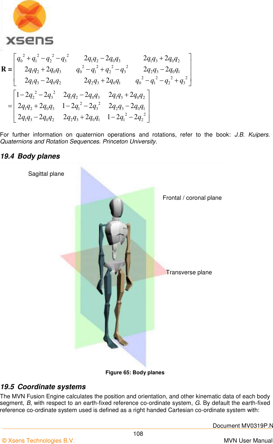
![Document MV0319P.N © Xsens Technologies B.V. MVN User Manual 110 Figure 66: Global and local coordinate frames in MVN Studio 19.6 Anatomical model 19.6.1 Definition of segment axes To describe motion capture data in clinically meaningful data, e.g. joint rotations, it is necessary to define a coordinate reference frame attached to the body segment. The ISB proposal for standardization for joint coordinate systems is currently based on positions (optical markers) of bony landmarks. For most segments on the body, the origin of the reference frame and direction of axes are described in Wu and Cavanagh (1995) [i] Wu et al. (2002) [ii] and Wu et al. (2005) [iii].The MVN Fusion Engine uses the calibration poses to determine the direction of the axes of each segment. Figure 67a shows the origins of the segment axes in the neutral anatomical pose. The origin of the segment is always in the proximal joint center which is the functional rotation point. The origin is chosen such that by connecting all joint centers a character (skeleton) is formed, see Figure 67b. Their positions for the calibration poses in the global reference frame can be found in the <segments>section and <frame type=”tpose/npose”>when exporting as MVNX file. Segment A Segment B Sensor BYA BXA BZA BXB BYC BZB SXA SYA Body frame Sensor frame GZ GX GY Global frame](https://usermanual.wiki/Xsens-Technologies/AW-A2/User-Guide-2695618-Page-120.png)
![Document MV0319P.N © Xsens Technologies B.V. MVN User Manual 114 19.7 Segment axes definitions and Origin Definitions Note: To ease comparison between the MVN segment co-ordinate systems with the International Society of Biomechanics recommendation, currently based on optical position tracking systems, the ISB recommendation is presented next to the MVN definition. The MVN segment axes definition and origins have been chosen as closely as possible to the ISB recommendation where whenever possible. MVN ISB [ii] O Midpoint between right and left hip center of rotation Coincident with hip center of rotation X Perpendicular to Y and Z Pointing forward Line parallel to a line lying in the plane defined by two ASISs and midpoint of two PSIS, orthogonal to Z-axis. Pointing anteriorly. Y hipOrigin to jL5S1 Pointing up Line perp. to X and Z. Pointing cranially. (Della Croce et al.[iv]) Z to jLeftHip to jRightHip Pointing right Line parallel to a line connecting right and left ASISs. Pointing right. NB: Della Croce et al. [iv] define O as the midpoint between RASIS and LASIS 19.7.1 Spinal segments: L5, L3, T12, T8: Segments 2-5 MVN ISB [ii] O jL5S1, jL4L3, jL1T12, jT9T8 X Pointing forward Line per. Y and Z Y Joint to Joint Pointing up Line passing thru centers of vertebra’s upper and lower endplates Z Perp. to X and Y Pointing right Line parallel to a line joining similar landmarks on the bases and right and left pedicles Note: Spine segments not measured directly in MVN, they are interpolated between the MT’s of the Pelvis, Sternum and Head using a model of the spine. Joint origins are the rotation points in the vertebrae.](https://usermanual.wiki/Xsens-Technologies/AW-A2/User-Guide-2695618-Page-124.png)
![Document MV0319P.N © Xsens Technologies B.V. MVN User Manual 115 19.7.2 Neck: Segment 6 MVN ISB O jT1C7 Not described in ISB X Perp. to Y and Z Pointing forward Y jT1C7 to jC1Head Z Pointing right Note: The neck segment is not measured directly in MVN; it is calculated using a model of the neck. 19.7.3 Head: Segment 7 MVN ISB O jC1Head Not described in ISB X Perp. to Y and Z Y jC1Head to TopOfHead Z Left Ear to Right Ear Note: Position of Ears are not measured but assumed to be on the same height. 19.7.4 Shoulder: Segment 8 Right and Segment 12 Left MVN ISB O jRightC7Shoulder jLeftC7Shoulder See Wu et al. [iii] and Šenk et al.v for range of definitions. X Pointing forward Y Perp. to X and Z Z Right: jRightC7Shoulder to jRightShoulder to Left: jLeftC7Shoulder to jLeftC7 In ISB the shoulder complex is described with the Thorax, Clavicle, Scapula and Humerus. MVN does not define the thorax segment. The thorax region is split into spine segments. The mesh of the thorax](https://usermanual.wiki/Xsens-Technologies/AW-A2/User-Guide-2695618-Page-125.png)
![Document MV0319P.N © Xsens Technologies B.V. MVN User Manual 116 will move with segment T8 which is measured with the MT of the sternum. MVN does not measure the clavicle and is undefined in MVN. 19.7.5 Upper Arm (Humerus): Segment 9 Right and Segment 13 Left There are two segment coordinate systems described in ISB. The system described below is option 1. MVN ISB [iii] O jRightUpperArm GH jLeftUpperArm GH GH X Sagittal plane Pointing forward Line perp. Plane EL-EM-GH Pointing forward Y Right: jRightElbow to jRightShoulder Left: jLeftElbow to jLeftShoulder Line connecting GH to mid point EL-EM Pointing to GH Z Perp. to X and Y Pointing to the right Line perp. Y and Z Pointing to the right 19.7.6 Forearm (Radius/Ulna): Segment 10 Right and Segment 14 Left There are two segment coordinate system described in ISB. Option 1 is described here. MVN ISB [iii] O jRightElbow jLeftElbow US X Pointing forward Line Perp. plane thru US-RS and midpoint EL-EM Pointing forward Y Right: jRightWrist to jRightElbow Left: jLeftWrist to jLeftElbow Line connecting GH to mid point EL-EM Z Perp. to X and Y Pointing right Line perp. X and Y Note: The joint origin is the midpoint between the epicondyles in MVN. In the anatomical pose, the hand and forearm are orientated forward](https://usermanual.wiki/Xsens-Technologies/AW-A2/User-Guide-2695618-Page-126.png)
![Document MV0319P.N © Xsens Technologies B.V. MVN User Manual 117 19.7.7 Hand: Segment 11 Right and Segment 15 Left MVN ISB [iii] O jRightWrist jLeftWrist ISB defines origins and axes for each: Of the 5 Metacarpals 14 phalanges X Pointing forward Y Top of Hand to jRightWrist/jLeftWrist Pointing Vertical Z Perp. to X and Y Pointing right Note: In MVN, the joint center is the midpoint between the styloids. No metacarpals are measured in MVN. This description is for the anatomical pose. When the subject stands in the N-pose, X will no longer point anteriorly, but medially. 19.7.8 Upper Leg (Femur): Segment 16 Right and Segment 20 Left MVN ISB [ii] O jRightHip/jLeftHip (Only defined for use of calculating the hip joint angle): Coincident with right (or left) hip center of rotation, coincident with pelvic center O in neutral configuration X Perpendicular to Y and Z Pointing forward in sagittal plane Line perp. to Y- and x- Pointing anteriorly. (Della Croce et al. [iv]) Y Right: jRightKnee to jRightHip Left: jLeftKnee to jLeftHip Line joining midpoint between medial and lateral Fes and the origin. Pointing cranially Z Right: Medial to Lateral Left: Lateral to Medial Pointing right Line perp. to Y-axis lying in plane defined by origin and two Fes. Pointing Right.](https://usermanual.wiki/Xsens-Technologies/AW-A2/User-Guide-2695618-Page-127.png)
![Document MV0319P.N © Xsens Technologies B.V. MVN User Manual 118 Note: In ISB and MVN, the origin is in center of hip rotation, which is the head of the femur. Della Croce [iv]: midpoint LE and ME. In the MVN model, the lateral and medial epicondyles are on the same height. 19.7.9 Lower Leg (Tibia/Fibula): Segment 17 Right and Segment 21 Left MVN ISB [ii] O jRightKnee jLeftKnee IM IM X Perp. Y and Z Pointing forwards Line perp. to torsional plane of tibia/fibula. Pointing anteriorly Y Right: jRightAnkle to jRightKnee Left: jLeftAnkle to jLeftKnee Line perp. to X and Z Z Right: Medial to Lateral Left: Lateral to Medial Pointing right Line between MM and LM. Pointing to the right Note: In MVN, the joint center is approx. between LC and MC which corresponds with the center of rotation of the lower leg. Same coordinate system as Della Croce [iv], except that the origin is not in IM. In ISB, the Y axis is not along the Tibia. In the MVN model the lateral and medial epicondyles and lateral and medial malleoli are the same height.](https://usermanual.wiki/Xsens-Technologies/AW-A2/User-Guide-2695618-Page-128.png)
![Document MV0319P.N © Xsens Technologies B.V. MVN User Manual 119 19.7.10 Foot (Calcaneus): Segment 18 Right and Segment 22 Left MVN ISB [ii] O jRightAnkle jLeftAnkle IM IM X Sagittal plane forward Line perp. to frontal plane of tib/fib in neutral configuration. Pointing anteriorly. Y Vertical (aligned with gravity, pointing up) Line coincident with long axis of tibia/fibula, in neutral configuration. Pointing cranially Z Perp. to X and Y Pointing right Line perp. to x- and Y- Note: In the MVN model lateral and medial malleoli are on the same height. 19.7.11 Toe: Segment 19 Right and Segment 23 Left The toes are not defined in ISB. MVN ISB O jRightToe jLeftToe The toes are not defined in ISB. X Sagittal plane forward Y Vertical (aligned with gravity) Z Perp. to X and Y Note: In MVN toes are not measured directly but are based on the foot kinematics and contact detection. The origin is between the metatarsals of the foot. Toes can only flex and extend, other kinematics are due to interpolation. 19.8 Joint angles Typically, a joint rotation is defined as the orientation of a distal segment BGB qwith respect to a proximal segment : A B A BB B GB GB*q= q q where denotes a quaternion multiplication and *the complex conjugate of the quaternion (see Section 19.3.1). There are a few commonly used parameterizations of the joint rotation ABBBq that describe joint angles: the Cardan/Euler representation [Cole 1993, Woltring 1994] joint coordinate system [Grood & Suntay 1983]vi helical angle [Kinzel 1972] AGB q](https://usermanual.wiki/Xsens-Technologies/AW-A2/User-Guide-2695618-Page-129.png)
![Document MV0319P.N © Xsens Technologies B.V. MVN User Manual 120 Note that all representations of the joint angles are based on the same quaternion or rotation matrix. The differences lie only in how the angles are extracted (represented) from this rotation. The International Society of Biomechanics (ISB) has proposed standards for rotation sequences for the lower [Wu et al, 2002ii] and upper body [Wu et al 2005iii]. 19.8.1 Euler Extractions for the joint angles In order to produce validated joint angle output, Xsens MVN works closely to the ISB and Grood and Suntay recommendations [i,ii,iii,vi]. Almost all angles follow the ISB Euler angle extractions of Z (flexion/extension), X (abduction/adduction) Y (internal/external rotation). The definitions of the origins of the segments are somewhat different, since MVN uses MT’s placed on the segment, rather than markers placed on bony landmarks. The origins and coordination axes are defined above. 19.8.2 Shoulder angle definitions For joint angle calculations, the only difference for Euler extractions between MVN and ISB is for the shoulder joint. MVN provides three different shoulder angle calculations, as can be seen in the data tree, after a session has been recorded. The shoulder joint angles provided are: Angles between C7 and the shoulder segment Euler rotation sequence ZXY Euler rotation sequence XZY](https://usermanual.wiki/Xsens-Technologies/AW-A2/User-Guide-2695618-Page-130.png)
![Document MV0319P.N © Xsens Technologies B.V. MVN User Manual 139 22.1.2 Import to MATLAB Import MVNX files using the MATLAB files in the MATLAB Installer of MVN Studio. Below is a copy of the information stored in “main_mvnx.m”. This file intended simply as an example. The user is expected to expand upon this for their own use, depending on data they have exported to mvnx. The example code contains: main_mvnx.m and load_mvnx.m. The file main_mvnx is detailed below. It calls the function load_mvnx.m, which is based on the MATLAB function for reading XML files. Example code to read the file: main_mvnx.m tree = load_mvnx(filename); % read some basic data from the file mvnxVersion = tree; fileComments = tree.subject.comment; %read some basic properties of the subject; frameRate = tree.subject.frameRate; suitLabel = tree.subject.label; originalFilename = tree.subject.originalFilename; recDate = tree.subject.recDate; segmentCount = tree.subject.segmentCount; %retrieve sensor labels %creates a struct with sensor data sensorData = tree.subject.sensors.sensor; %retrieve segment labels %creates a struct with segment definitions segmentData = tree.subject.segments.segment; %retrieve the data frames from the subject nSamples = length(tree.subject.frames.frame); %pre allocate %pre allocate some memory for the position of Segment1 p_Segment1 = zeros(nSamples,3); %read the data from the structure e.g. segment 1 for i=[1:nSamples] p_Segment1(i,:)=tree.subject.frames.frame(i).position(1:3); end %Plot plot(p_Segment1) figure plot3(p_Segment1(:,1),p_Segment1(:,2),p_Segment1(:,3));](https://usermanual.wiki/Xsens-Technologies/AW-A2/User-Guide-2695618-Page-149.png)
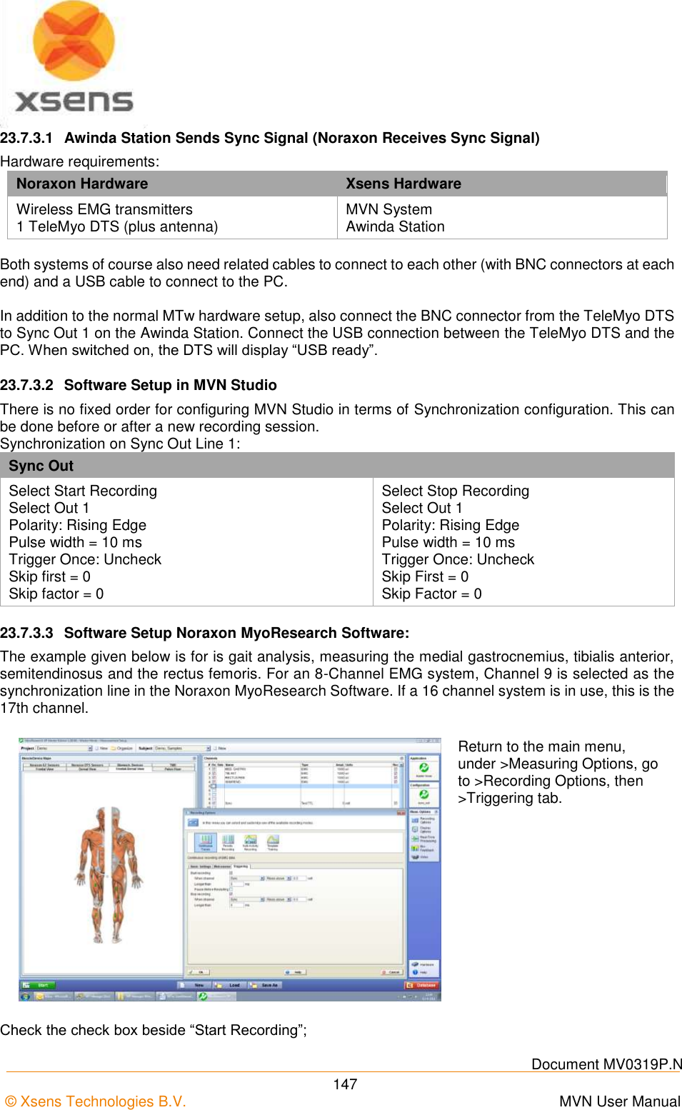
![Document MV0319P.N © Xsens Technologies B.V. MVN User Manual 142 23.3 Sync Out Sync Out is the command that enables the Xsens system to send a trigger pulse for synchronization purposes. A control signal is sent via the Awinda/Sync Station, from MVN Studio to the third party hardware. Sync Type Description Start Recording Upon clicking the record button in MVN Studio, the Awinda Station starts the recording and consequently sends a start recording trigger to the third party system. Stop Recording Upon clicking the record button in MVN Studio, the Awinda Station stops recording and sends a stop recording trigger to the third party system. Go to Operational The default polarity of the output line is always low. However, for input triggers that assume high polarity, the polarity of the line must be set high beforehand. This becomes possible, using 'Go to operational'. When ‘Go to Operational’ is selected on the same line as the assumed high polarity, the polarity is changed to high, preparing the system for sync. Interval Transition Measurement A frame / or interval transition at the Station can be used to give a signal to the external system, indicating the end of the strap-down integration interval over which data is calculated. Selecting this option, the frame transition is sent from the moment that “Start Measuring” is selected. Interval Transition Recording See Frame transition Measurement Selecting this option, the frame transition is sent from the moment that a recording is started. This is a very useful option to implement, to ensure that during a recording, the clocks of the synchronized systems are known, ensuring that any drift can be compensated for. A number of parameters can be set for each action: Parameter Description Sync Line The sync line to activate. Pulse Polarity Positive pulse (where the polarity is initially low [0V] and goes high [3.3V]). Negative pulse (where polarity is initially high [3.3V] and goes low [0V]). Trigger Once It is not advised to select Trigger once, if more than one recording using synchronization of multiple systems will be made. Skip First Number of initial sync pulses to skip. This command is useful if a well-defined delay is expected between the Xsens and the third party system. It may also be needed if the third party, like the Xsens system uses the same pulse properties to trigger different actions. See description provided above for Sync In. Skip Factor Number of sync pulses, between the sync pulses delivered, to skip. See Sync In Table description. Pulse Width Some systems wait for a signal of a minimum pulse width before generating the desired synchronization action. The Awinda / Sync Station can send a pulse with a duration of up to 99ms to a third party system. It is not recommended to send a signal longer than a frame width. Specify 0 ms to generate an infinite pulse width.](https://usermanual.wiki/Xsens-Technologies/AW-A2/User-Guide-2695618-Page-152.png)
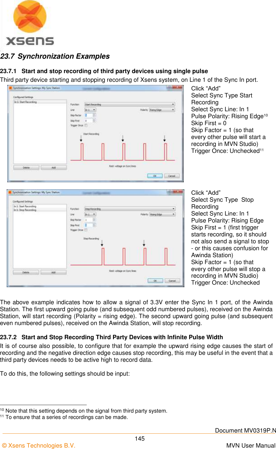
![Document MV0319P.N © Xsens Technologies B.V. MVN User Manual 146 Click “Add” Sync Type: Start Recording Sync Line: Out 1 Pulse Polarity: Rising Edge Pulse Width = 0µs12 Skip first = 0 Skip factor = 0 Trigger Once: Uncheck Click “Add” Sync Type: Stop Recording Sync Line: Out 1 Pulse Polarity: Falling Edge Pulse Width = 0µs[12] Skip first = 0 Skip factor = 0 Trigger Once: Uncheck Note: Stop recording time may not be on the last sample recorded. In any synchronization situation, there should only be one master. It is necessary to elect a master, either an Awinda Station, or a third party device. 23.7.3 Synchronizing with Noraxon EMG Synchronization was successfully tested between MT Manager, for the MTw Development Kit and Noraxon TeleMyo system. While we assume that the results will be just as successful with MVN, this has not yet been tested. The steps described below describe how to make it possible for the Awinda Station to send a synchronization signal (Xsens is Sync Out and Noraxon is Sync In) and how to receive the synchronization signal (Noraxon is Sync Out, Xsens Sync In). Of course, care must be taken when placing the EMG electrodes with the straps or suit of MVN. 12 Note that MVN Studio 4.1 use the unit microseconds for pulsewidth. For current users, all previous millisecond units used should be multiplied by 1000.](https://usermanual.wiki/Xsens-Technologies/AW-A2/User-Guide-2695618-Page-156.png)