Zebra Technologies LOS5000B Real Time Location Sensor User Manual Manual DRAFT
Zebra Technologies Corporation Real Time Location Sensor Manual DRAFT
UserManual.wiki
>
Zebra Technologies
>
LOS5000B User Manual
Manual DRAFT
Navigation menu
Upload a User Manual
Namespaces
Wiki Guide
HTML
PDF
Info
Views
User Manual
Discussion / Help
Navigation
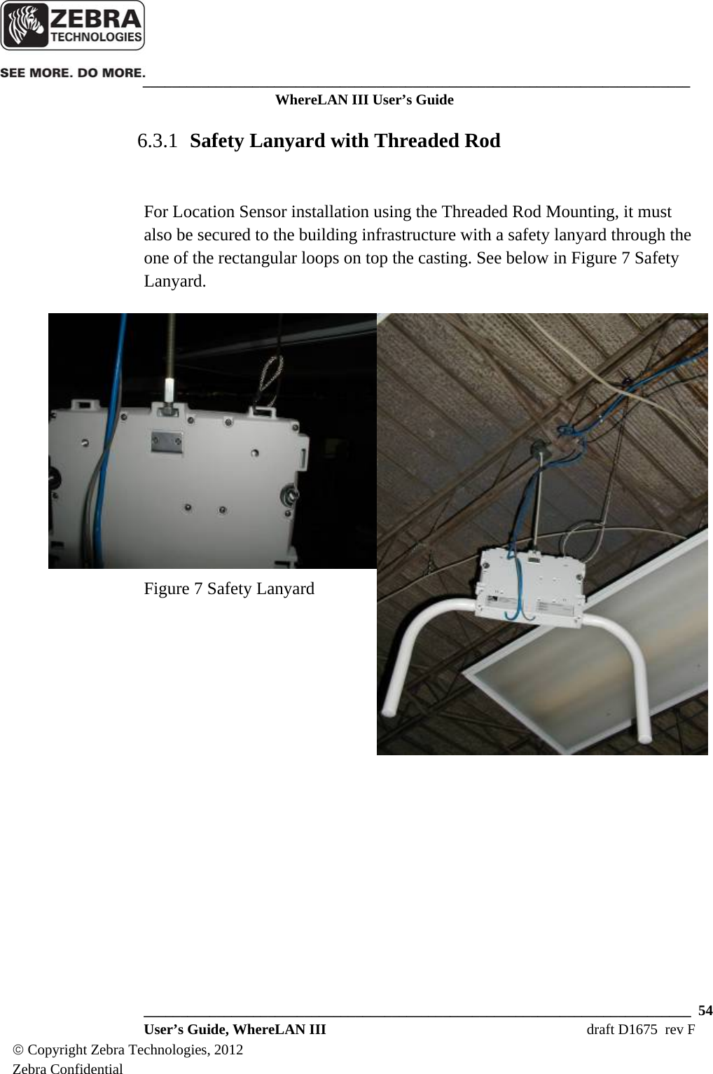
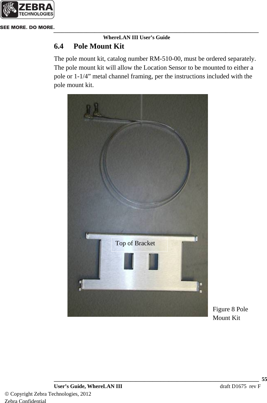
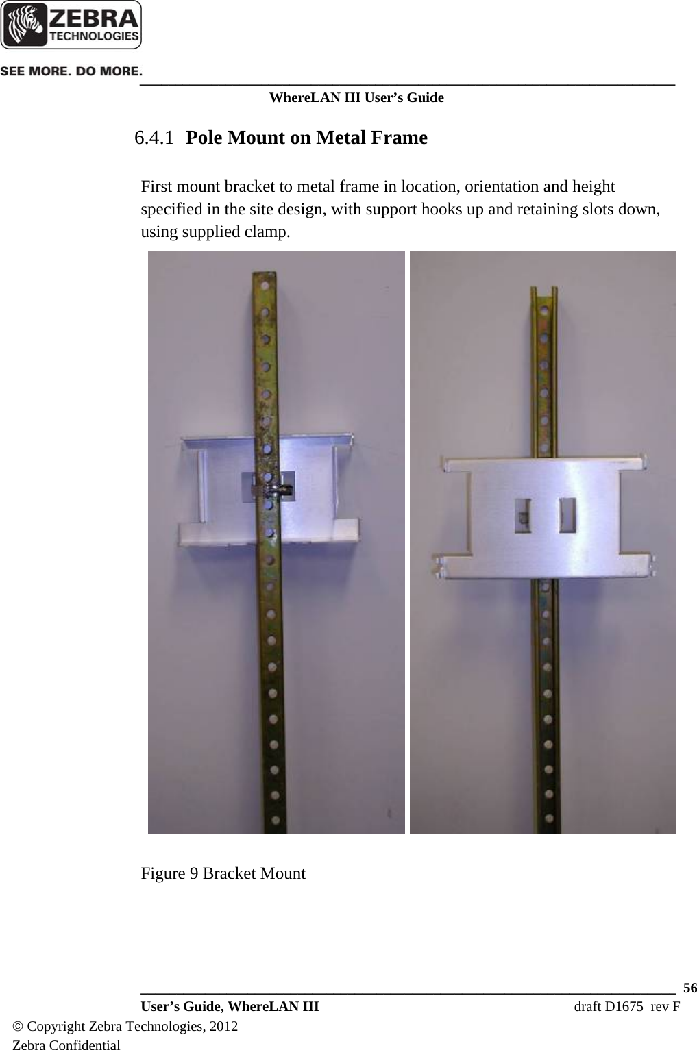
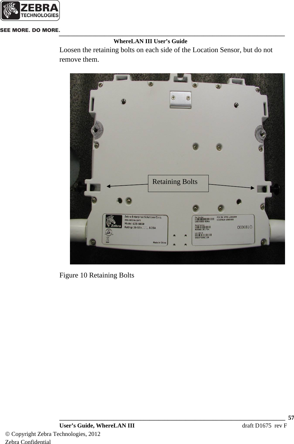
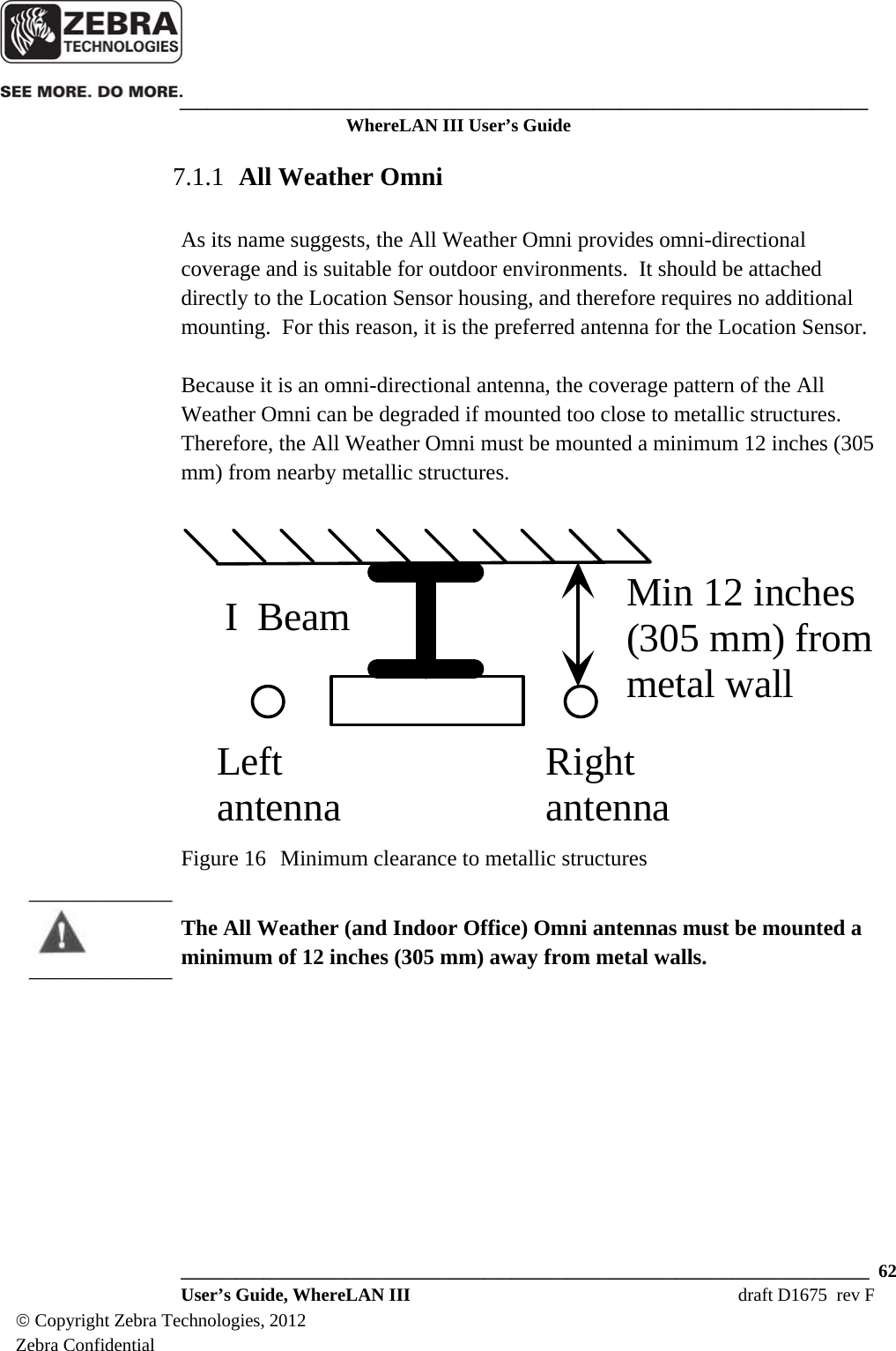
![___________________________________________________________________________ WhereLAN III User’s Guide ___________________________________________________________________________ 89 User’s Guide, WhereLAN III draft D1675 rev F © Copyright Zebra Technologies, 2012 Zebra Confidential APPENDIX A: LOS-5000 EFFECTIVE PROJECTED AREA (EPA) LOS Housing • Housing Size (Inches) [cm]: 12.0” [30.4] Wide, 10.3” High [26.2], 1.7” [4.3] Deep • Housing Size with 1/2" Radial Ice (Inches) [cm]: 12.5” [31.8] Wide, 10.8” High [27.4], 2.3” [5.8] Deep • Maximum Projected Area with Ice (Square Inches): 135.0” [2212 cc] • Shape Factor (CD per EIA-222-F) 1.4 • Effective Projected Area with Ice (Square Inches) 189 [3097cc] Omni Antenna (One Antenna) • Antenna Size (Inches) [cm]: 1.3 [3.3] Diameter 19.0 [302] Long • Antenna Size with 1/2" Radial Ice (Inches): 2.3 [5.8] Diameter 20.0 [50.8] Long • Maximum Projected Area with Ice (Square Inches): 46.6 [763cc] • Shape Factor (CD per EIA-222-F) 0.8 • Effective Projected Area with Ice (Square Inches) 37.3 [611cc] LOS-5000 Effective Projected Area (EPA) • LOS Housing with Ice (Inches): 189 [3097cc] • Omni Antenna #1 with Ice (Inches): 37.3 [611cc] • Omni Antenna #2 with Ice (Inches): 37.3 [611cc] • Total Effective Projected Area with 0.5 inch Radial Ice Effective Projected Area, Total (Square Inches): 263.6 [4319cc] Note: The above does not include conduit/cabling for Omni Antenna polarization diversity and LOS-5000 power](https://usermanual.wiki/Zebra-Technologies/LOS5000B/User-Guide-2281055-Page-89.png)
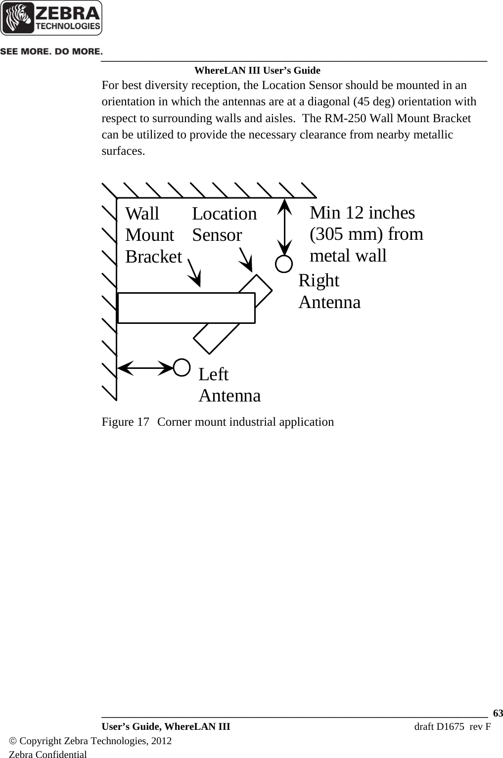
![___________________________________________________________________________ WhereLAN III User’s Guide ___________________________________________________________________________ 90 User’s Guide, WhereLAN III draft D1675 rev F © Copyright Zebra Technologies, 2012 Zebra Confidential APPENDIX B: LOS-5000 WEIGHT LOS-5000 Housing • Housing Weight (Pounds): 7.0 [3.17.0Kg] • Ice Volume at 0.5 inch [12.7mm] Radial Thickness: 94.7 Cubic Inches [1552cc] • Assumed density of Ice: 0.032 pounds per cubic inch [0.90 g/cc] • Mass of Ice: 3.0 pounds [1.4Kg] • Housing and Ice Mass: 10.0 pounds [4.53Kg] Omni Antenna (One Antenna) • Antenna Weight: 0.8 pounds [0.36Kg] • Ice Volume at 0.5 inch [12.7mm] Radial Thickness: 58.9 Cubic inches [965 cc] • Assumed density of Ice: 0.032 pounds per cubic inch [0.90 g/cc] • Ice Weight: 1.9 pounds [.86Kg] • Antenna and Ice Weight: 2.7 pounds [1.22Kg) Total Weight with 1/2" Radial Ice • LOS Housing Ice: 10.0 pounds [4.53Kg] • Omni Antenna #1 with Ice: 2.7 pounds [1.22Kg] • Omni Antenna #1 with Ice: 2.7 pounds [1.22Kg] Weight, Total: 15.4 pounds [6.98Kg] Note: The above does not include conduit/cabling for Omni Antenna polarization diversity and LOS-5000 power](https://usermanual.wiki/Zebra-Technologies/LOS5000B/User-Guide-2281055-Page-90.png)
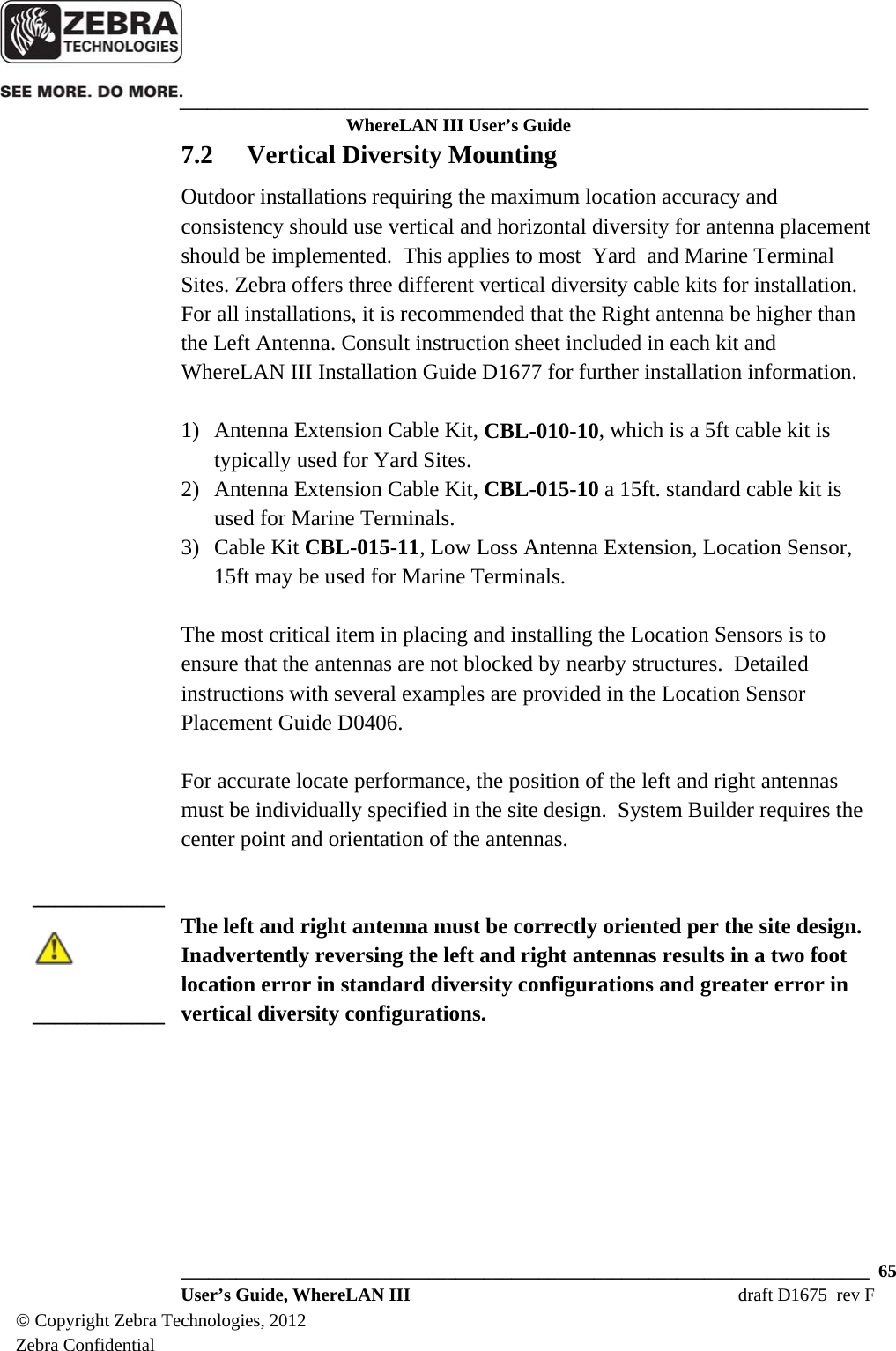
![___________________________________________________________________________ WhereLAN III User’s Guide ___________________________________________________________________________ 98 User’s Guide, WhereLAN III draft D1675 rev F © Copyright Zebra Technologies, 2012 Zebra Confidential APPENDIX E: HYPERTERMINAL BOOT SEQUENCE U-Boot 1.1.4 (May 6 2011 - 14:27:47) Micrel, WhereNet 1.2 DRAM: 32 MB Flash: 8 MB In: serial Out: serial Err: serial Enter "CTRL-Z" to abort autoboot in 3 seconds ## Booting image at 02020000 ... Image Name: Linux-2.6.9-KS8695 Image Type: ARM Linux Kernel Image (uncompressed) Data Size: 1441116 Bytes = 1.4 MB Load Address: 00008000 Entry Point: 00008000 Verifying Checksum ... OK OK ## Loading Ramdisk Image at 021a0000 ... Image Name: Ram disk Image Type: ARM Linux RAMDisk Image (gzip compressed) Data Size: 2124742 Bytes = 2 MB Load Address: 00800000 Entry Point: 00800000 Verifying Checksum ... OK Starting kernel ... Uncompressing Linux...................................................................................... done, booting the kernel. Linux version 2.6.9-KS8695 (gcc version 3.4.5) WhereNet Generation III CPU: ARM922Tid(wb) [41029220] revision 0 (ARMv4T) CPU: D VIVT write-back cache CPU: I cache: 8192 bytes, associativity 64, 32 byte lines, 4 sets CPU: D cache: 8192 bytes, associativity 64, 32 byte lines, 4 sets Machine: Micrel Centaur Memory policy: ECC disabled, Data cache writeback Built 1 zonelists Kernel command line: console=ttyAM0,19200 PID hash table entries: 256 (order: 8, 4096 bytes) Console: colour dummy device 80x30 Dentry cache hash table entries: 8192 (order: 3, 32768 bytes) Inode-cache hash table entries: 4096 (order: 2, 16384 bytes) Memory: 32MB = 32MB total Memory: 27488KB available (2205K code, 513K data, 68K init) Mount-cache hash table entries: 512 (order: 0, 4096 bytes) CPU: Testing write buffer coherency: ok](https://usermanual.wiki/Zebra-Technologies/LOS5000B/User-Guide-2281055-Page-98.png)