Zebra Technologies MC659B ENTERPRISE DIGITAL ASSISTANT (EDA) User Manual MC55 User Guide P N 72E 108859 02 Rev A
Zebra Technologies Corporation ENTERPRISE DIGITAL ASSISTANT (EDA) MC55 User Guide P N 72E 108859 02 Rev A
Contents
- 1. Users Manual 1
- 2. Users Manual 2
- 3. Users Manual 3
- 4. Users Manual 4
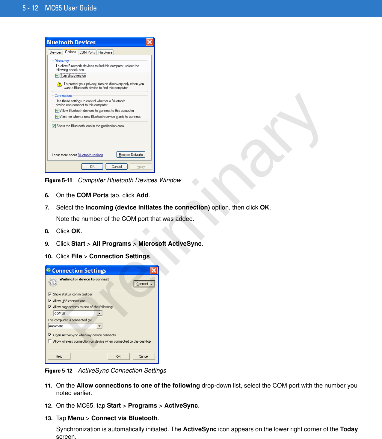
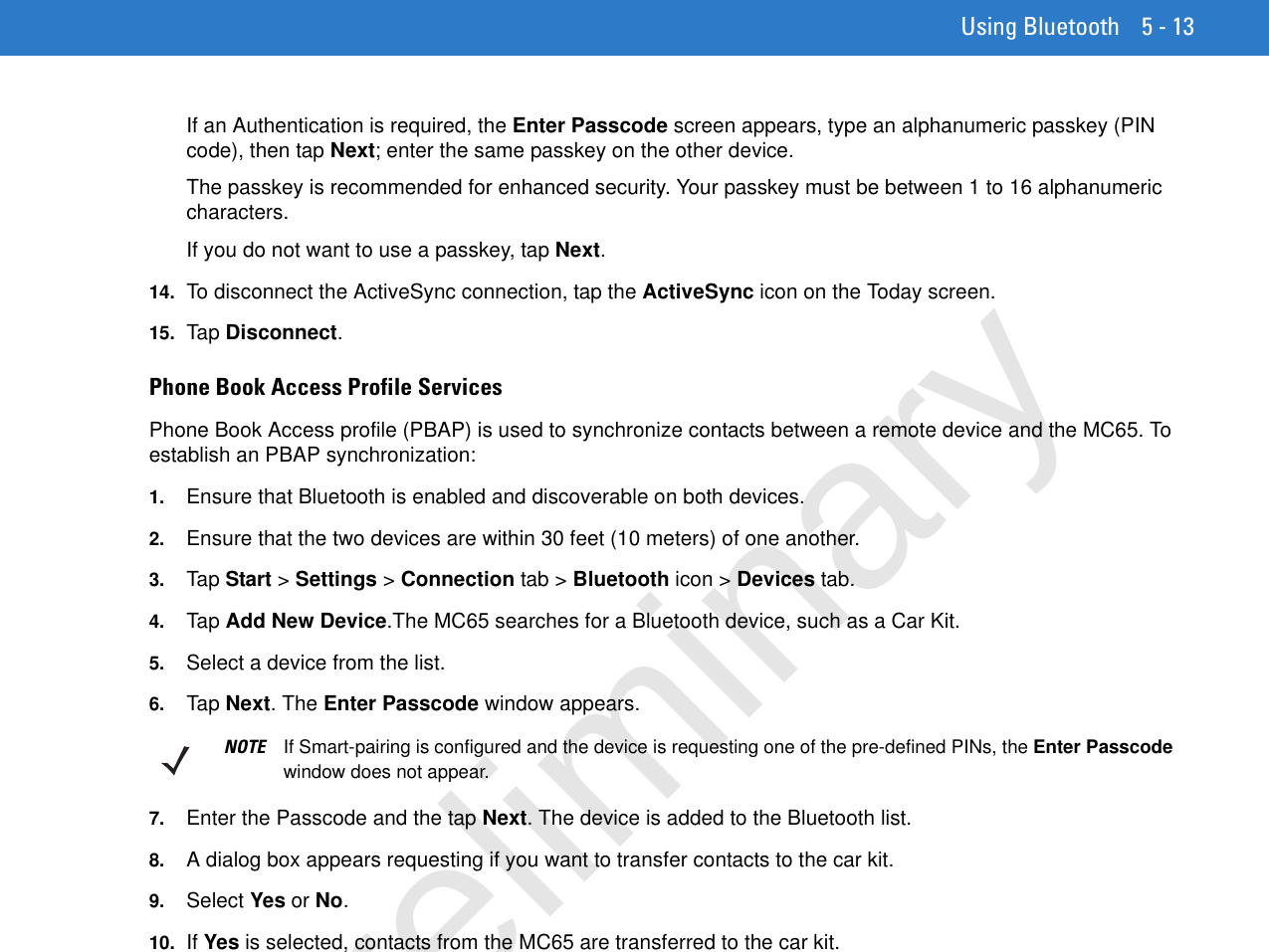
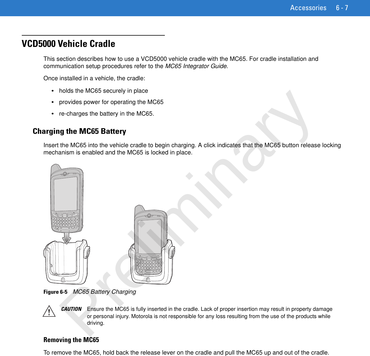
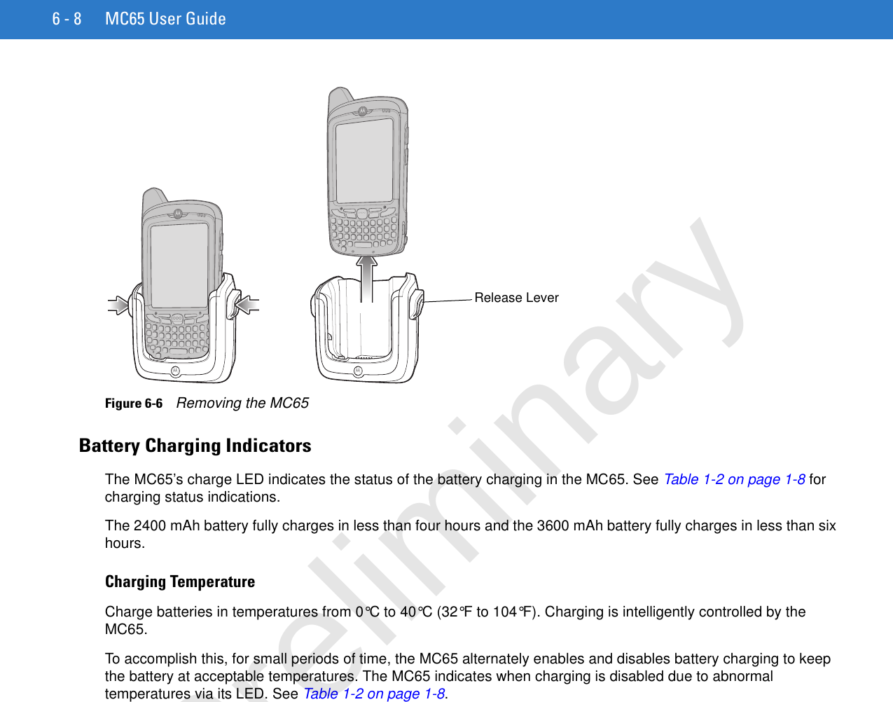
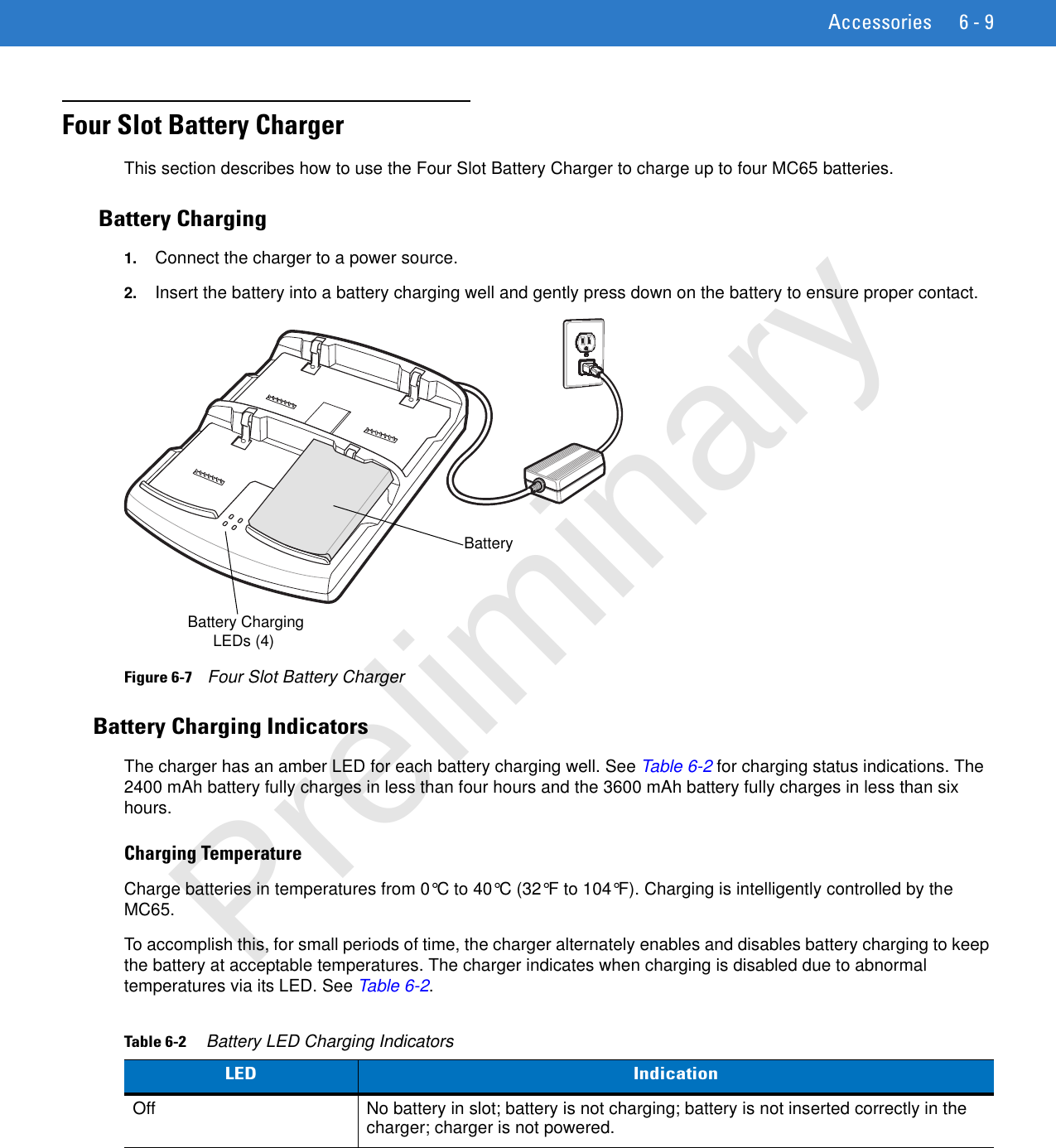
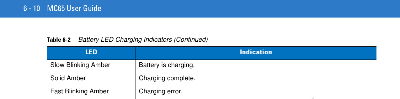
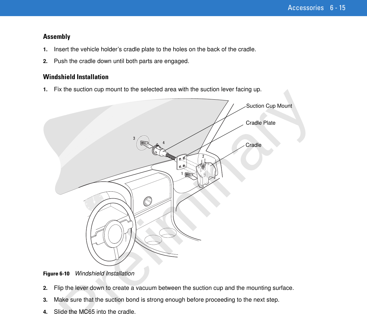
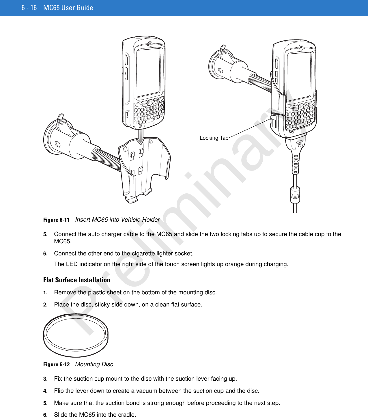
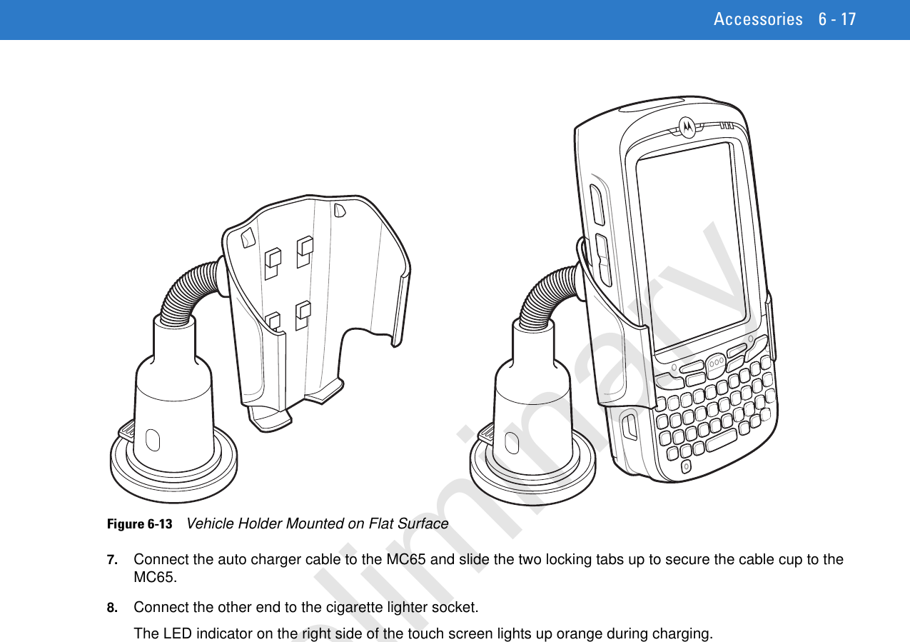
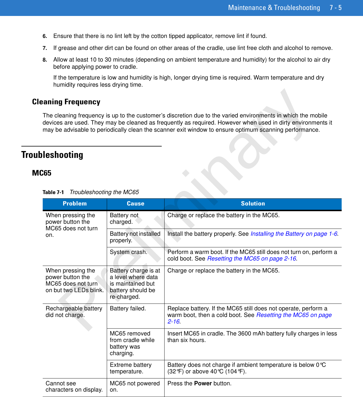
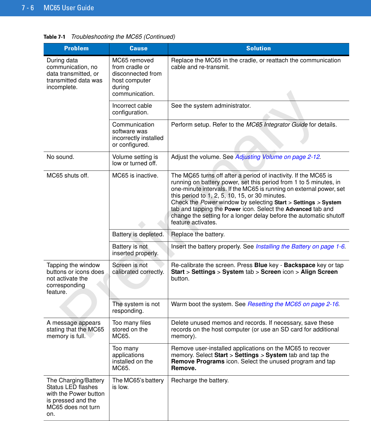
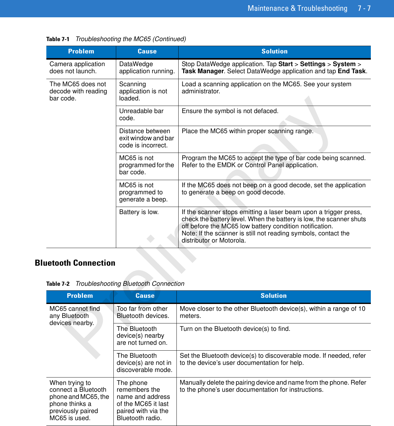
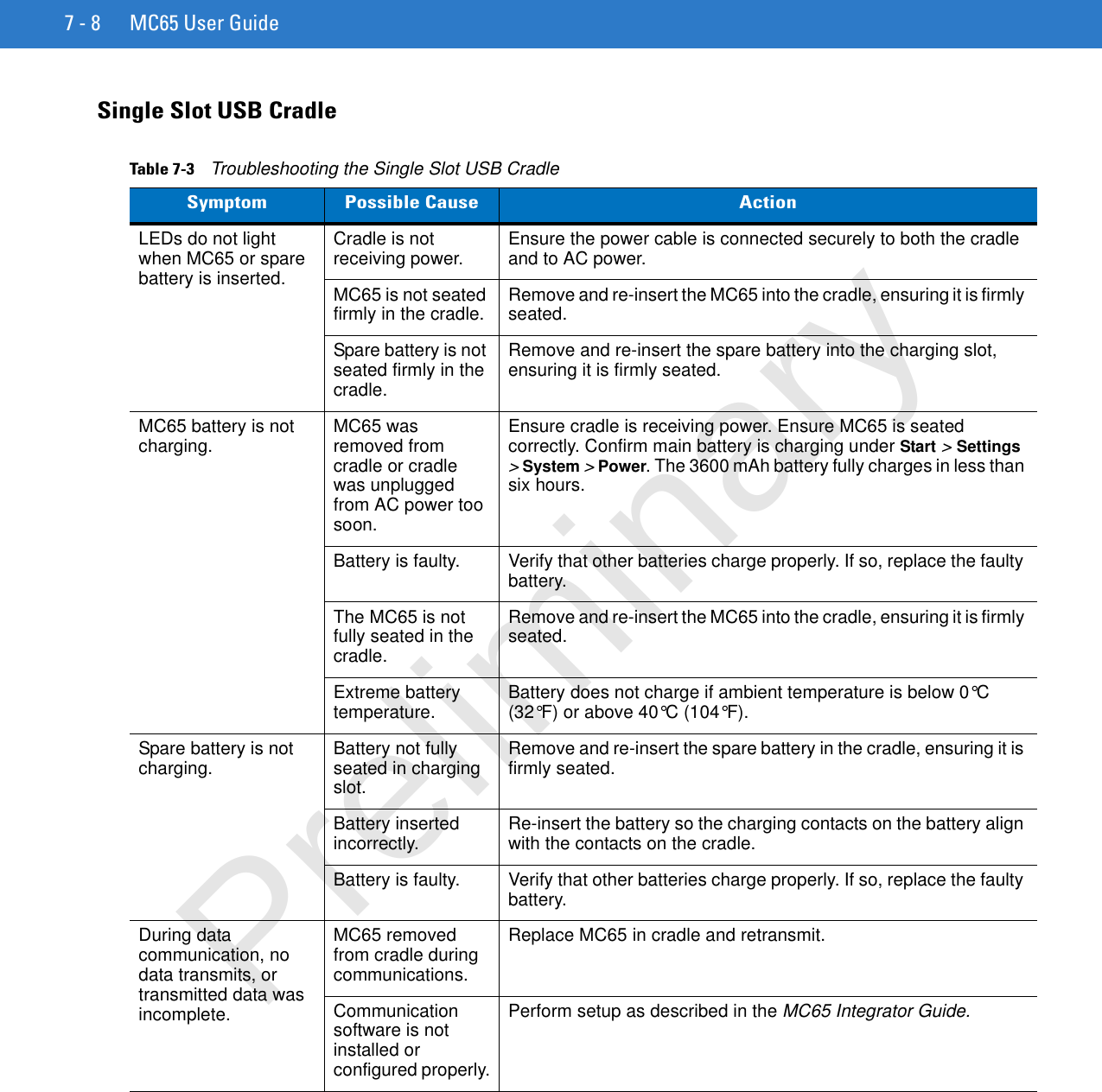
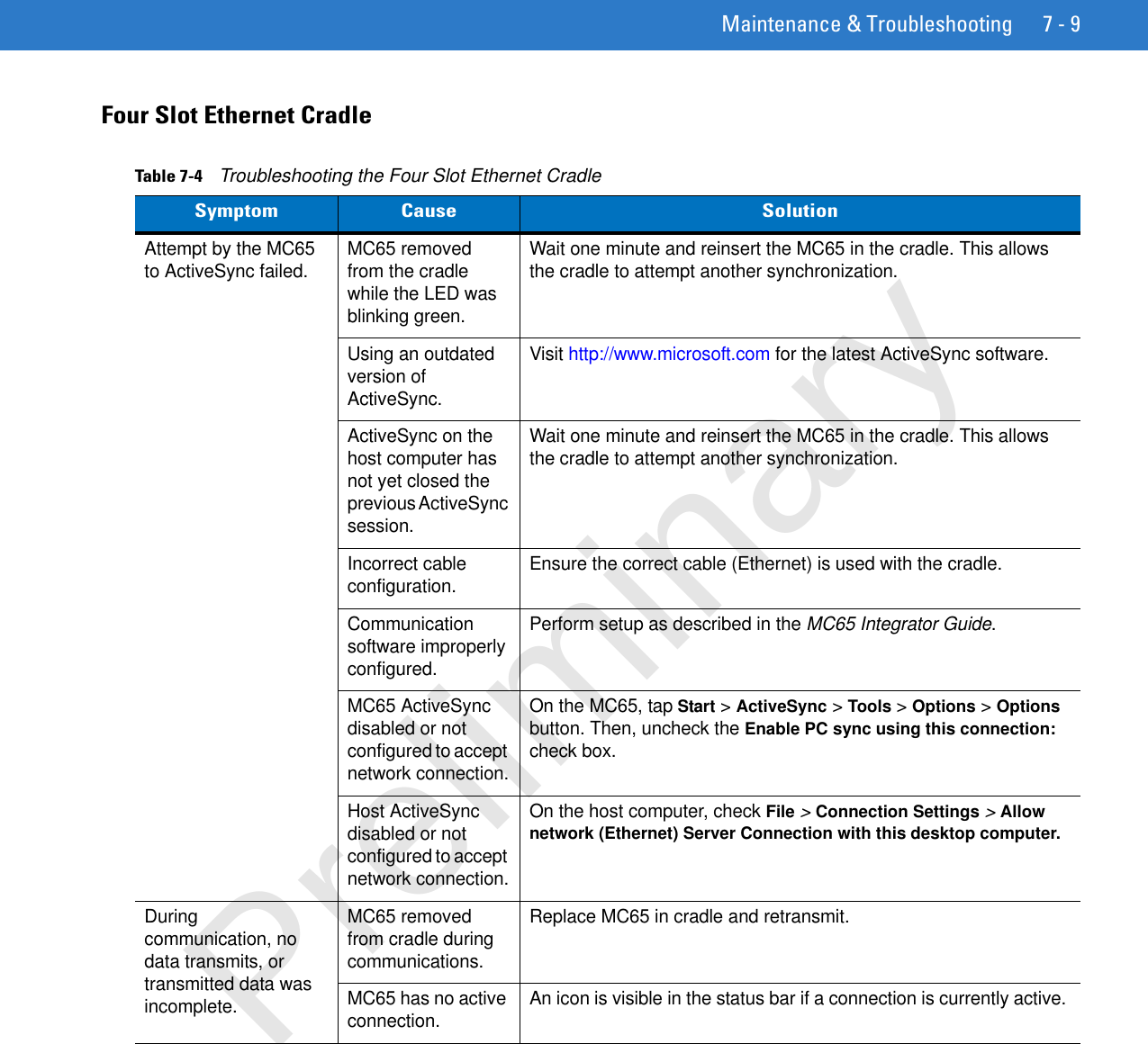
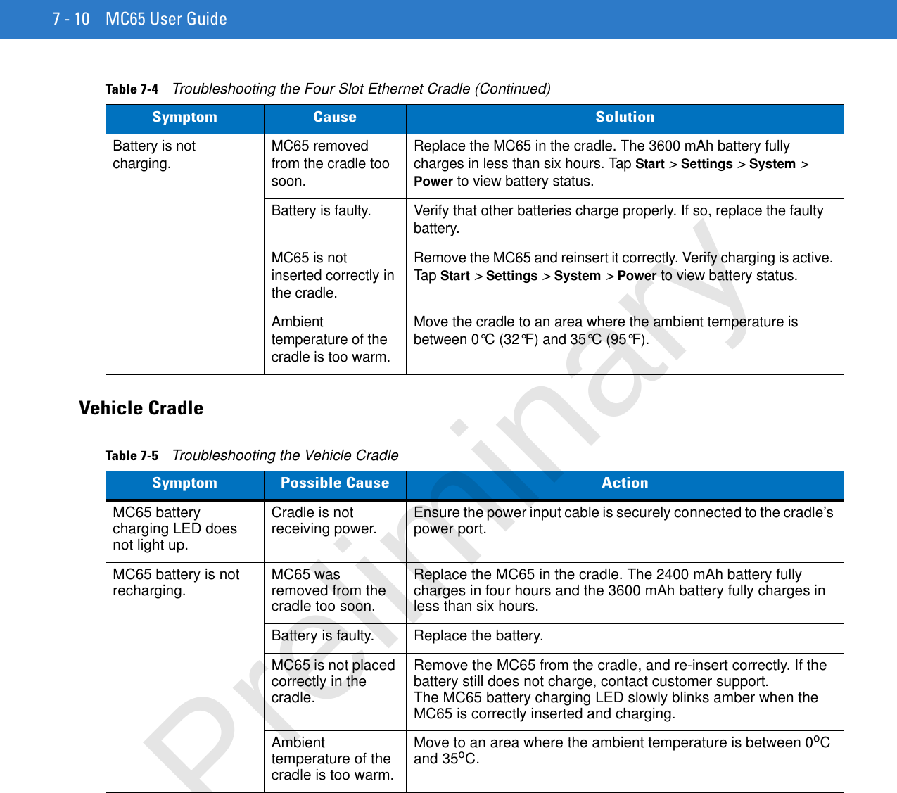
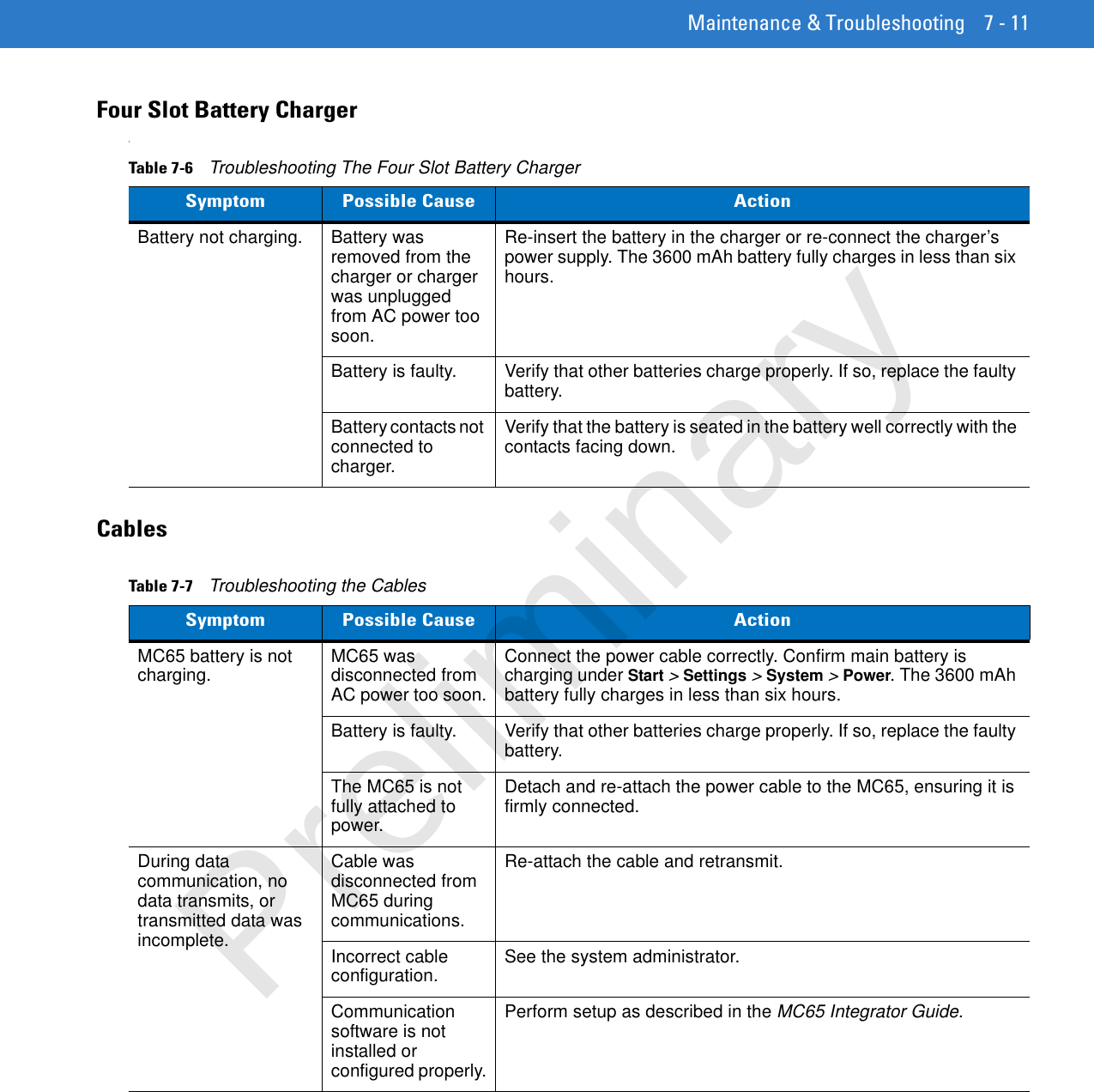
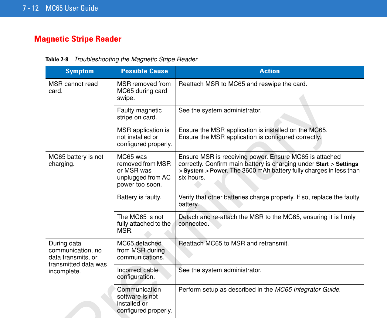
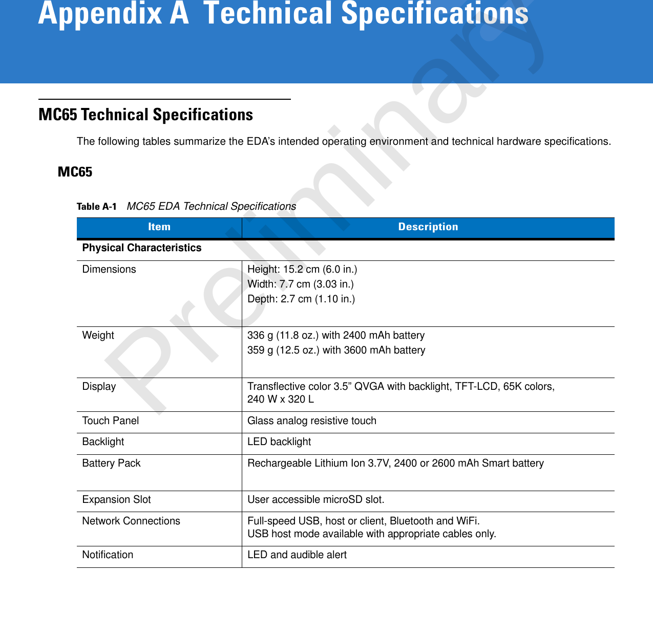
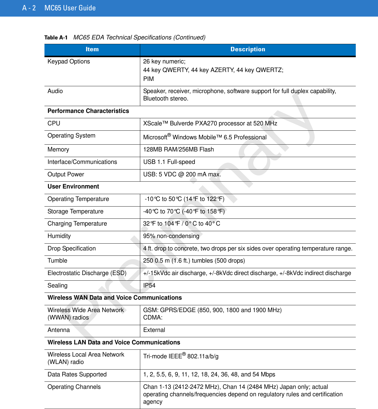
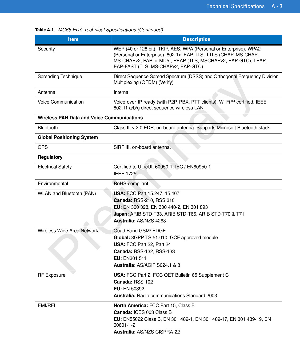
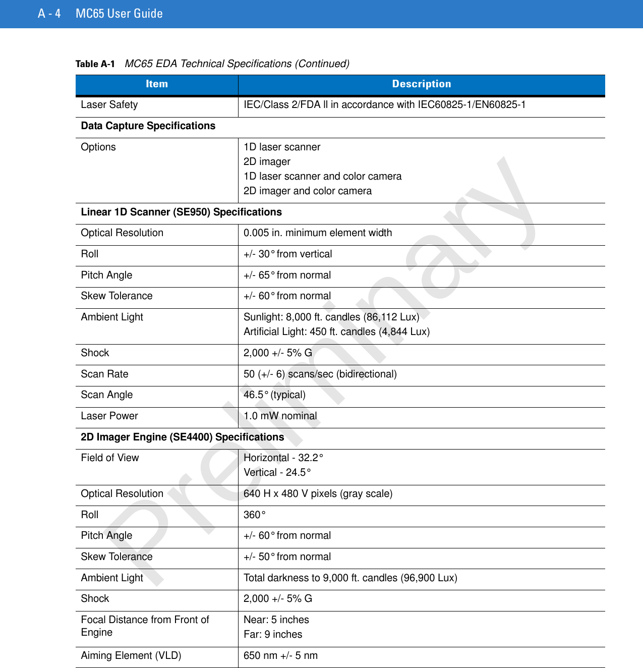
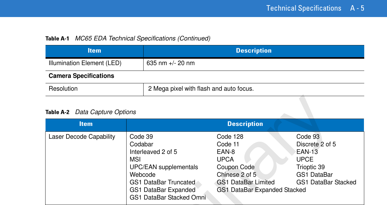
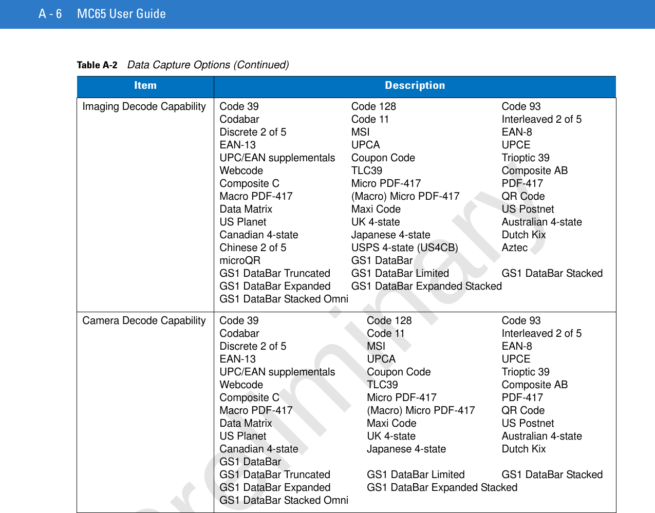
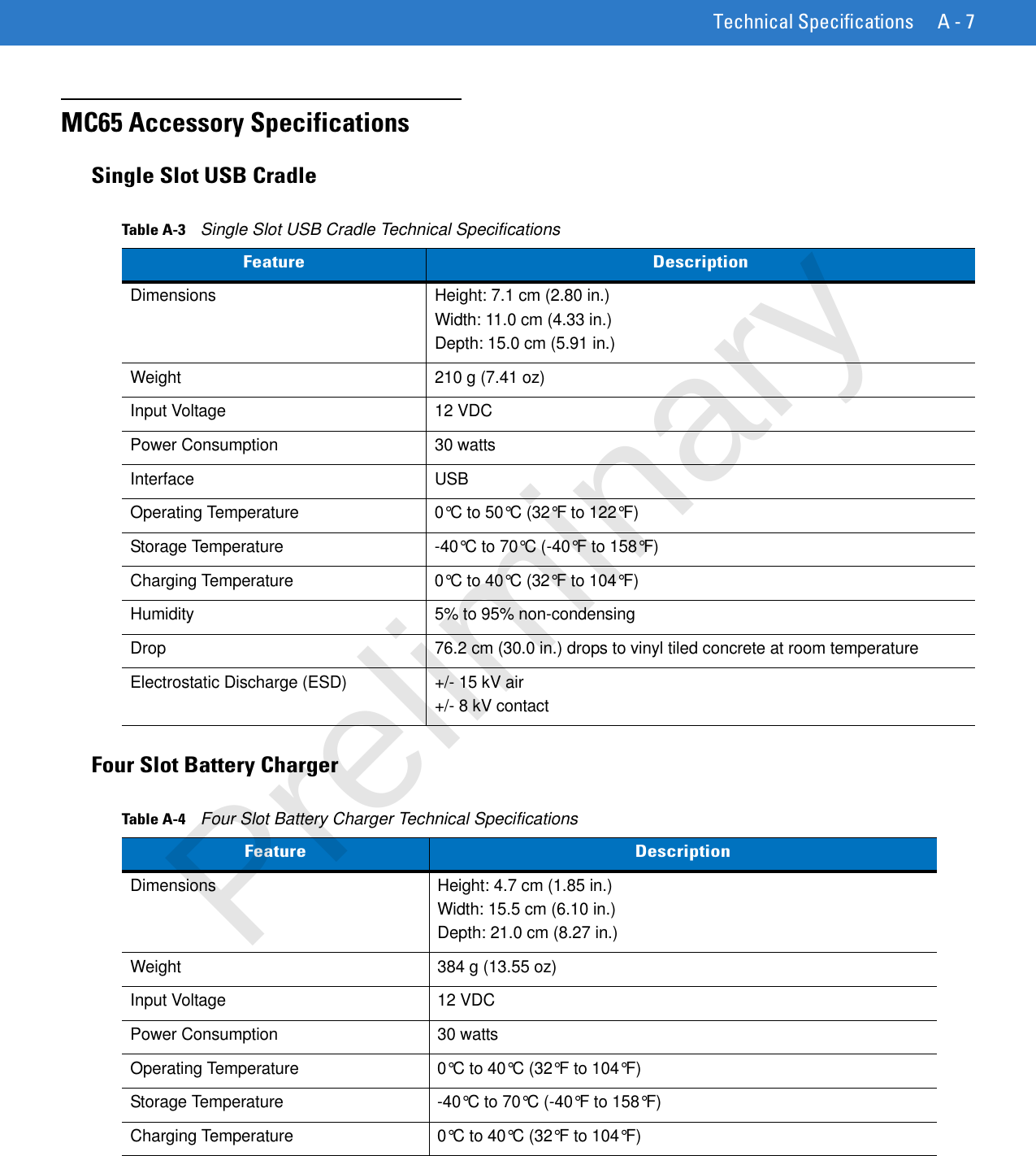
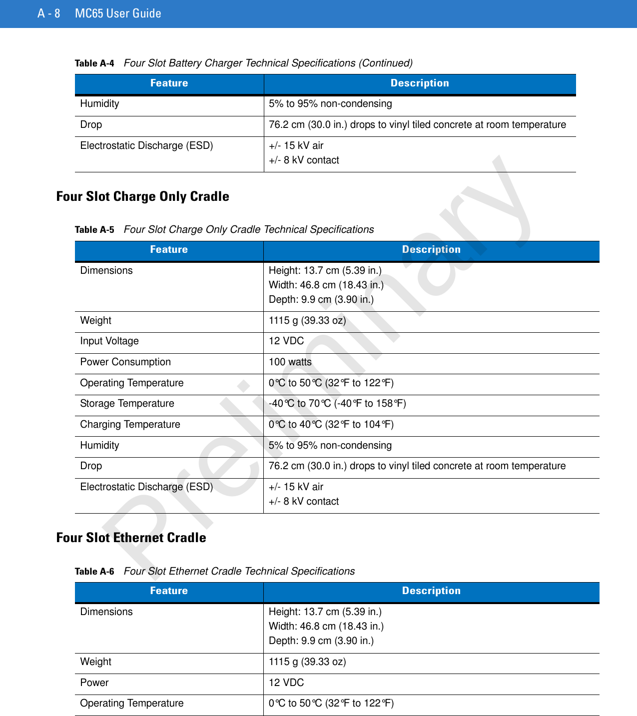
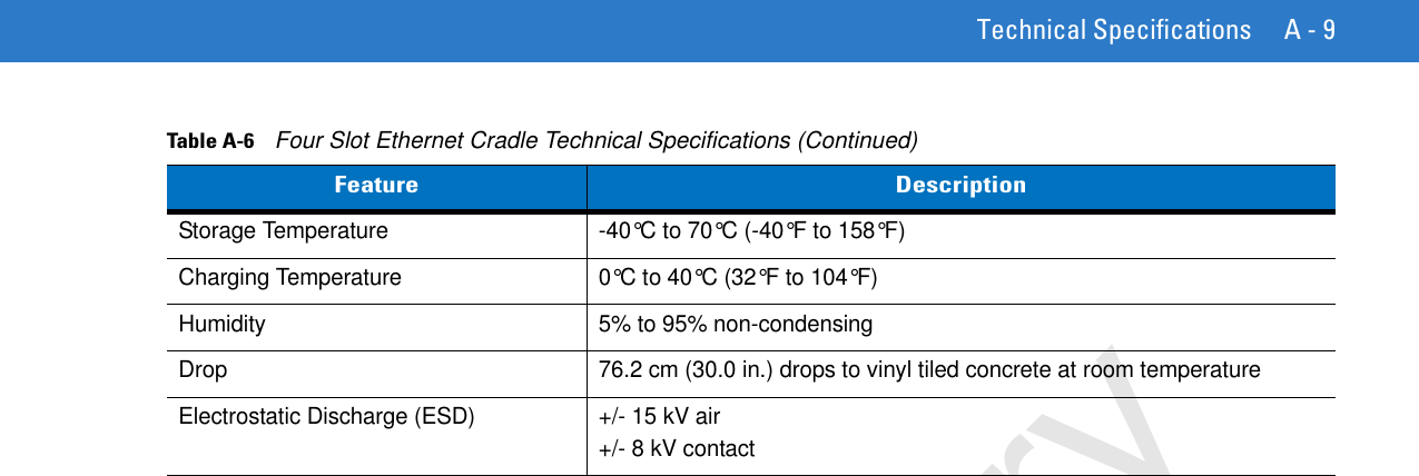
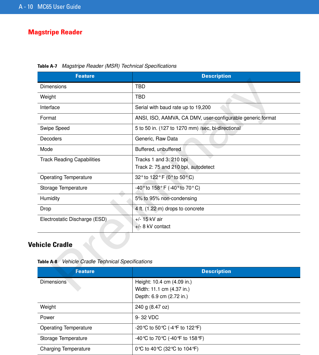
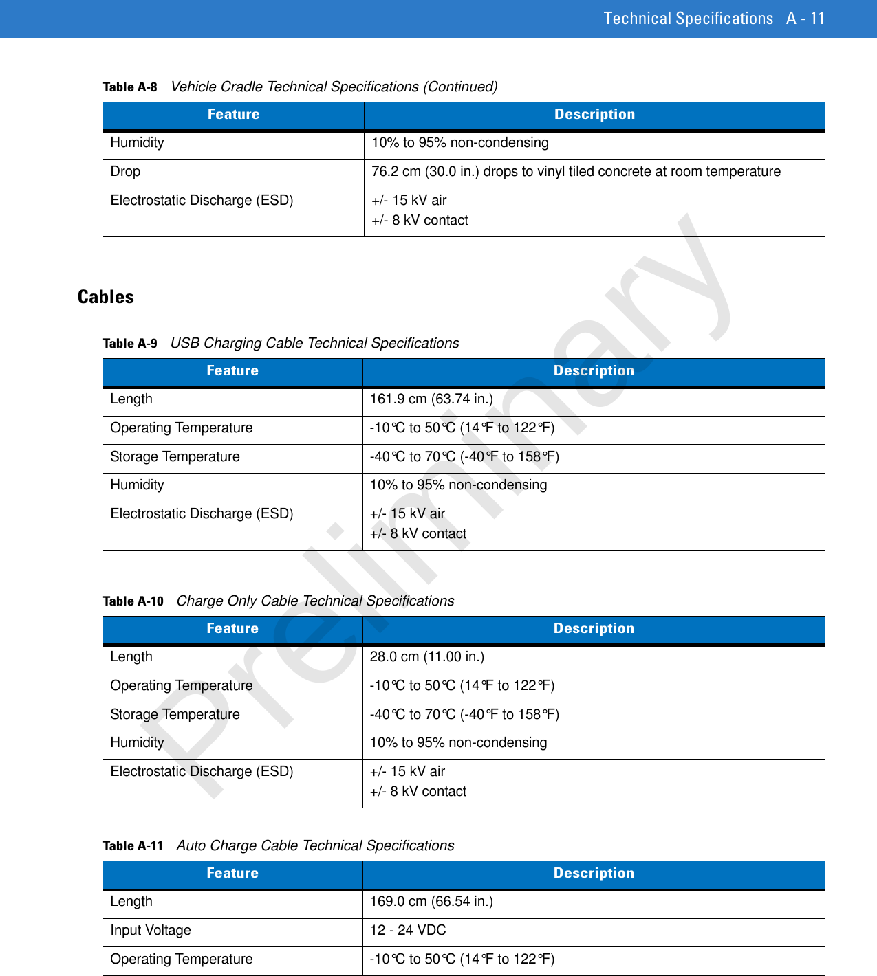
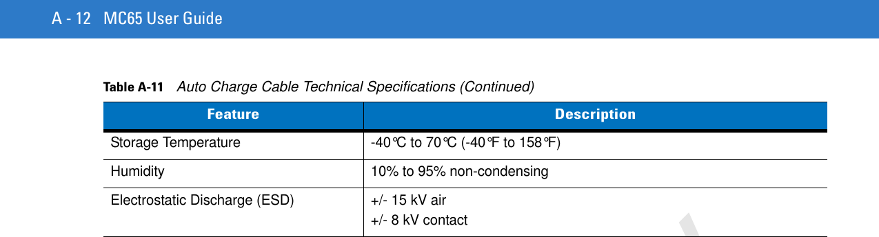
Users Manual 3