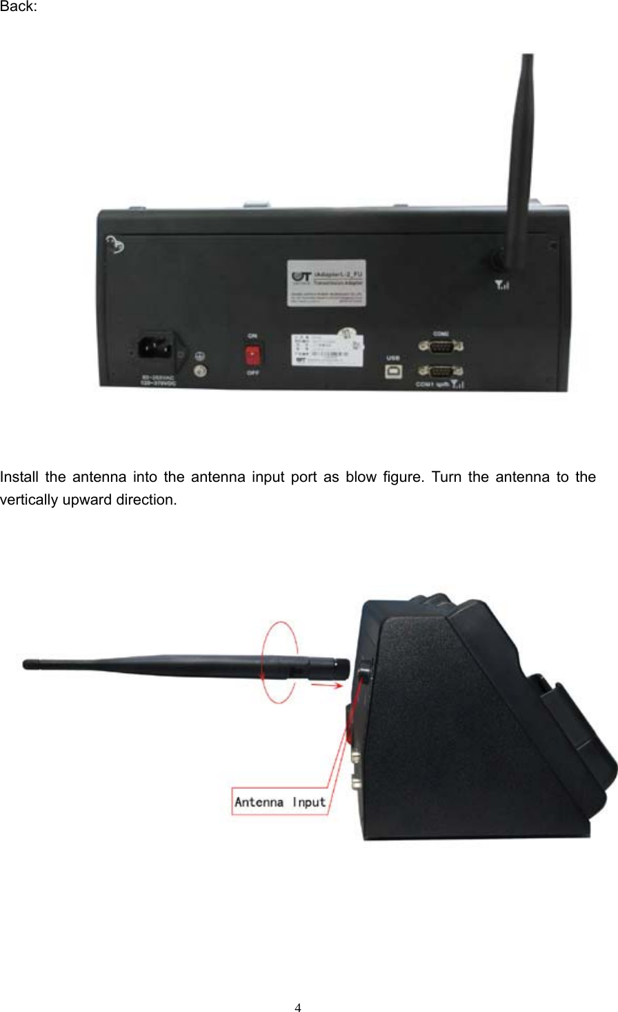
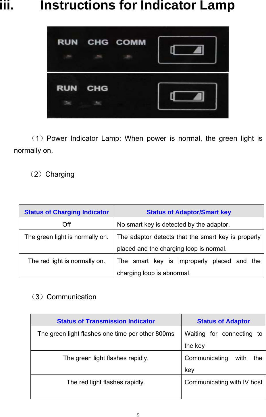
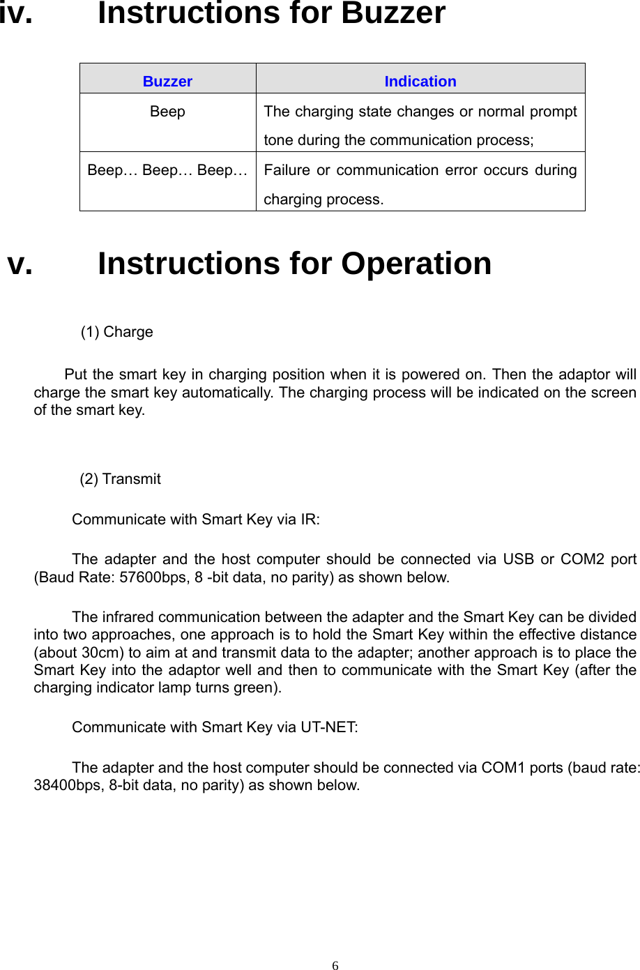
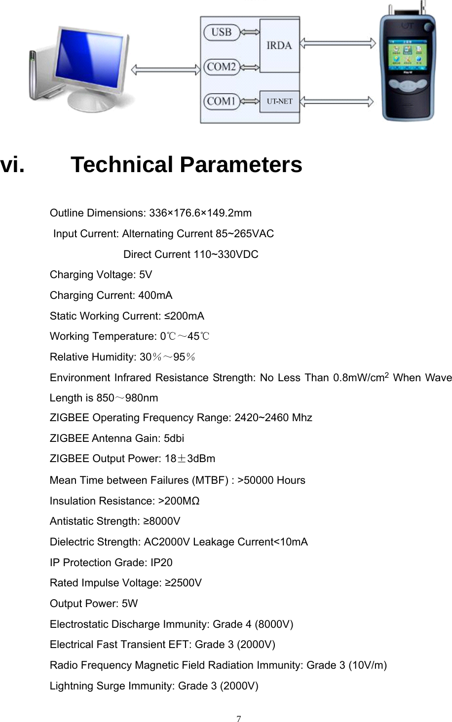
Zhuhai Unitech Power Technology IADAPTERL Transmission Adaptor (Zigbee) User Manual

Zhuhai Unitech Power Technology Co., Ltd. Transmission Adaptor (Zigbee) Users Manual

Users Manual

0                   Document No.: TSS-iAdapterL2_FU-001 Version No.: V1.0   IADAPTERL-2_FU TRANSMISSION ADAPTOR  USER MANUAL    Total 5 Pages         Formulated by: Mo Yiting Audited by: Yang Shaohua Reviewed by: Xu Yinhua     Countersigned by: Ma Jinhui Approved by: Li Baofu  Zhuhai Unitech Power Technology Co., Ltd.   Sept. 7th, 2011
1    Modification Records Date   Version   Modification   Modifier  Approver 2011.9.7 V1.0  Original version Mo Yiting Li Baofu
2   Contents  i. Introduction .............................................................................................................................. 3 ii. Appearance ............................................................................................................................. 3 iii. Instructions for Indicator Lamp ............................................................................................. 5 iv. Instructions for Buzzer ........................................................................................................... 6 v. Instructions for Operation ...................................................................................................... 6 vi. Technical Parameters ............................................................................................................ 7 vii. Warning .................................................................................................................................... 8
3  i. Introduction  The iAdapterL-2_FU adaptor is used in conjunctions with “UT2000IV operation order expert system” or “JOYO-J centralized control system” , which can be communicated with the host computer via USB and serial ports, the iAdapterL-2_FU adaptor doesn’t require any configuration in communication via USB and serial port, but the Zigbee module needs to be configured under the UT-NET communication mode.   The iAdapterL-2_FU adaptor is provided with two sockets for smart key, both sockets can function as a charger, but only the right socket can be used for communication. Note: USB interface will be unavailable about this product. ii. Appearance  Front:
4  Back: Install the antenna into the antenna input port as blow figure. Turn the antenna to the vertically upward direction.
5  iii.  Instructions for Indicator Lamp    (1)Power Indicator Lamp: When power is normal, the green light is normally on.  (2)Charging    (3)Communication  Status of Transmission Indicator  Status of Adaptor The green light flashes one time per other 800ms  Waiting for connecting to the key The green light flashes rapidly.   Communicating with the key The red light flashes rapidly.  Communicating with IV host Status of Charging Indicator  Status of Adaptor/Smart key Off    No smart key is detected by the adaptor. The green light is normally on. The adaptor detects that the smart key is properly placed and the charging loop is normal.   The red light is normally on.  The  smart key is improperly placed and the charging loop is abnormal.
6   iv. Instructions for Buzzer Buzzer   Indication Beep  The charging state changes or normal prompt tone during the communication process; Beep… Beep… Beep…  Failure or communication error occurs during charging process. v. Instructions for Operation  (1) Charge Put the smart key in charging position when it is powered on. Then the adaptor will charge the smart key automatically. The charging process will be indicated on the screen of the smart key.   (2) Transmit Communicate with Smart Key via IR: The adapter and the host computer should be connected via USB or COM2 port (Baud Rate: 57600bps, 8 -bit data, no parity) as shown below. The infrared communication between the adapter and the Smart Key can be divided into two approaches, one approach is to hold the Smart Key within the effective distance (about 30cm) to aim at and transmit data to the adapter; another approach is to place the Smart Key into the adaptor well and then to communicate with the Smart Key (after the charging indicator lamp turns green). Communicate with Smart Key via UT-NET: The adapter and the host computer should be connected via COM1 ports (baud rate: 38400bps, 8-bit data, no parity) as shown below.
7   vi. Technical Parameters Outline Dimensions: 336×176.6×149.2mm Input Current: Alternating Current 85~265VAC              Direct Current 110~330VDC Charging Voltage: 5V Charging Current: 400mA Static Working Current: ≤200mA Working Temperature: 0℃~45℃ Relative Humidity: 30%~95% Environment Infrared Resistance Strength: No Less Than 0.8mW/cm2 When Wave Length is 850~980nm ZIGBEE Operating Frequency Range: 2420~2460 Mhz ZIGBEE Antenna Gain: 5dbi ZIGBEE Output Power: 18±3dBm Mean Time between Failures (MTBF) : >50000 Hours Insulation Resistance: >200MΩ Antistatic Strength: ≥8000V Dielectric Strength: AC2000V Leakage Current<10mA IP Protection Grade: IP20 Rated Impulse Voltage: ≥2500V Output Power: 5W Electrostatic Discharge Immunity: Grade 4 (8000V) Electrical Fast Transient EFT: Grade 3 (2000V) Radio Frequency Magnetic Field Radiation Immunity: Grade 3 (10V/m) Lightning Surge Immunity: Grade 3 (2000V)
8  Radio Frequency Magnetic Field Conduction Immunity: Grade 3 (10V/m) Power Frequency Magnetic Field Immunity: Grade 5 (100A/m) Pulsed Magnetic Field Immunity: Grade 5 (100A/m) vii.  Warning FCC Radiation Exposure Statement:     This equipment complies with FCC radiation exposure limits set forth for an uncontrolled environment .This equipment should be installed and operated with minimum distance 20cm between the radiator& your body.     This transmitter must not be co-located or operating in conjunction with any other antenna or transmitter.     Note: This equipment has been tested and found to comply with the limits for a Class A digital device, pursuant to part 15 of the FCC Rules. These limits are designed to provide reasonable protection against harmful interference when the equipment is operated in a commercial environment. This equipment generates, uses, and can radiate radio frequency energy and, if not installed and used in accordance with the instruction manual, may cause harmful interference to radio communications. Operation of this equipment in a residential area is likely to cause harmful interference in which case the user will be required to correct the interference at his own expense. This device complies with part 15 of the FCC Rules. Operation is subject to the following two conditions: (1) This device may not cause harmful interference, and (2) this device must accept any interference received, including interference that may cause undesired operation.、 changes or modifications not expressly approved by the party responsible for compliance could void the user's authority to operate the equipment. Antenna Installation: WARNING:It is installer’s responsibility to ensure that when using the authorized antennas in the United States(or where FCC rules apply),only those antennas certified with product are used.The use of any antenna other than those certified with the product is expressly forbidden in accordance to FCC rules CFR47 part 15.204.The installer should configure the output power level of antennas,according to country regulations and per antenna type. Professional installation is required of equipment with connectors to ensure compliance with health and safety issues.

Navigation menu