Zoom Telephonics WL1098 Wireless-N Router w 3G+Modem & Voice User Manual
Zoom Telephonics Inc Wireless-N Router w 3G+Modem & Voice
UserManual.wiki
>
Zoom Telephonics
>
WL1098 User Manual
User Manual
Navigation menu
Upload a User Manual
Namespaces
Wiki Guide
HTML
PDF
Info
Views
User Manual
Discussion / Help
Navigation
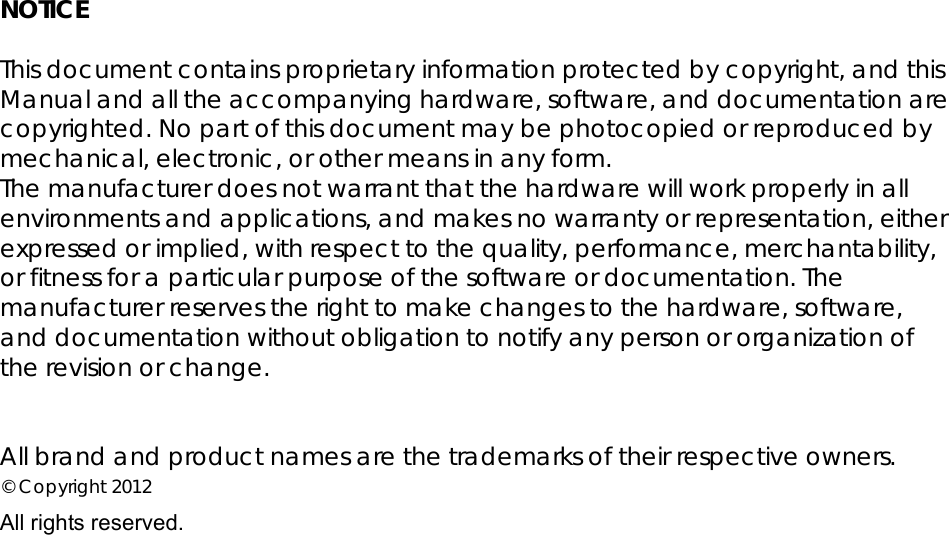
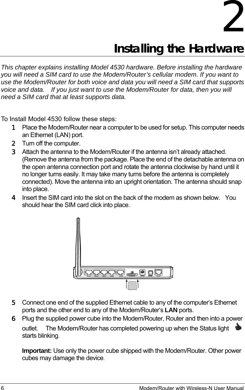
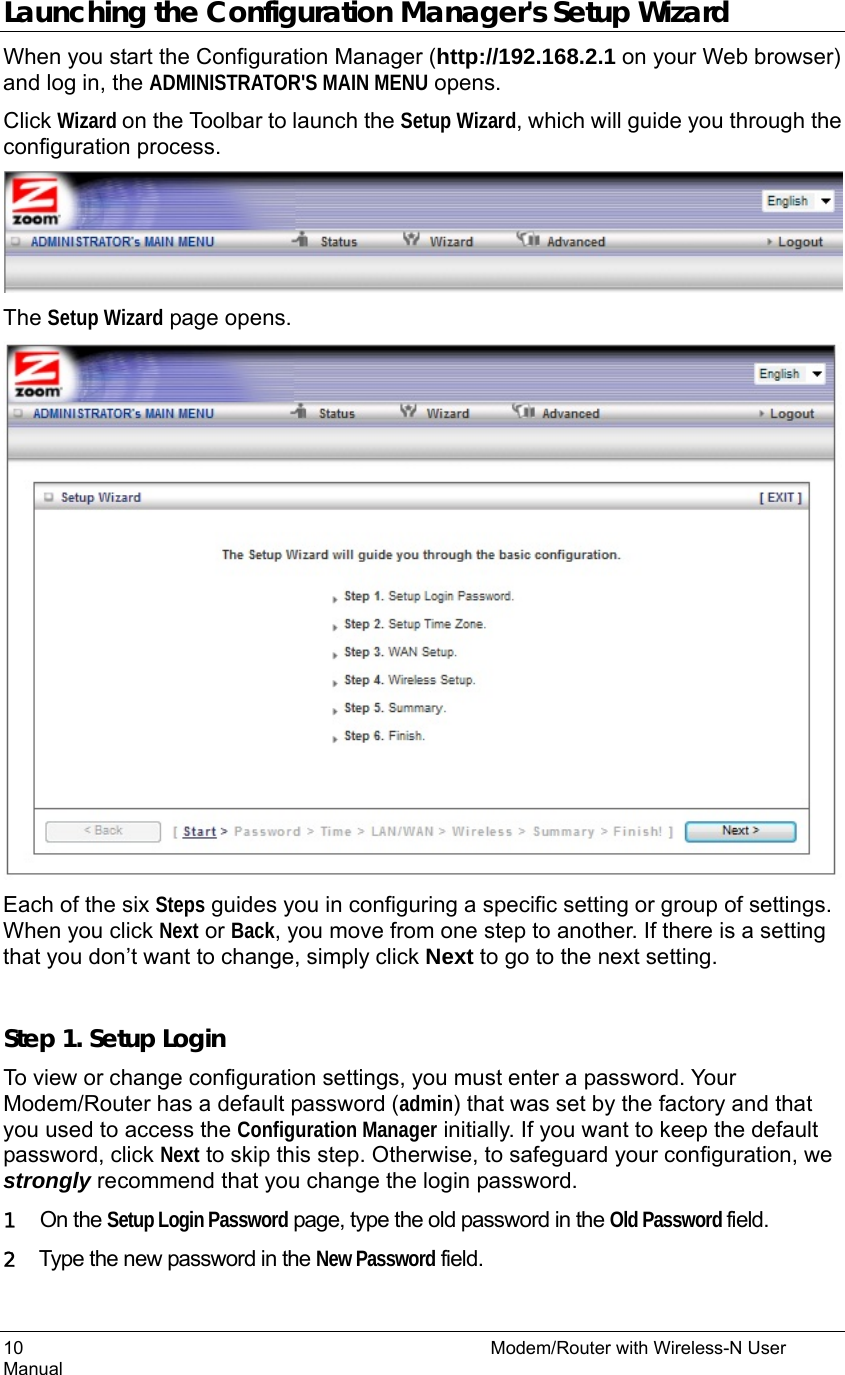
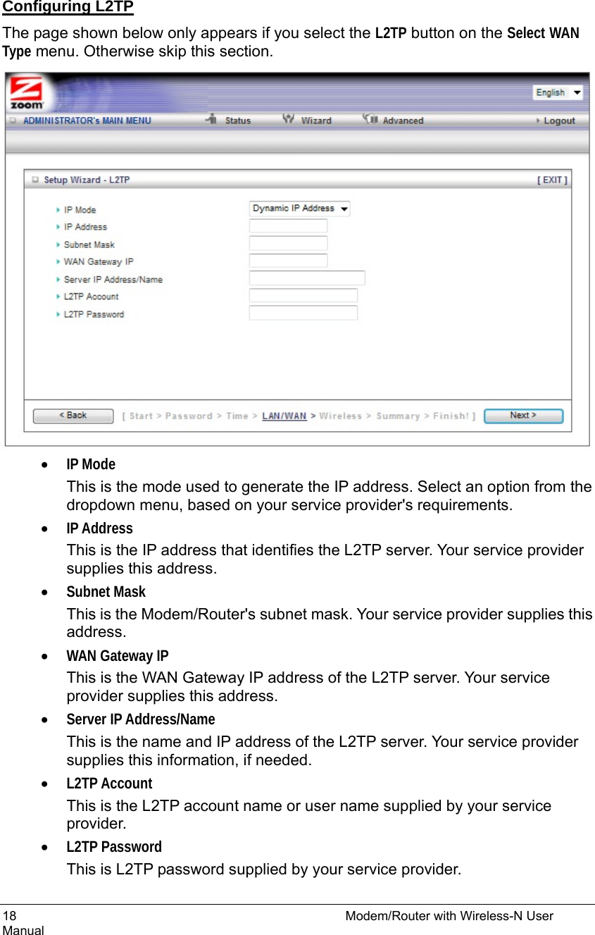
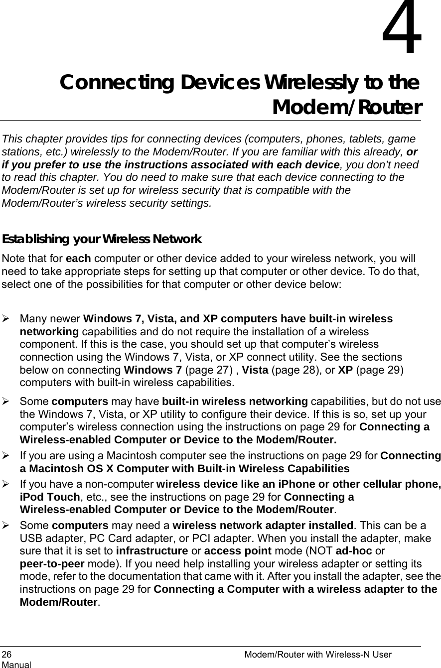
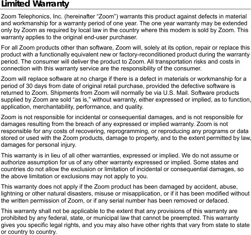
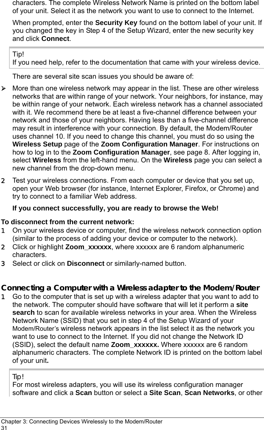
![28 Modem/Router with Wireless-N User Manual 2 Right-click your Wireless Network Name and select Disconnect. Connecting a Windows Vista Computer with Built-in Wireless Capabilities 1 From the Start menu select Connect to. 2 In the wireless network options box, highlight the Wireless Network Name (SSID) you gave your wireless network in Step 4 of the Setup Wizard. If you did not change the Wireless Network Name (SSID), select the default name Zoom_xxxxxx, where xxxxxx are 6 random alphanumeric characters. The complete Wireless Network Name is printed on the bottom label of your unit. If you want to automatically connect to the Modem/Router, click the Connect Automatically box. Then click Connect. • When prompted, enter the Security Key found on the bottom label of your unit. If you changed the key in Step 4 of the Setup Wizard, enter the new security key and click Connect. • If you disabled wireless security in Step 4 of the Setup Wizard select Connect Anyway when warned that your network is unsecure. ¾ When you click on the wireless network option box, Windows will scan for available networks. More than one wireless network may appear in the list. These are other wireless networks that are within range of your network. Your neighbors, for instance, may be within range of your network. Each wireless network has a channel associated with it. We recommend there be at least a five-channel difference between your network and those of your neighbors. Having less than a five-channel difference may result in interference with your connection. By default, the Modem/Router uses channel 10. If you need to change this channel, you must do so using the Wireless Setup page of the Zoom Configuration Manager. For instructions on how to log in to the Zoom Configuration Manager, see page 8. After logging in, select Wireless from the left-hand menu. On the Wireless page you can select a new channel from the drop-down menu. 3 In the Successfully connected to [desired network] dialog box, you have three options. You can: • Select Save the network and Start this connection automatically if you always want to connect to the same network. Then click Close. The next time you start your computer you will automatically connect to the selected network. • Select Save the network and clear the Start this connection automatically check box if you don't want to automatically connect to this network every time you start your computer but you will want to connect in the future. Click Close to display the Select a location . . . dialog box where you choose a location. Windows Vista automatically applies the correct network security settings. If the User Account Control dialog box appears, click Continue. • Click Close to complete the connection procedure. Select this option if you are connecting to this network only one time.](https://usermanual.wiki/Zoom-Telephonics/WL1098/User-Guide-1766429-Page-28.png)
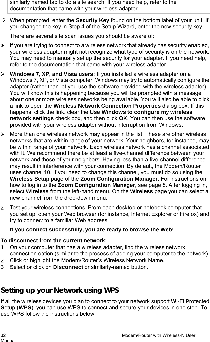

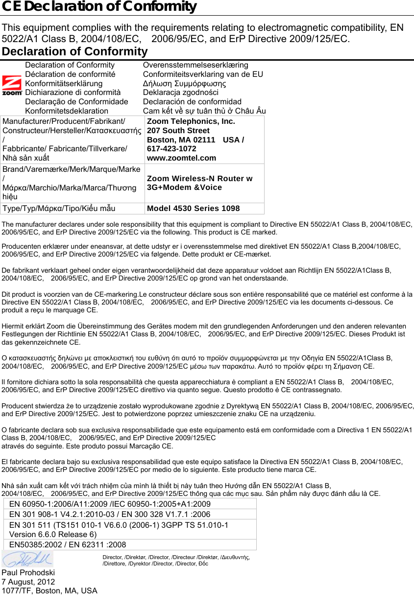
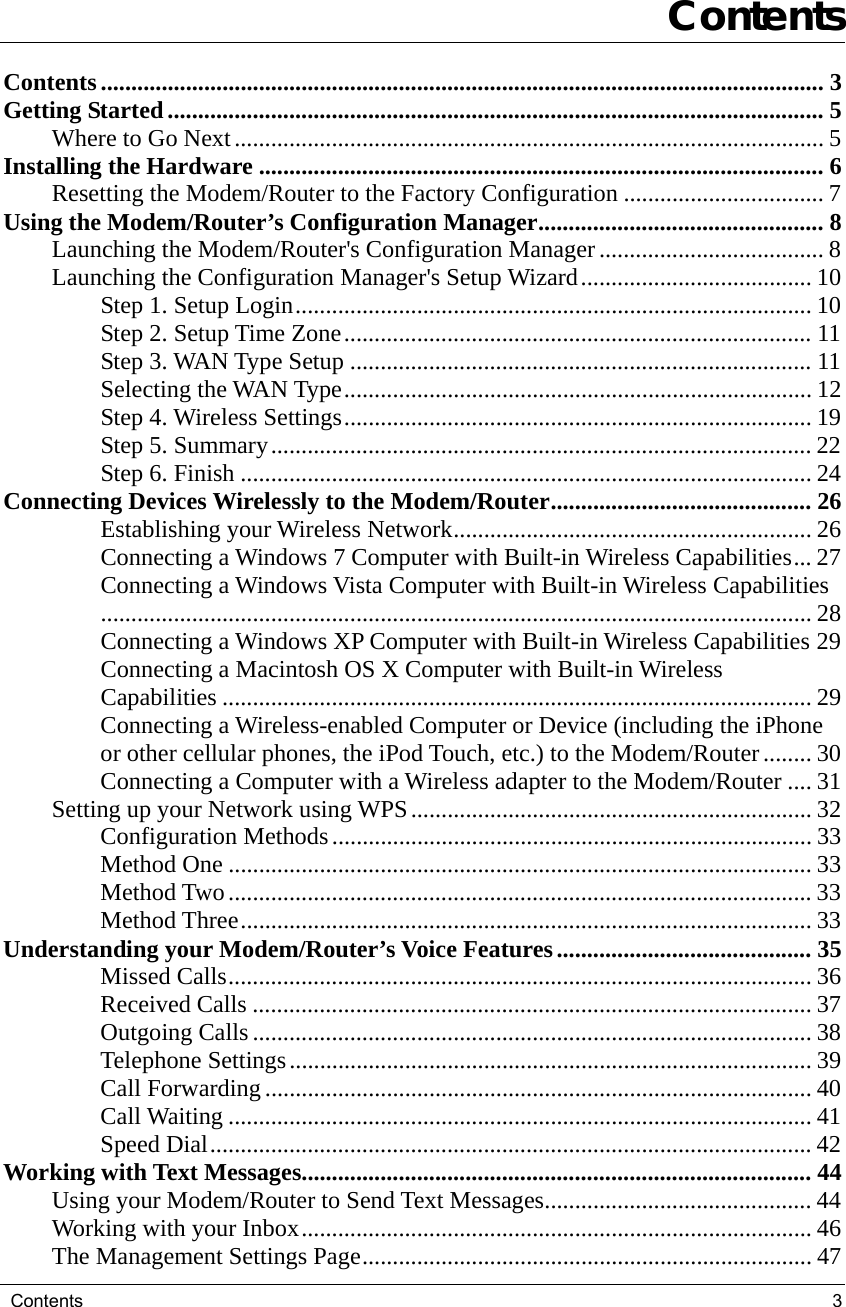
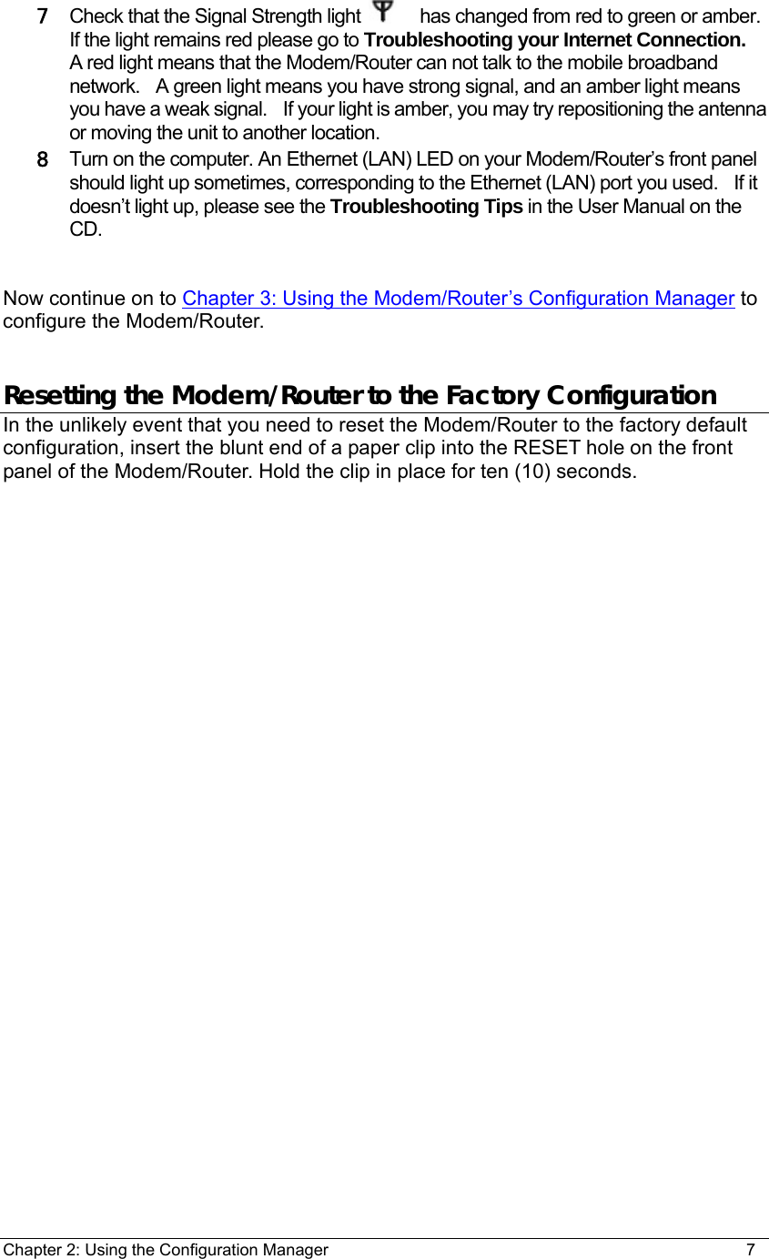
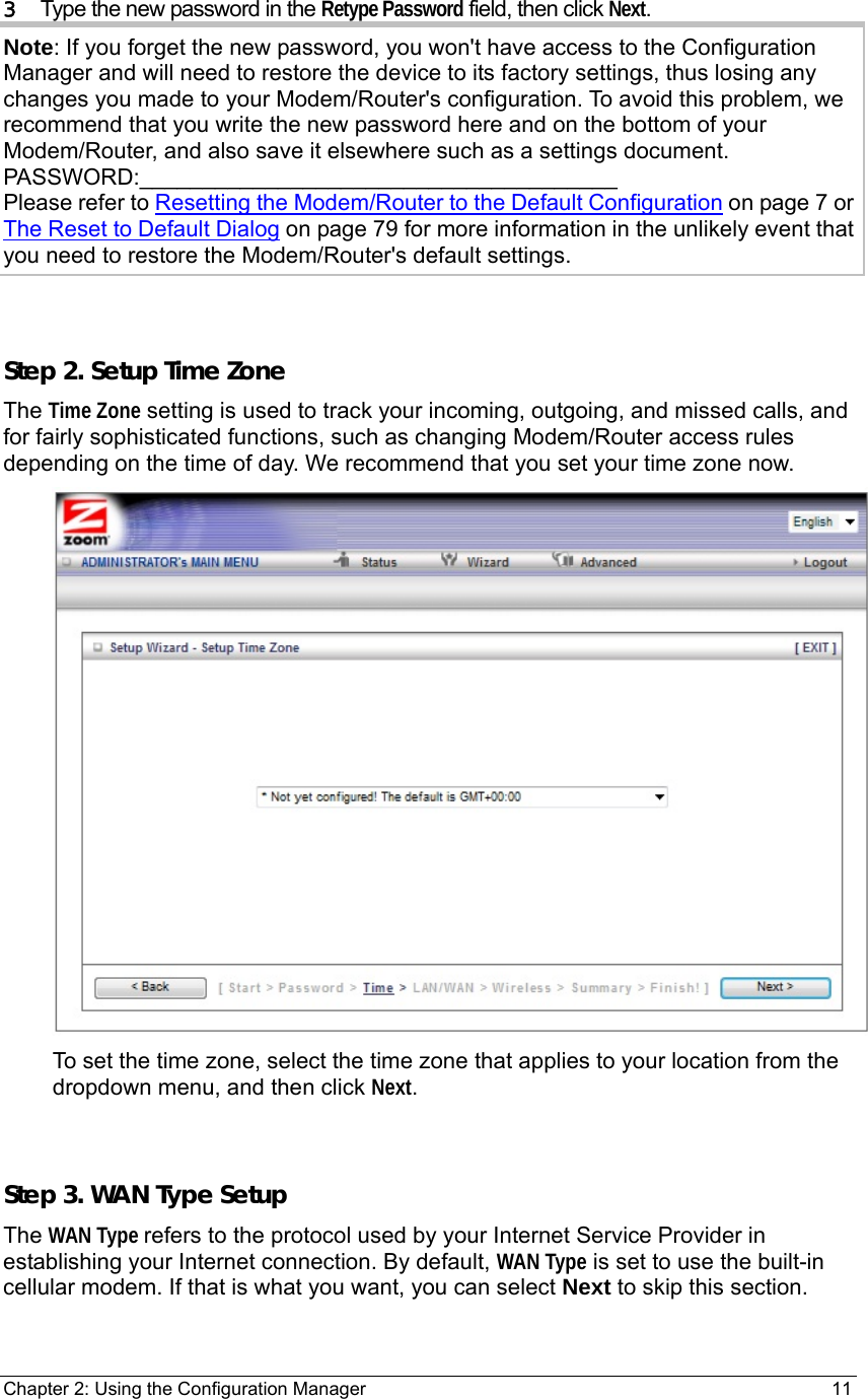
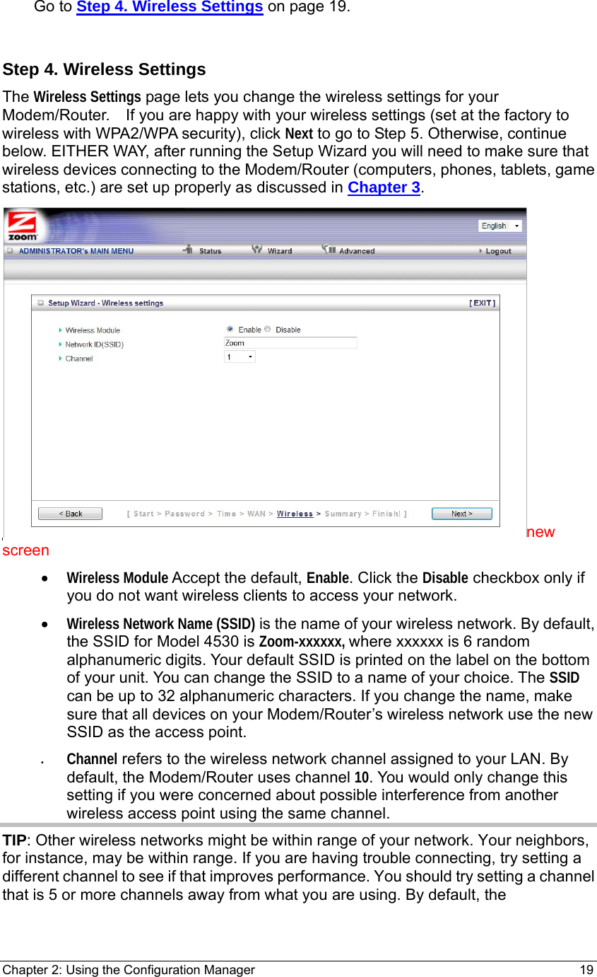
![¾ You want to connect the Modem/Router to your ADSL or cable modem, using the built-in 3G+ modem as a backup Internet connection. See The Basic Setup Page on page 51 for details. ¾ You want to change the default wireless security on your Modem/Router. See Wireless Security on page xx for details. ¾ You want to enable security on the built-in 3G+ modem. See Pin Codes on page xx ¾ You want to back up Modem/Router settings that you made using the Configuration Manager. See The Backup Setting Dialog on page 79 for details. Online Help The Advanced program provides both online and context-sensitive help that guides you in changing the settings on each menu. Need to check ¾ To access online help, click [HELP] on the menu's Toolbar. Each [HELP] page describes the fields on the active page and, when applicable, the required or recommended entries. ¾ The context-sensitive help automatically displays a question mark to the right of the cursor, then opens a message box in the left pane of the page. The message box contains text that describes the active field and its required or recommended entry. Launching the Configuration Manager's Advanced Program If you are connected to the Modem/Router through your computer’s Ethernet port, you can go right ahead and log into the configuration manager. If you are using a wireless connection to access the Modem/Router, you must first set up the wireless connection. If you are unsure how to set up a wireless connection see Establishing your Wireless Network on page 26. Turn on your computer and Modem/Router, then launch your Web browser. 9 In the Web browser address bar, type the Modem/Router's default IP address, http://192.168.2.1 and then click Enter to launch the Configuration Manager. When the Configuration Manager's MAIN MENU opens, it displays a Status page that summarizes the basic settings and current values for your setup. 10 On the Toolbar, type the login password -- admin is the default password -- in the System Password field, and then click Login. 11 Click Advanced on the Toolbar to launch the Advanced program.](https://usermanual.wiki/Zoom-Telephonics/WL1098/User-Guide-1766429-Page-50.png)
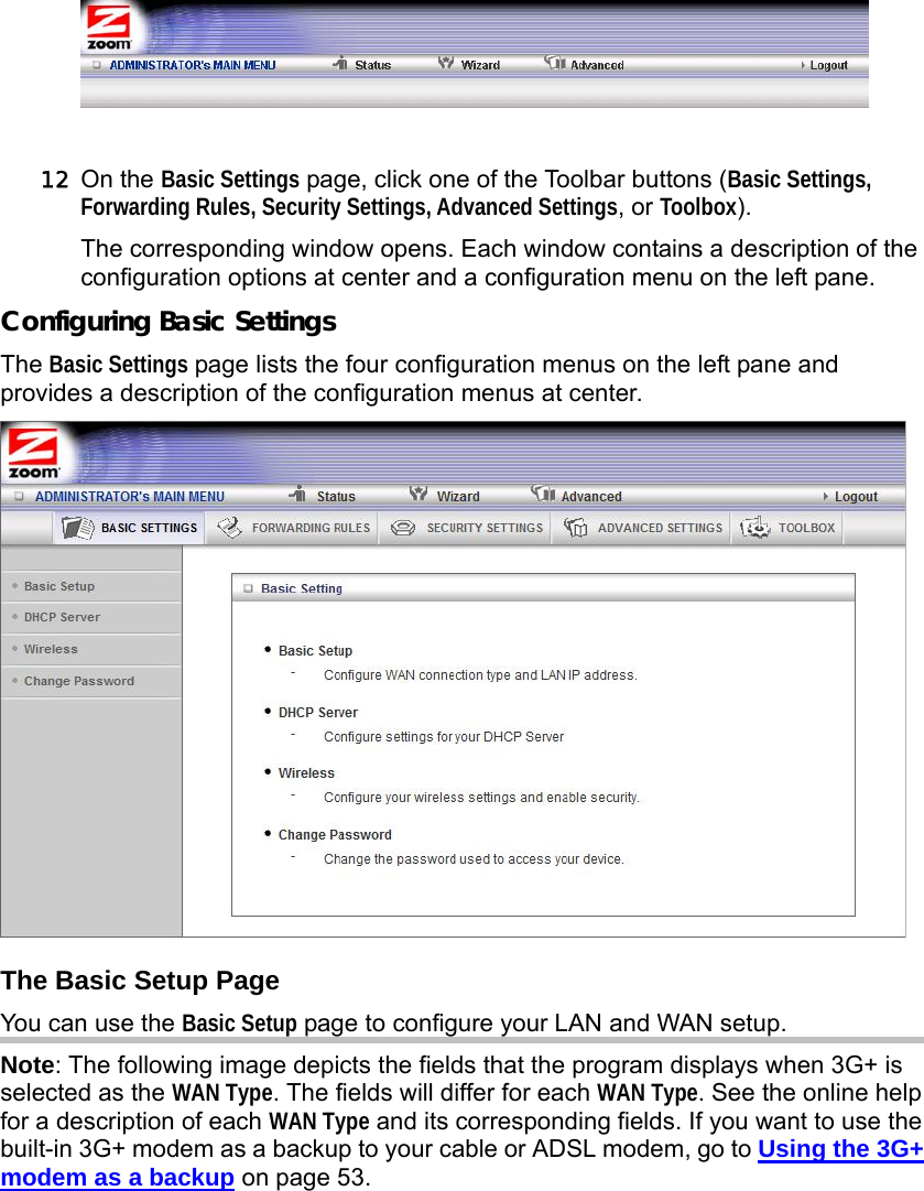
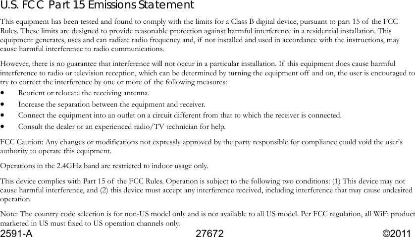
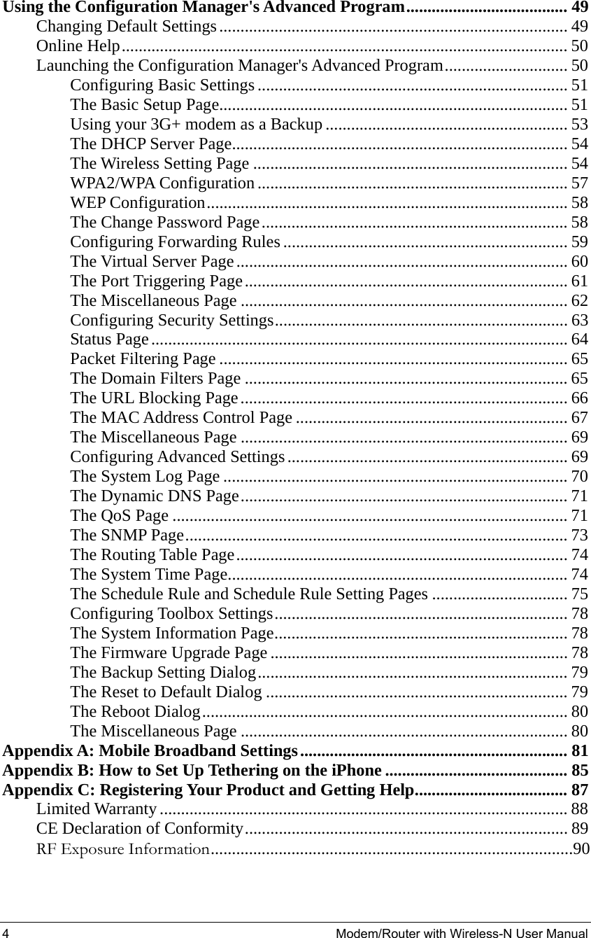
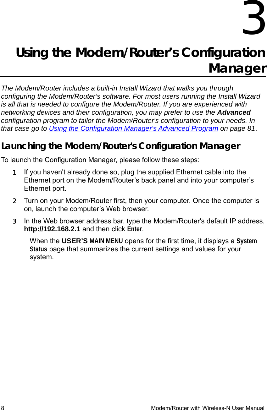
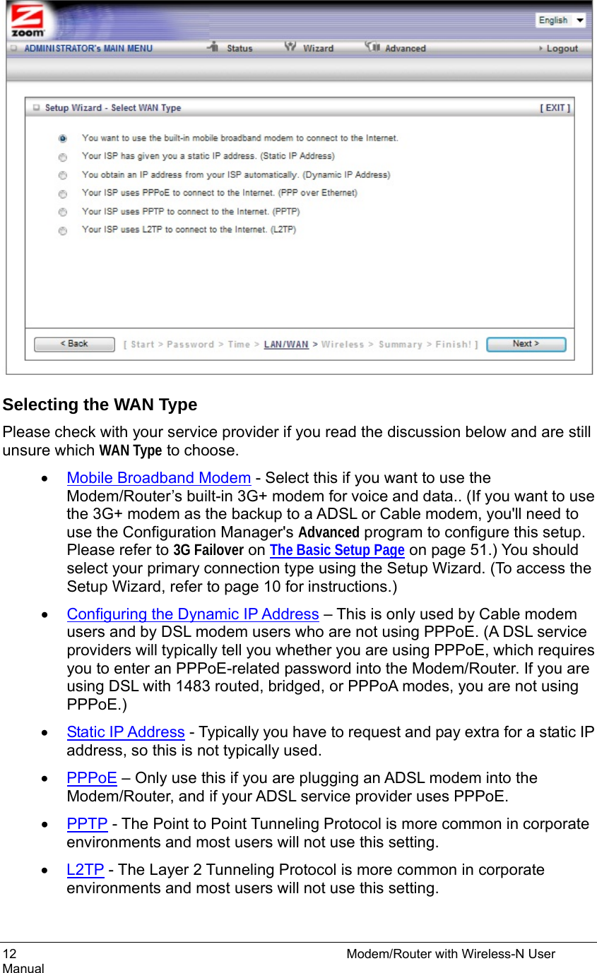
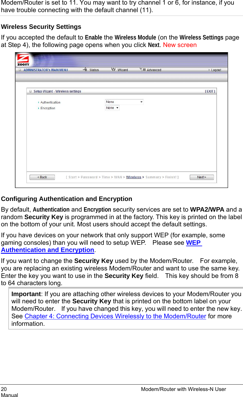
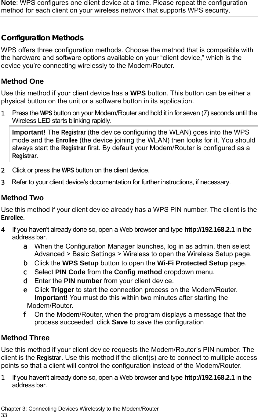
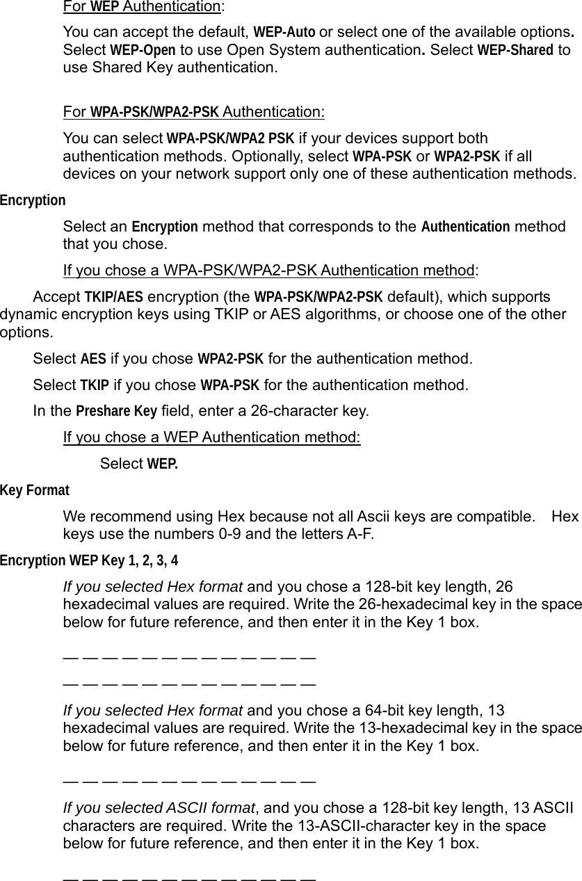
![The DHCP Server Page You can use the DHCP Server page to configure your DHCP server. If you want to change the default values, please click [HELP], which opens a page that describes each item and the recommended values. The Wireless Setting Page You can use the Wireless Setting page to configure your wireless LAN setup. If you want to change the default values, please click [HELP], which opens a page that describes each item and the recommended values. Wireless Module Accept the default, Enable. Click the Disable checkbox only if you do not want wireless clients to access your network.](https://usermanual.wiki/Zoom-Telephonics/WL1098/User-Guide-1766429-Page-54.png)

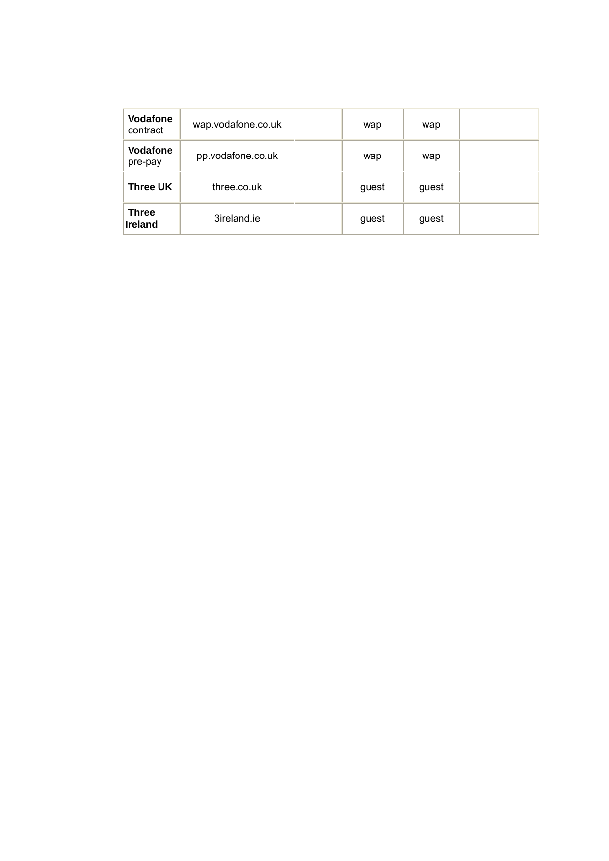
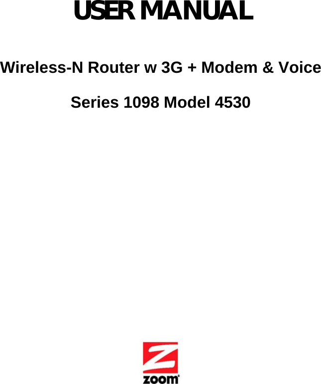
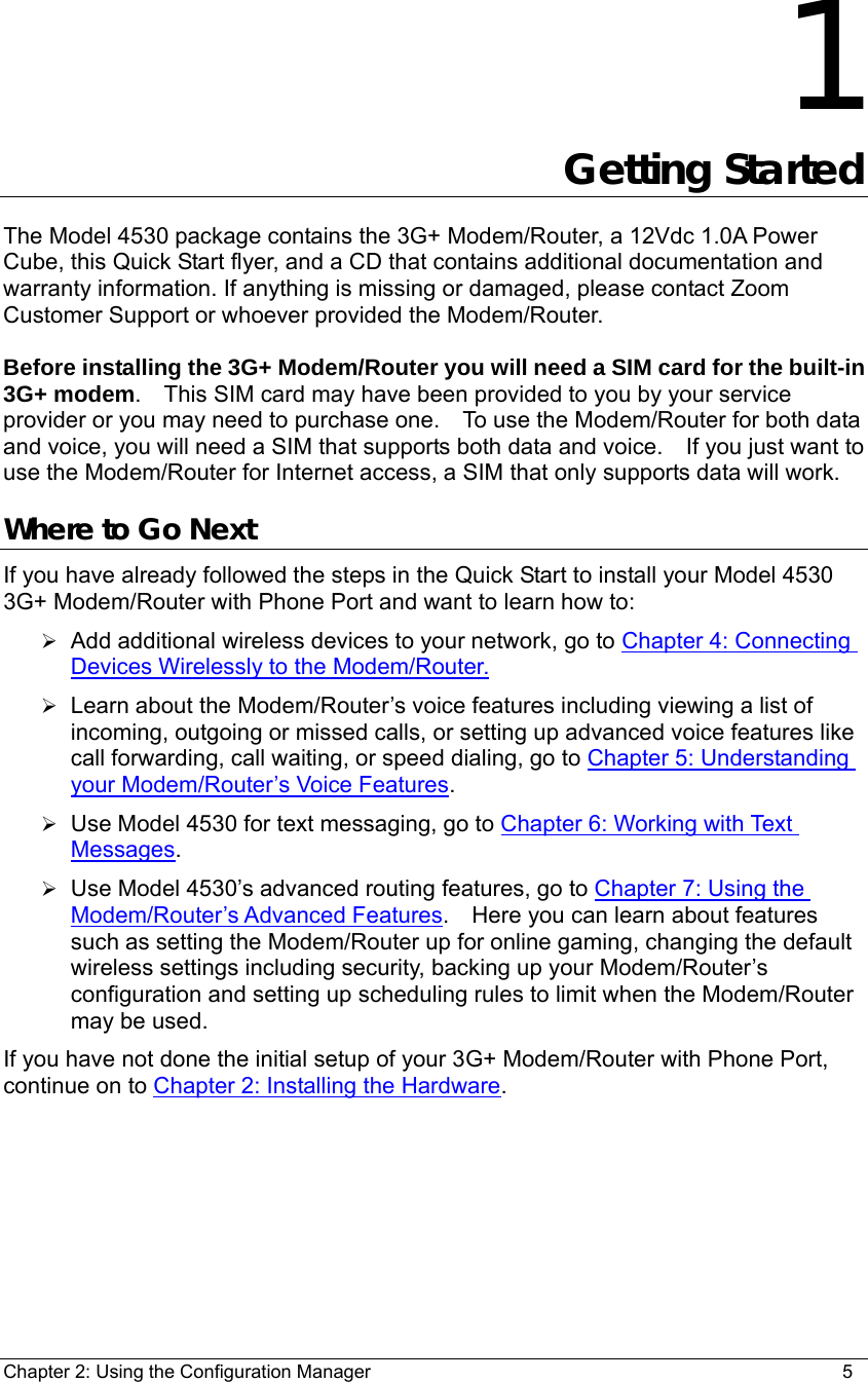
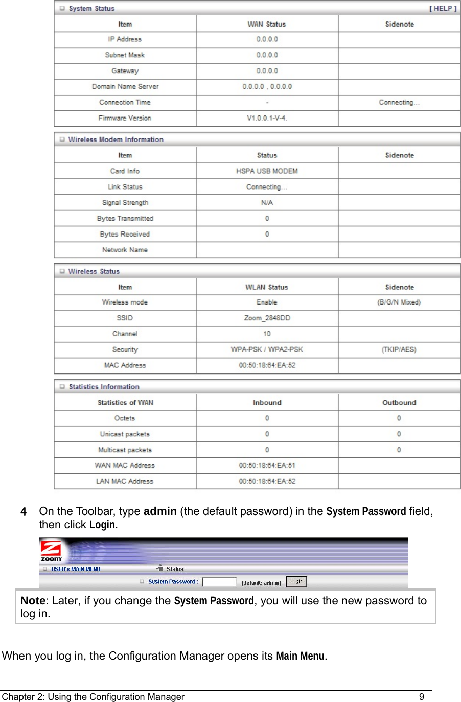
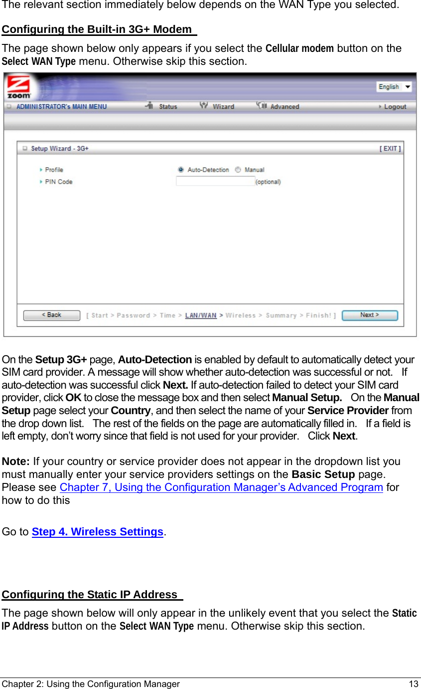
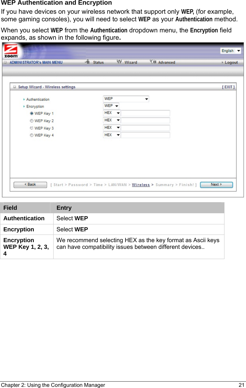
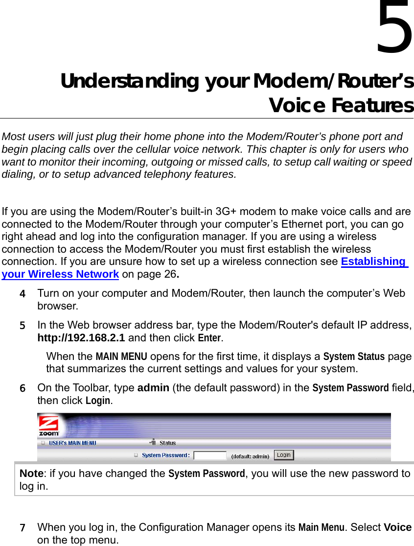
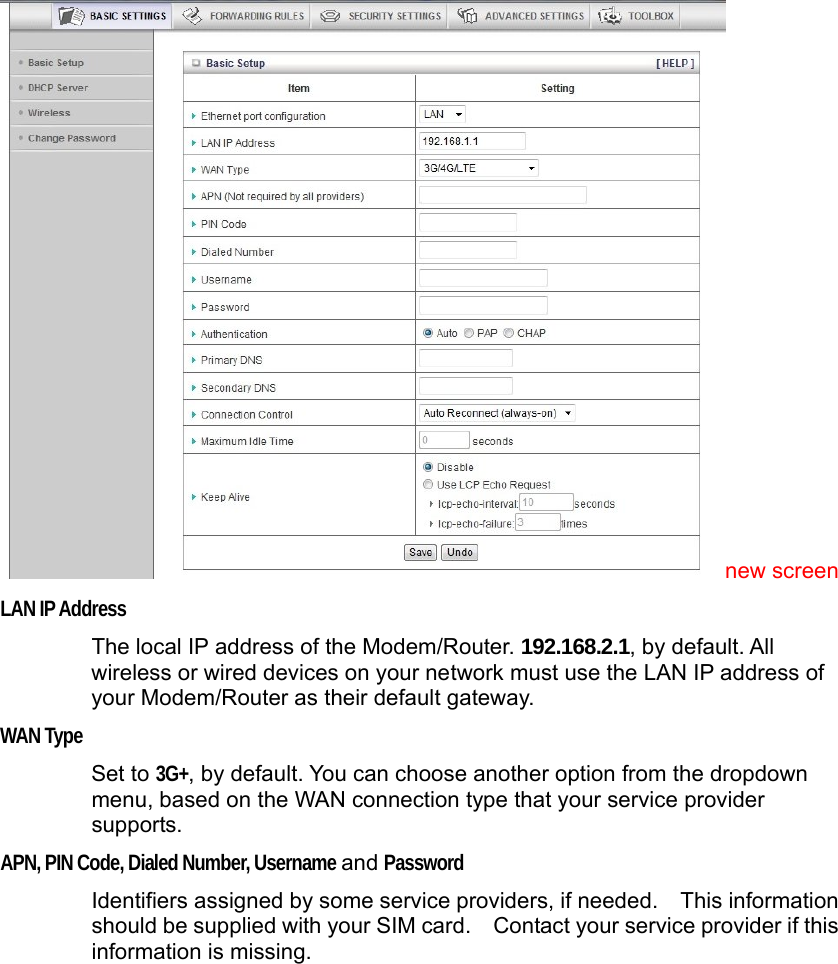
![BT Mobile Customer Value btmobile2.bt.com *99***1# bt bt Jersey Telecom pepper abc abc Jersey Telecom pepper *99# Manx Telecom internet Meteor isp.mymeteor.ie my meteor O2 (1) with contract mobile.o2.co.uk web password O2 (2) with contract mobile.o2.co.uk *99# OR *99***1# o2web OR faster password DNS Address (if needed): 193.113.200.201 O2 (1) faster, with contract mobile.o2.co.uk faster password O2 (2) faster, with contract mobile.o2.co.uk *99# OR *99***1# faster OR o2web password DNS Address (if needed): 193.113.200.201 O2 pre-pay payandgo.o2.co.uk payandgo payandgo Orange Pay Monthly orangeinternet user pass Orange Pay and Go orangewap Multimedia Orange T-Mobile general.t-mobile.co.uk user pass Tesco Mobile prepay.tesco-mobile.com tescowap password Virgin Mobile (1) goto.virginmobile.com user [space] Virgin Mobile (2) goto.virginmobile.com *99# Leave blank Leave blank Authentication:PAP Vodafone ppbundle.internet web web Vodafone contract internet web webs](https://usermanual.wiki/Zoom-Telephonics/WL1098/User-Guide-1766429-Page-83.png)