id Systems MVAC30 OBDII tracking Device User Manual 055 00000889 RevB UTP1 0 installation
I.D. Systems Inc. OBDII tracking Device 055 00000889 RevB UTP1 0 installation
UserManual.wiki
>
id Systems
>
MVAC30 User Manual
User Manual
Navigation menu
Upload a User Manual
Namespaces
Wiki Guide
HTML
PDF
Info
Views
User Manual
Discussion / Help
Navigation
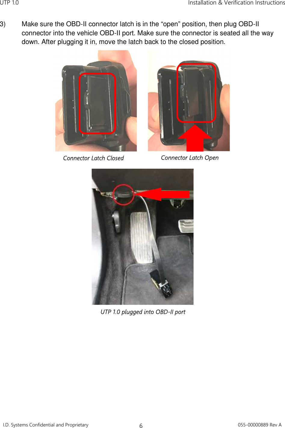
![UTP 1.0 Installation & Verification Instructions I.D. Systems Confidential and Proprietary 1 055-00000889 Rev A Copyright © 2017 I.D. Systems, Incorporated. All Rights Reserved. The material contained in this document is protected by the copyright and trade secret laws of the United States and other countries. It may not be reproduced, distributed, or altered in any fashion by any entity (either internal or external to I.D. Systems, except in accordance with applicable agreements, contracts, or licensing, without the express written consent of the Brand or Marketing Communications Director or the business management owner of the material. Disclaimer and Limitations of Liability The information contained in this Guide is subject to change without notice and should not be construed as a specification. NOTICE: This device complies with Part 15 of the FCC Rules and with Industry Canada license-exempt RSS standard(s)]. Operation is subject to the following two conditions: (1) this device may not cause harmful interference, and (2) this device must accept any interference received, including interference that may cause undesired operation. Le présent appareil est conforme aux CNR d'Industrie Canada applicables aux appareils radio exempts de licence. L'exploitation est autorisée aux deux conditions suivantes: (1) l'appareil ne doit pas produire de brouillage, et (2) l'appareil doit accepter tout brouillage radioélectrique subi, même si le brouillage est susceptible d'en compromettre le fonctionnement. NOTICE: Changes or modifications made to this equipment not expressly approved by I.D. Systems may void the FCC authorization to operate this equipment. To comply with FCC/IC RF exposure limits for general population / uncontrolled exposure, the antenna(s) used for this transmitter must be installed to provide a separation distance of at least 20 cm from all persons and must not be co-located or operating in conjunction with any other antenna or transmitter.](https://usermanual.wiki/id-Systems/MVAC30/User-Guide-3671912-Page-2.png)