ip access KU02ZZS GSM/GPRS/EDGE/AMR picocellular base station operating at 1900MHz. User Manual NGSM GST 300 nanoBTS Prod Desc v1 0m0 1 CP
ip.access ltd GSM/GPRS/EDGE/AMR picocellular base station operating at 1900MHz. NGSM GST 300 nanoBTS Prod Desc v1 0m0 1 CP
Contents
- 1. Installation Manual
- 2. Product Description
Product Description
![nanoBTS Product Description Introduction © ip.access Ltd Page 1 1 INTRODUCTION 1.1 Overview This product description gives the technical specification of the 165 and 139/140 series nanoBTSs from ip.access. It describes the basic properties and functionality of the hardware and software. It includes information on the management model supported by the BTS. It does not go into detail on GSM service support beyond the most basic. This is described in the range of Feature Description documents also available from ip.access. 1.2 Related Information [GSM05.05] 3GPP TS05.05; Technical Specification Group GSM/EDGE; Radio Access Network; Radio transmission and reception (Release 1999) [GSM05.08] 3GPP TS05.08; Technical Specification Group GSM/EDGE; Radio Access Network; Radio Subsystem Link Control (Release 1999) [REF_110] nanoGSM BSS MIB Definition (NGSM_REF_110) [INST_300] nanoBTS Installation Manual (NGSM_INST_300) [NGSM_SOC] nanoGSM Statements of Compliance, ip.access [NGSM_APR] nanoGSM Approvals, ip.access 1.3 Terminology AMR Adaptive Multi-Rate ARFCN Absolute Radio Frequency Channel Number AWG American Wire Gauge BA list Basestation Allocation Backhaul processor Synonym for PPC in this document BHCA Busy-Hour Call Attempts BSC Basestation Controller BSIC Basestation Identity Code BTS Base Transceiver Station CA List Channel Allocation CBCH Cell Broadcast Channel CCCH Common Control Channel CEM Contract Electronics Manufacturer CGI Cell Global Identity Codec Coder-Decoder](https://usermanual.wiki/ip-access/KU02ZZS.Product-Description/User-Guide-1105686-Page-6.png)
![nanoBTS Product Description Series Members © ip.access Ltd Page 4 2 SERIES MEMBERS The 165 series consists of the following products for the GSM bands shown in brackets: • 165A (DCS 1800) • 165B (PCS 1900) • 165C (EGSM 900) • 165D (GSM 850) • 165E (DCS 1800) • 165F (PCS 1900) • 165G (DCS 1800) • 165H (PCS 1900) The 139/40 series consists of the following products for the GSM bands shown in brackets: • 139_ (DCS 1800) • 140_ (PCS 1900) • 177_ (GSM 850) • 178_ (EGSM 900) The band designator is as used in [GSM05.05].](https://usermanual.wiki/ip-access/KU02ZZS.Product-Description/User-Guide-1105686-Page-9.png)
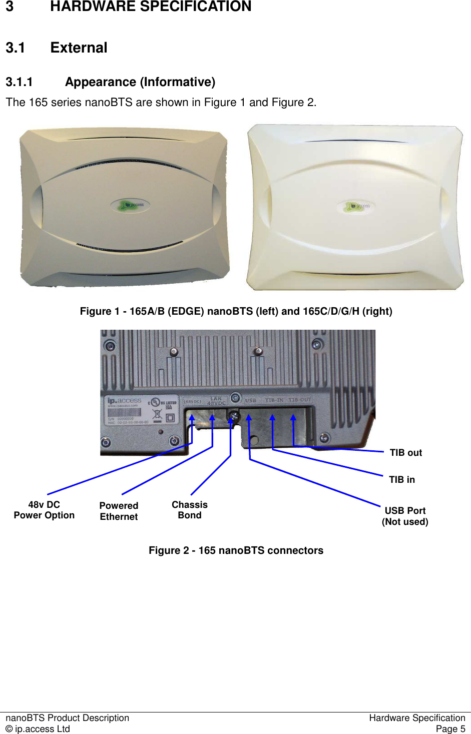
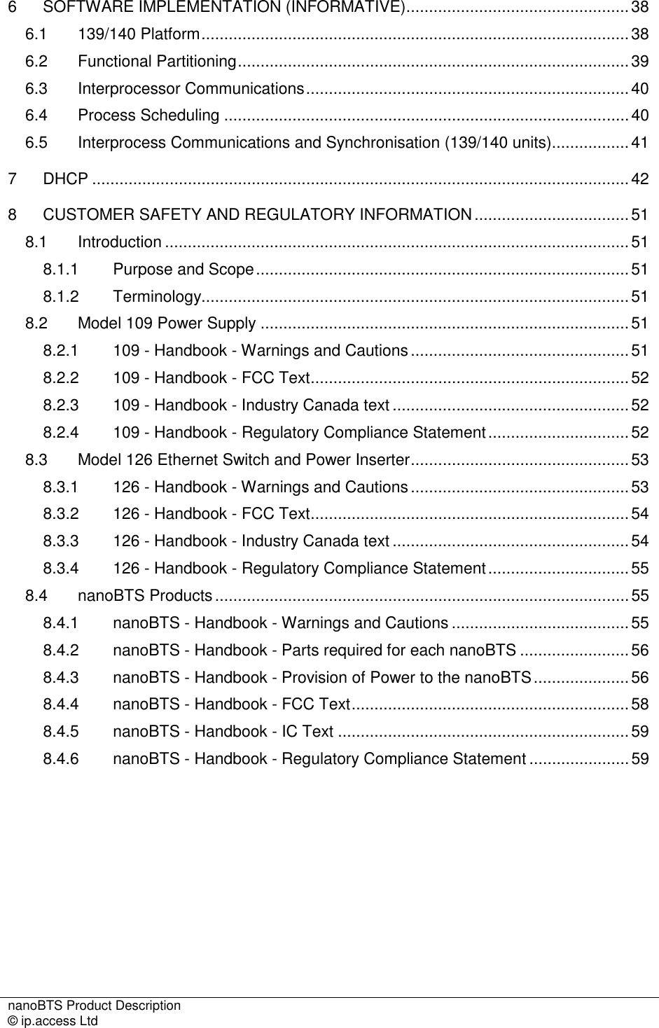
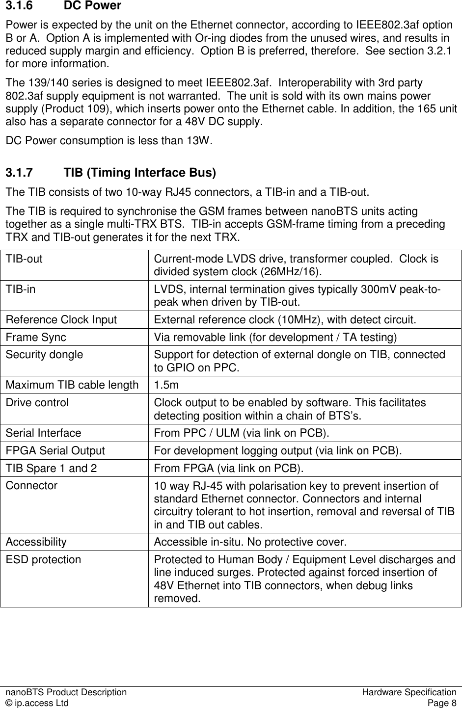
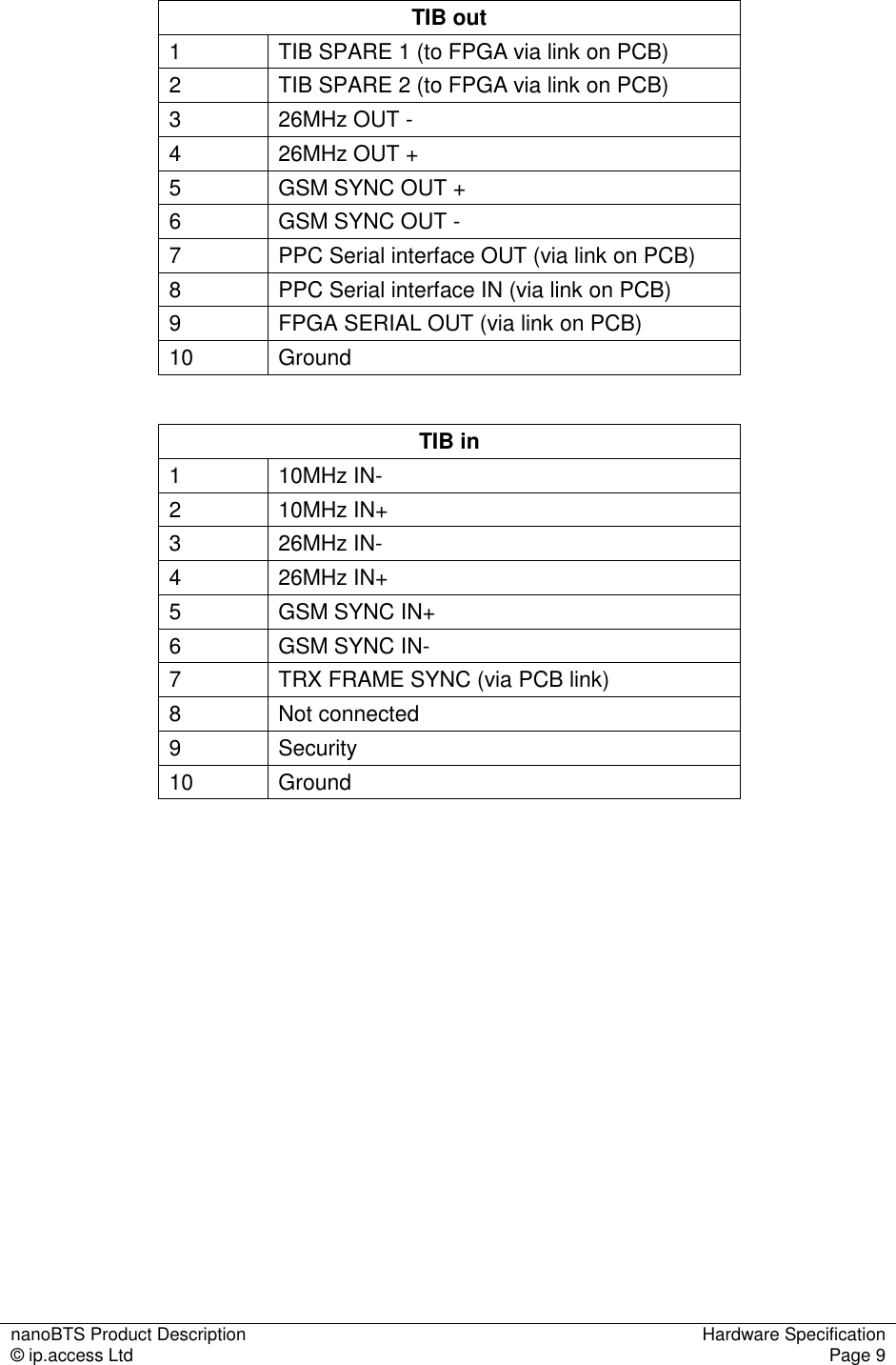
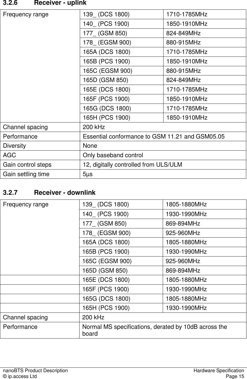
![nanoBTS Product Description Hardware Specification © ip.access Ltd Page 6 The 139/140 series nanoBTS is shown in Figure 3 and Figure 4. Figure 3 - 139/140 nanoBTS Status IndicatorRJ45(48Vdc)EthernetTIB In TIB Out (26MHz) Figure 4 - 139/140 nanoBTS connectors 3.1.2 Size, Shape and Weight The 165A/B series nanoBTS fits in an envelope approximately 276mm long, 208mm wide and 63mm deep. The plan shape is roughly rectangular. The 165C/D/G/H series nanoBTS fits in an envelope approximately 291mm long, 222mm wide and 63mm deep. The plan shape is roughly rectangular. These dimensions should not be used for space planning in installation. See [INST_300] for more information on space requirements of the 165 series. The unit weighs less than 2kg. When used in multi-TRX deployments, two 165 units may be mounted together in a "stacked" configuration (see [INST_300] for details). The 139/140 series nanoBTS fits in an envelope approximately 275mm long, 210mm wide and 75mm deep. The plan shape is roughly elliptical. These dimensions should not be used for space planning in installation. See [INST_300] for more information on space requirements of the 139 series. The unit weighs less than 3kg. Heavy finning on the back of the unit is provided for convective cooling when vertically mounted. When wall mounted, these fins are intended to be vertical.](https://usermanual.wiki/ip-access/KU02ZZS.Product-Description/User-Guide-1105686-Page-11.png)
![nanoBTS Product Description Hardware Specification © ip.access Ltd Page 7 Fins are also provided on the front of the unit, normally obscured by the plastic cosmetic cover. When ceiling mounted or in any other horizontal situation, the plastic cosmetic cover is intended to be removed to allow airflow across the front fins. 3.1.3 GSM Standards Standards Parts Date 3GPP 11.21 Essential Compliance v8.8.0 3GPP 05.05 EGSM, Power Class P1, as called up by 3GPP 11.21/Essential Compliance v8.14.0 ETS 301 489 Part 8 – specific requirements for GSM basestations v1.1.1 For a complete and normative statement of nanoGSM system approvals and standards compliance, see [NGSM_SOC]. 3.1.4 Environmental Operational: Temperature Humidity -5 ~+45C ambient 5-90% non-condensing Storage: Temperature Humidity -20 ~ +80C ambient 5-90% non-condensing Cold Start: Warm-up period from cold In-spec operation within 10 minutes Hot Start: System reset without loss of power supply In-spec operation within 3 minutes ETS 300-019-1-1 ETS 300-019-1-2 ETS 300-019-1-3 Storage Class 1.1 Transport Class 2.3 Operation Class 3.1 EN301-489-1 EN301-489-8 EN301-502 EMC general Standards: EN60950 / IEC 60950 /UL60950 Safety Note that the 139/140 and 165 series are not hermetically sealed. See [NGSM_APR] for complete approvals and standards compliance documentation. 3.1.5 Ethernet Interface The Ethernet connector is 8-way RJ-45 female (screened on the 165 C/D/G/H). The Ethernet physical layer is 10/100baseT, full-duplex, auto-negotiate.](https://usermanual.wiki/ip-access/KU02ZZS.Product-Description/User-Guide-1105686-Page-12.png)
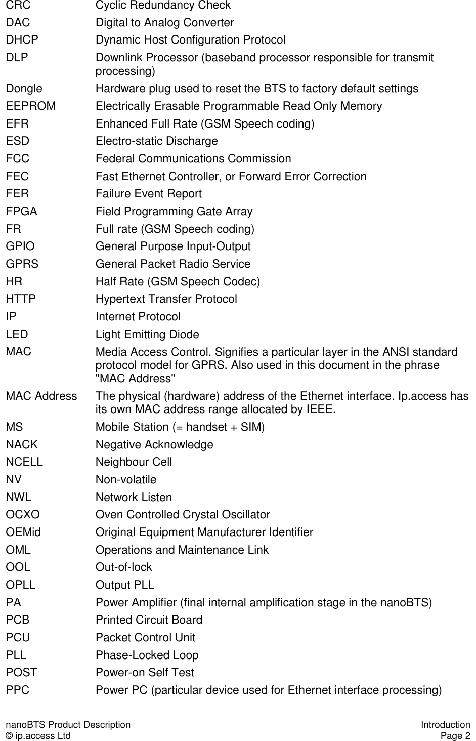
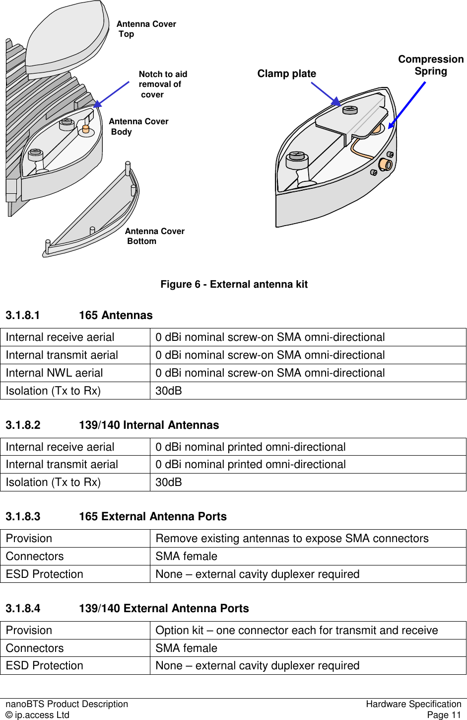
![nanoBTS Product Description Hardware Specification © ip.access Ltd Page 10 3.1.8 Antennas 165 nanoBTS units provide SMA connectors that are exposed when the antennas are unscrewed as illustrated in Figure 5. (The removable antennas for 165C, 165D, 165G and 165H are shown in Figure 5. The removable antennas for 165A and 165B are smaller. 165E and 165F have no removable antennas.) Figure 5 - Removable antennas – 165 hardware The 139/140 series is normally used with its own internal antennas, of which there is one for transmit and one for receive. The units can be supplied with an optional external antenna kit, which allows the unit to be connected to an external duplexer, booster system, distributed antenna system or other external radio system (not supplied by ip.access). See [INST_300] for more details on the external antenna kit. Figure 6 shows the 139/140 unit with external antenna kit fitted. The external antenna kit introduces negligible loss, so the transmitter and receiver specifications given in sections 3.2.5, 3.2.6 and 3.2.7 apply equally at the external antenna ports.](https://usermanual.wiki/ip-access/KU02ZZS.Product-Description/User-Guide-1105686-Page-15.png)
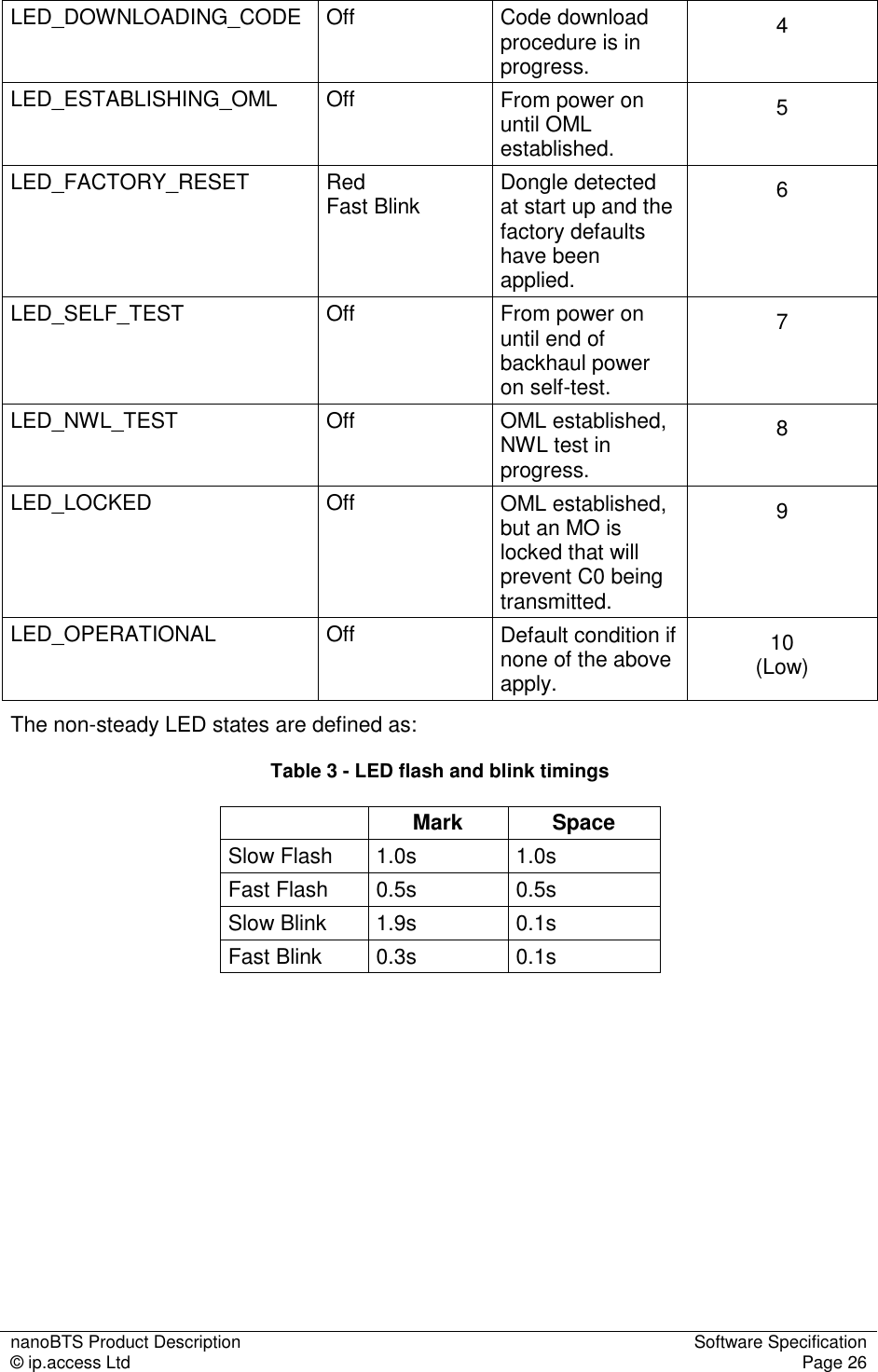
![nanoBTS Product Description Software Specification © ip.access Ltd Page 18 5.2 Explicitly Not Supported • Multi-Slot Circuit Switched Data • EDGE on 139 series BTS (supported by 165 with SR3 software) • Half-rate speech codec (HR) • Advanced Multi-Rate speech codec (AMR) on 139/140 series BTS (supported by 165 with SR3 software) • IP Security • IP Version 6 • HTTP server • VGCS and VBS • SOLSA 5.3 Standards The base software support level is 3GPP Release 99 unless otherwise stated. 5.4 Reset Behaviour 5.4.1 Boot On Power on, the bootstrap code changes the LED to state LED_SELF_TEST (note that this may actually mean that the LED is turned ‘off’ if the LED is disabled in EEPROM config – see section 5.8.2. The bootstrap code performs Power-On-Self-Test (POST) on "cold" boot (if "Disable POST" flag is cleared in EEPROM). Warm boots do not perform POST. The POST procedures check • RAM on all processors • Code Memory on all processors – checksum verification of code banks • EEPROM Memory – checksum verification of attribute blocks 5.4.2 Software Code Banks and Software Bank Activation nanoBTS software is stored in two banks, and the active bank is indicated by a EEPROM switch. If the active bank POST fails, then the inactive bank will be booted – with an associated Failure Event Report. If the inactive bank POST also fails, then the LED indicates LED_SELF_TEST_FAILURE. nanoTRX software is downloaded to the inactive bank using the software download tool BtsInstaller (see [INST_300]). Software download proceeds without interrupting the operation of the BTS. The active bank flag is then altered. The next time the BTS restarts, the new software will be run.](https://usermanual.wiki/ip-access/KU02ZZS.Product-Description/User-Guide-1105686-Page-23.png)
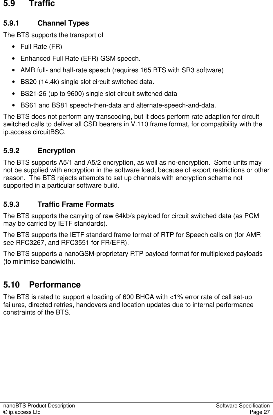
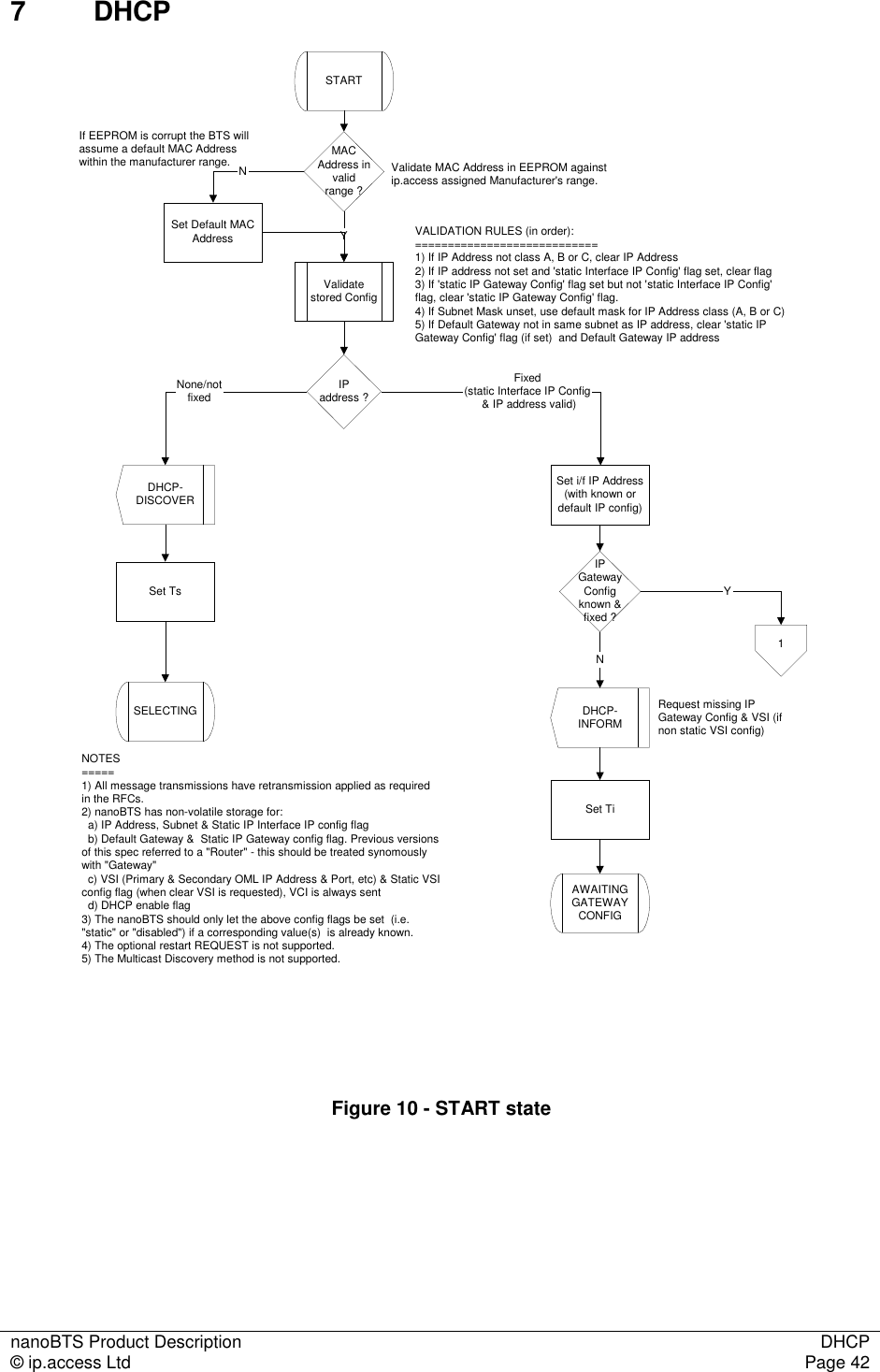
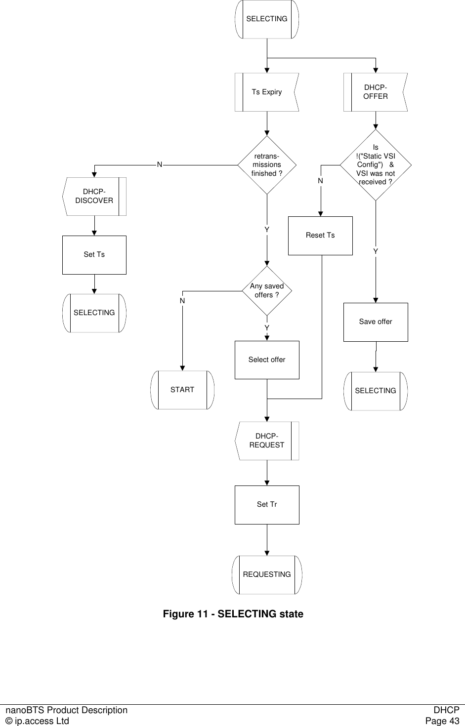
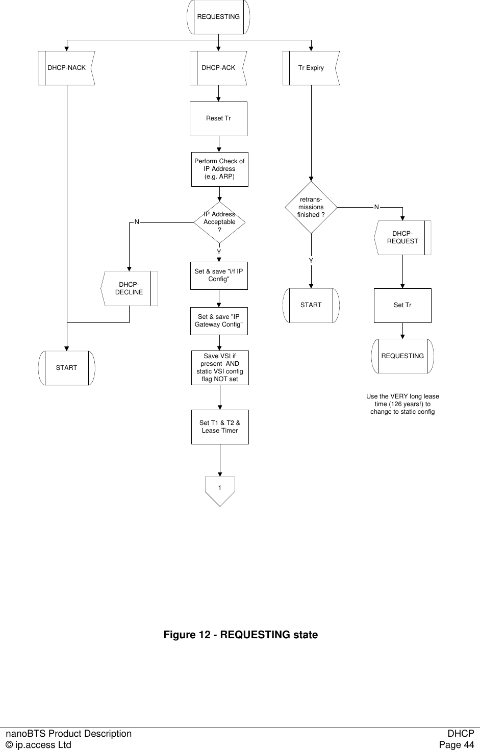
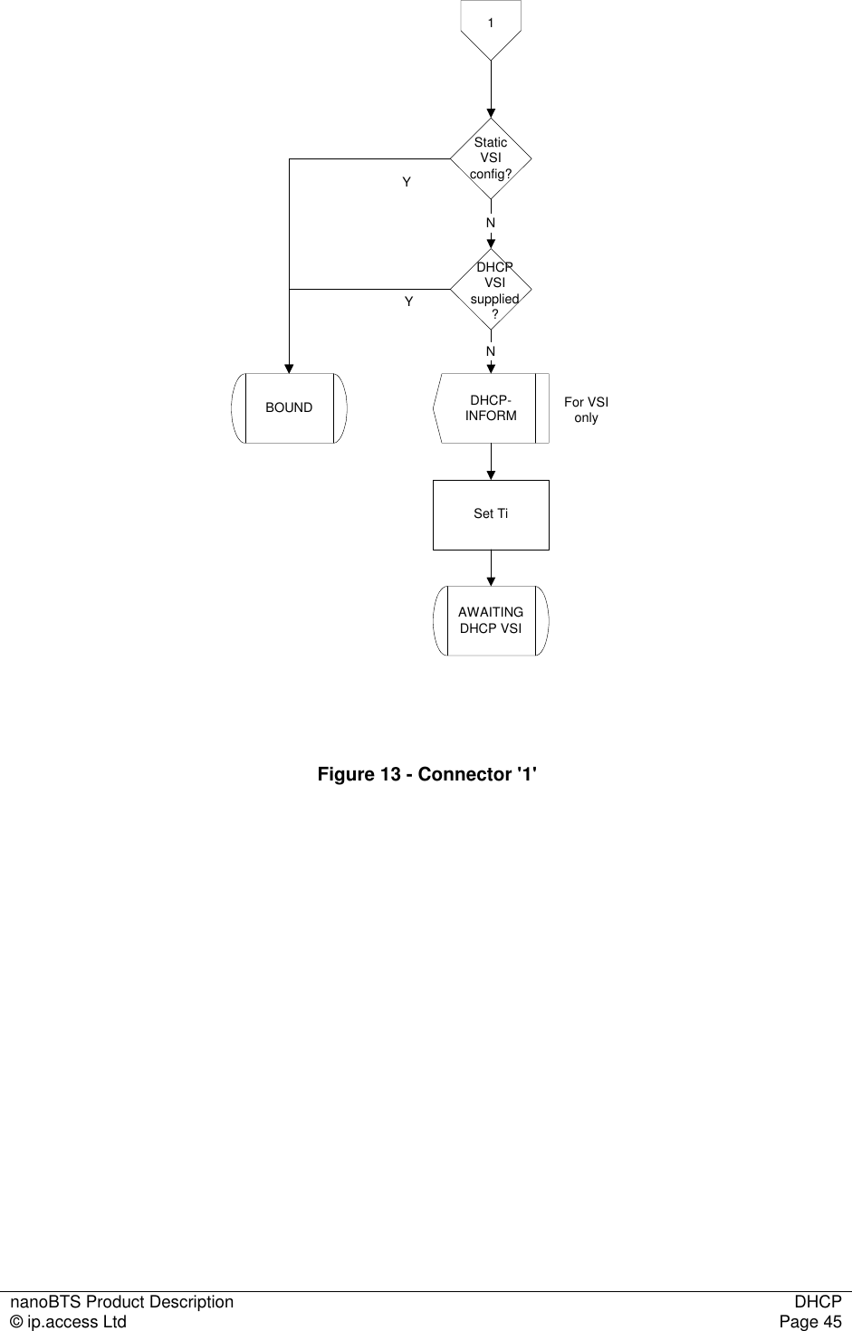
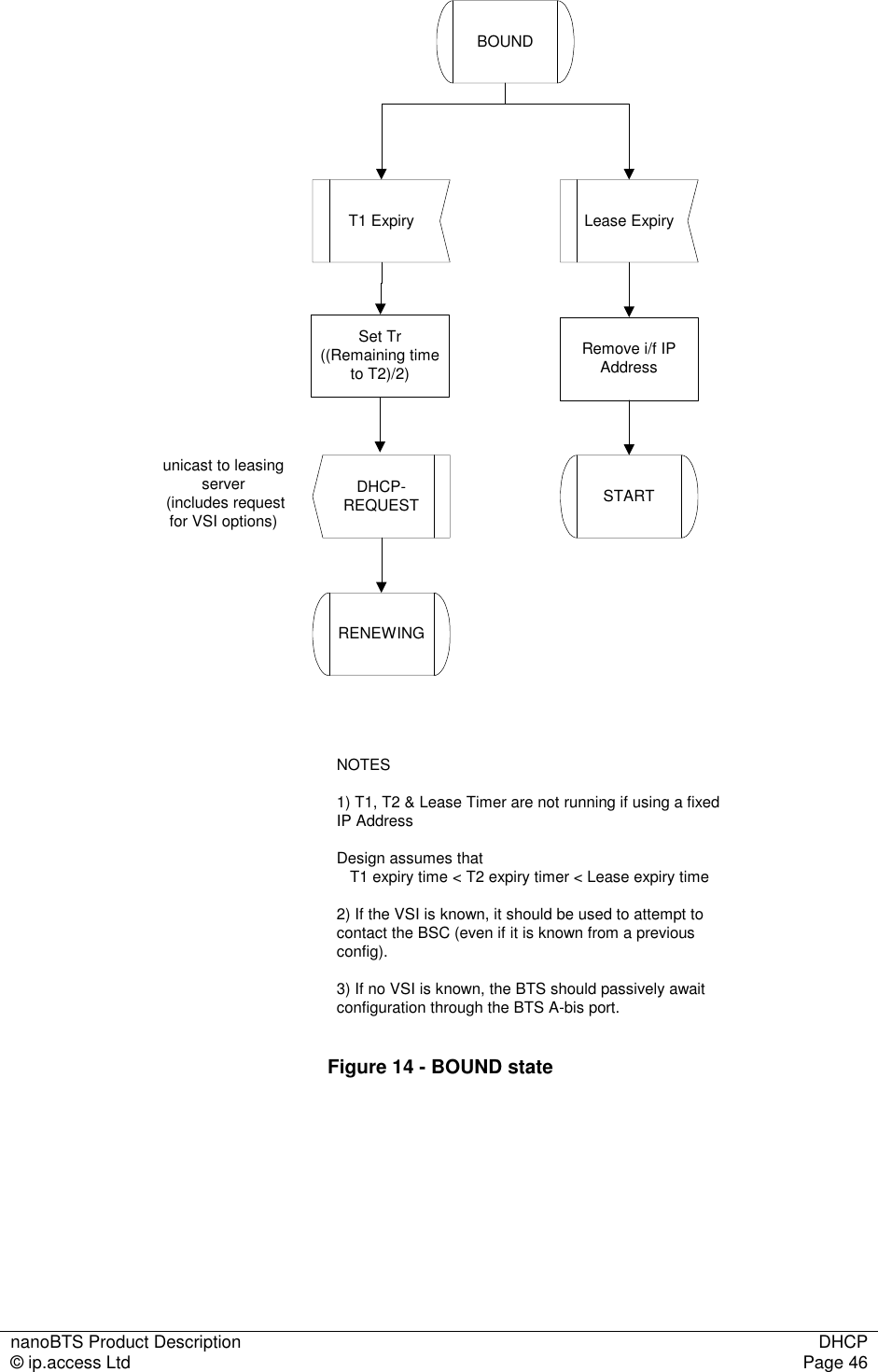
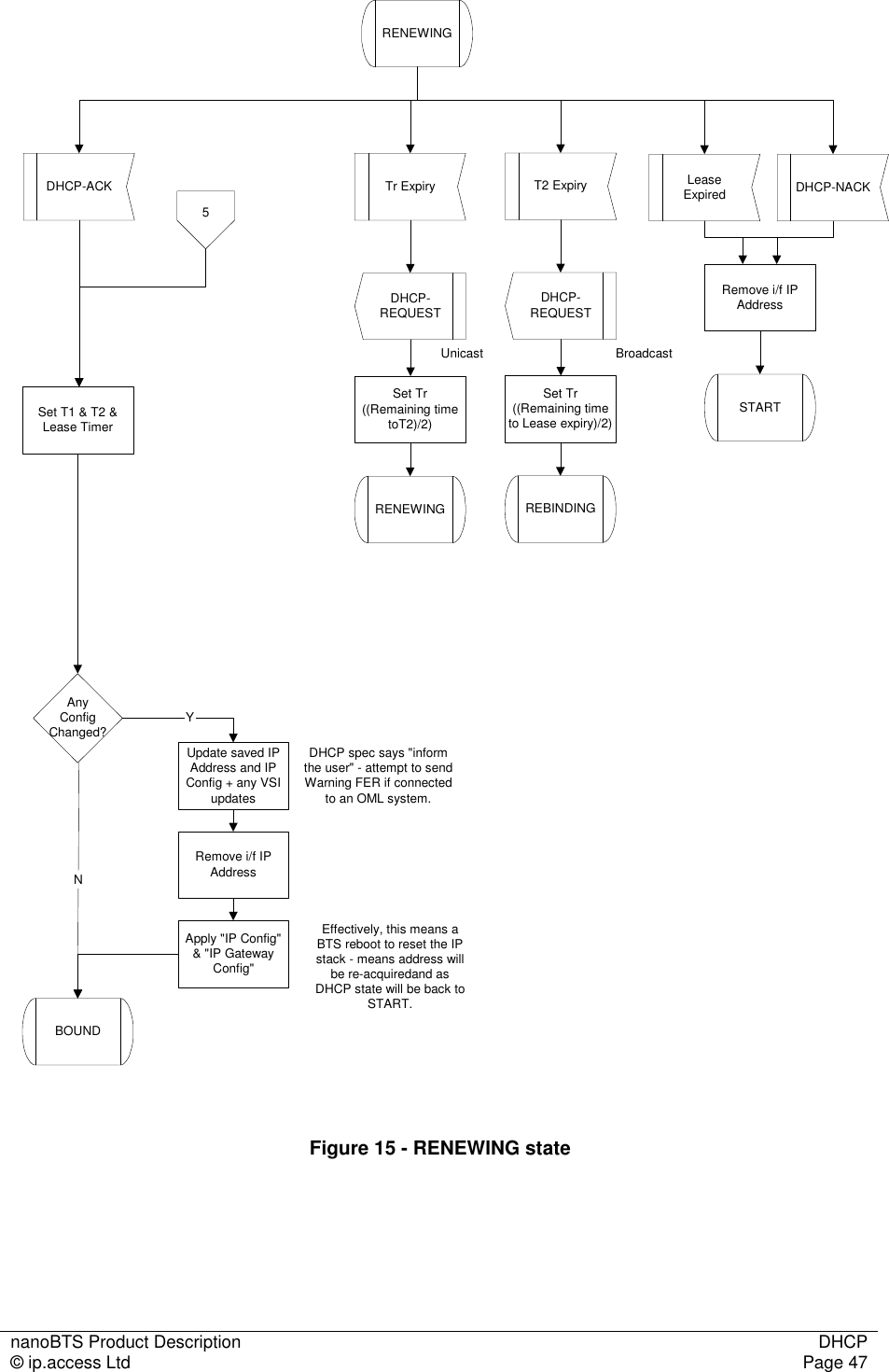
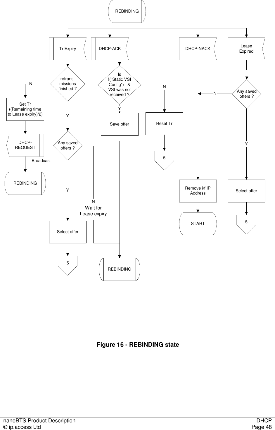
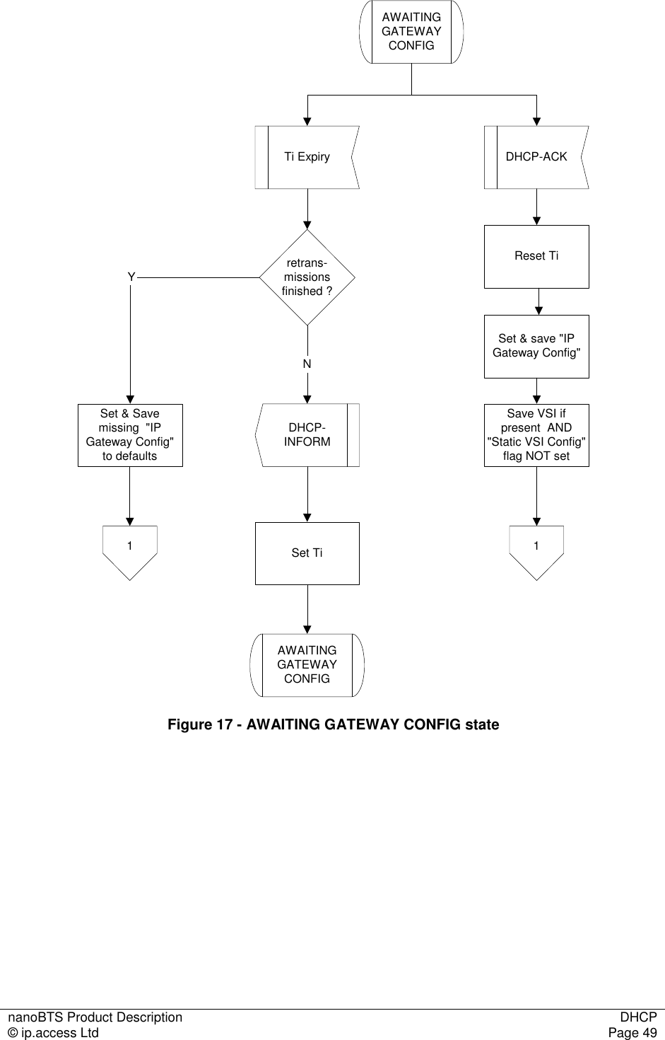
![nanoBTS Product Description Software Specification © ip.access Ltd Page 19 5.4.3 Reset Reason If the BTS undergoes a fatal software reset of any sort, a byte indicating the "reset reason" is stored in memory before the reset is initiated. During the reset procedure, this "reset reason" byte is read out, and sent to the management system as a Failure Event Report. 5.5 Configuration 5.5.1 DHCP The BTS supports the ip.access specific implementation of DHCP. 5.5.2 Fallback OML Link The BTS supports a fallback link to its BSC, by configuring the "Primary OML Fallback Address" and "Port" and the associated "Fallback Timeout". If the fallback address and port are configured, then the BTS will behave as follows • On startup, the primary, non-fallback address is repeatedly tried, until either connection succeeds or the fallback timer expires • If the fallback timer expires, then the fallback address is repeatedly tried, until either connection succeeds or the fallback timer expires • If the fallback timer expires, then the non-fallback address is tried again, and so on If the fallback timer is zero (its default value) then the non-fallback and fallback addresses are tried alternately. If the fallback address and port are unconfigured, then the non-fallback address is tried repeatedly for ever. 5.5.3 Management Model and Attributes The management model is fully defined in [REF_110]. An example class tree for the 1800MHz EDGE/AMR BTS is given below.](https://usermanual.wiki/ip-access/KU02ZZS.Product-Description/User-Guide-1105686-Page-24.png)
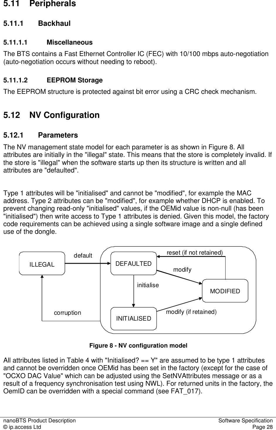
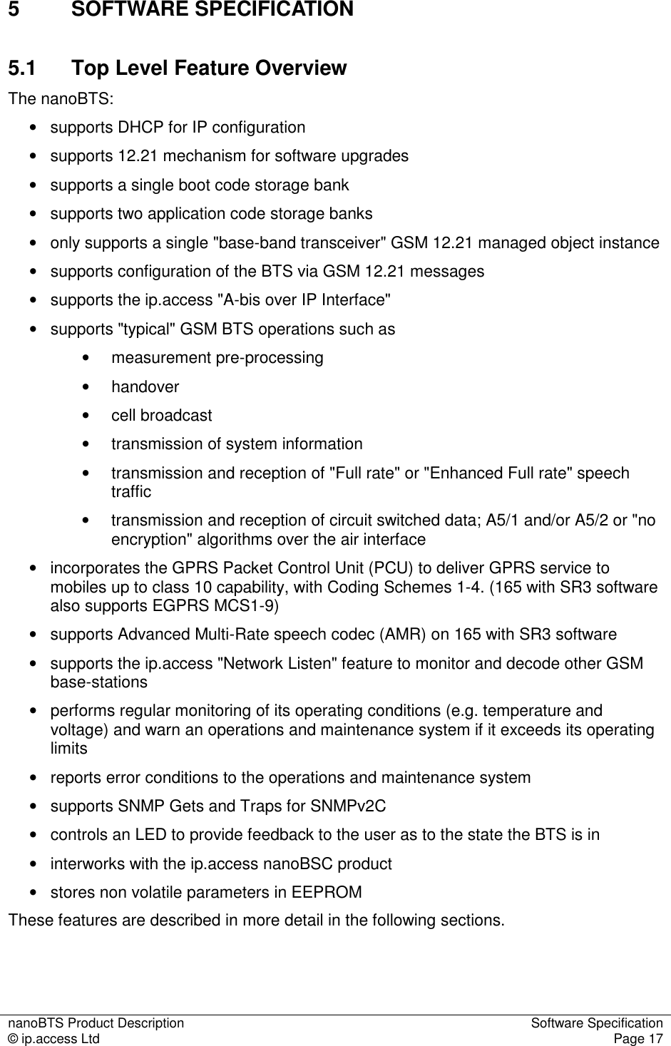
![nanoBTS Product Description Software Specification © ip.access Ltd Page 20 btsNsvc_001btsEdge1800_005btsSiteManager_0041..11..1bss_0010..2000..200channelAmr_002basebandTransceiver_0041..41..48..88..8gprsCellEgprs_004btsNse_0020..10..11..21..21..11..1 Figure 7 - 1800MHz, EDGE/AMR nanoBTS management model 5.5.4 Code Download The BTS supports code download by using the software download function of the BtsInstaller tool (see [INST_300]). The BTS examines the header of the downloaded file to determine if the BTS hardware is compatible with the SW. If any part of the code download is incompatible with the hardware, then the code download is NACK’d and the transfer is aborted, without affecting the running or the stored code. For DHCP triggered TFTP, once the code has been successfully downloaded and the TFTP is complete, then the BTS shall set an internal flag (not set / get able from the outside world) to "disable DHCP triggered TFTP on reboot" in EEPROM. The BTS shall change the "Default" index to the index that it has just successfully downloaded. Then the BTS should reset itself. Once reset the BTS shall clear this flag (so that on the next reboot a DHCP triggered TFTP download is permitted) and begin executing this code. If a code download fails or is aborted for any reason, then a Failure Event Report is sent to the management system.](https://usermanual.wiki/ip-access/KU02ZZS.Product-Description/User-Guide-1105686-Page-25.png)
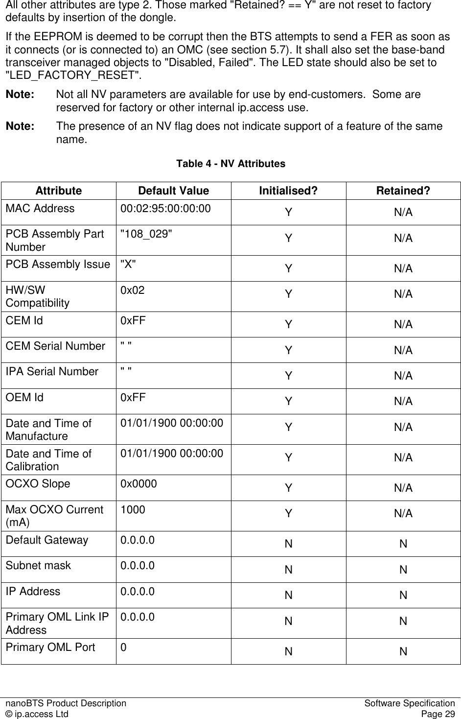
![nanoBTS Product Description Software Specification © ip.access Ltd Page 21 5.6 Air Interface 5.6.1 Channel Combinations The valid channel combinations on a "standalone" nanoBTS or on the Site Master TRX of a Multi-TRX configuration are: Timeslot Channel Types Allowed Restrictions TS0 Full BCCH Combined BCCH Combined BCCH with CBCH TS1 SDCCH/8 SDCCH/8 with CBCH Only if TS0 is Full BCCH TCH/F, TCH/H Requires 165 BTS with SR3 software Dynamic TCH/F, TCH/H Requires 165 BTS with SR3 software Dynamic PDCH/TCH PDCH TS2-7 TCH/F, TCH/H TCH/H requires 165 BTS with SR3 software Dynamic PDCH/TCH PDCH The valid channel combinations on a Slave TRX of a Multi-TRX configuration are: Timeslot Channel Types Allowed Restrictions TS0 and TS2-7 TCH/F, TCH/H Dynamic TCH/F, TCH/H TCH/H and Dynamic TCH/H requires 165 BTS with SR3 software TS1 SDCCH/8 Must be without CBCH TCH/F, TCH/H TCH/H requires 165 BTS with SR3 software Dynamic TCH/F, TCH/H Requires 165 BTS with SR3 software The BTS supports different Training Sequence Codes (TSC) on each channel. 5.6.2 Power Control and Handover The BTS supports MS Power Control algorithm according to [GSM05.08] annex A. The BTS supports "Non Synchronised" handover. The BTS does not support "Synchronised" handover of any variant. The BTS performs Measurement Pre-processing to determine when a handover should occur and provides an ordered candidate list of Neighbour Cells to handover to (according to GSM 05.08 Annex A). The algorithm may be configured via "Measurement Pre-Process defaults" message (see section 5.14.2) in which case it is enabled. Configuration is BSC specific. Handovers can occur between different bands (e.g. 900MHz and 1800MHz). The BTS sends RfResourceInds to monitor the background RF received power on unused timeslots.](https://usermanual.wiki/ip-access/KU02ZZS.Product-Description/User-Guide-1105686-Page-26.png)